EP0652099A2 - Procédé pour la fabrication de pare-soleil pour véhicules et pare-soleil réalisé selon ledit procédé - Google Patents
Procédé pour la fabrication de pare-soleil pour véhicules et pare-soleil réalisé selon ledit procédé Download PDFInfo
- Publication number
- EP0652099A2 EP0652099A2 EP94116215A EP94116215A EP0652099A2 EP 0652099 A2 EP0652099 A2 EP 0652099A2 EP 94116215 A EP94116215 A EP 94116215A EP 94116215 A EP94116215 A EP 94116215A EP 0652099 A2 EP0652099 A2 EP 0652099A2
- Authority
- EP
- European Patent Office
- Prior art keywords
- recess
- specified
- shells
- sun visor
- shell
- Prior art date
- Legal status (The legal status is an assumption and is not a legal conclusion. Google has not performed a legal analysis and makes no representation as to the accuracy of the status listed.)
- Withdrawn
Links
Images


Classifications
-
- B—PERFORMING OPERATIONS; TRANSPORTING
- B29—WORKING OF PLASTICS; WORKING OF SUBSTANCES IN A PLASTIC STATE IN GENERAL
- B29C—SHAPING OR JOINING OF PLASTICS; SHAPING OF MATERIAL IN A PLASTIC STATE, NOT OTHERWISE PROVIDED FOR; AFTER-TREATMENT OF THE SHAPED PRODUCTS, e.g. REPAIRING
- B29C51/00—Shaping by thermoforming, i.e. shaping sheets or sheet like preforms after heating, e.g. shaping sheets in matched moulds or by deep-drawing; Apparatus therefor
- B29C51/26—Component parts, details or accessories; Auxiliary operations
- B29C51/266—Auxiliary operations after the thermoforming operation
- B29C51/267—Two sheets being thermoformed in separate mould parts and joined together while still in the mould
-
- B—PERFORMING OPERATIONS; TRANSPORTING
- B29—WORKING OF PLASTICS; WORKING OF SUBSTANCES IN A PLASTIC STATE IN GENERAL
- B29C—SHAPING OR JOINING OF PLASTICS; SHAPING OF MATERIAL IN A PLASTIC STATE, NOT OTHERWISE PROVIDED FOR; AFTER-TREATMENT OF THE SHAPED PRODUCTS, e.g. REPAIRING
- B29C49/00—Blow-moulding, i.e. blowing a preform or parison to a desired shape within a mould; Apparatus therefor
- B29C49/02—Combined blow-moulding and manufacture of the preform or the parison
- B29C49/06905—Using combined techniques for making the preform
- B29C49/0691—Using combined techniques for making the preform using sheet like material, e.g. sheet blow-moulding from joined sheets
-
- B—PERFORMING OPERATIONS; TRANSPORTING
- B60—VEHICLES IN GENERAL
- B60J—WINDOWS, WINDSCREENS, NON-FIXED ROOFS, DOORS, OR SIMILAR DEVICES FOR VEHICLES; REMOVABLE EXTERNAL PROTECTIVE COVERINGS SPECIALLY ADAPTED FOR VEHICLES
- B60J3/00—Antiglare equipment associated with windows or windscreens; Sun visors for vehicles
- B60J3/02—Antiglare equipment associated with windows or windscreens; Sun visors for vehicles adjustable in position
- B60J3/0204—Sun visors
- B60J3/0278—Sun visors structure of the body
-
- B—PERFORMING OPERATIONS; TRANSPORTING
- B29—WORKING OF PLASTICS; WORKING OF SUBSTANCES IN A PLASTIC STATE IN GENERAL
- B29C—SHAPING OR JOINING OF PLASTICS; SHAPING OF MATERIAL IN A PLASTIC STATE, NOT OTHERWISE PROVIDED FOR; AFTER-TREATMENT OF THE SHAPED PRODUCTS, e.g. REPAIRING
- B29C2791/00—Shaping characteristics in general
- B29C2791/004—Shaping under special conditions
- B29C2791/007—Using fluid under pressure
-
- B—PERFORMING OPERATIONS; TRANSPORTING
- B29—WORKING OF PLASTICS; WORKING OF SUBSTANCES IN A PLASTIC STATE IN GENERAL
- B29L—INDEXING SCHEME ASSOCIATED WITH SUBCLASS B29C, RELATING TO PARTICULAR ARTICLES
- B29L2031/00—Other particular articles
- B29L2031/30—Vehicles, e.g. ships or aircraft, or body parts thereof
- B29L2031/3005—Body finishings
- B29L2031/3035—Sun visors
Definitions
- the present invention relates to a method for producing sun visors for vehicles, and to a sun visor with this method.
- the known sun visors which are produced in the manner described above, suffer mainly from the deficiency that they have, in particular, quite high weights, which are due both to the presence of the reinforcement and to the large amount of material that the reinforcement itself surrounds.
- sun visors made in the manner described above have relatively low stiffness in most applications, both in terms of bending forces and in terms of torsional movements, despite the presence of the internal reinforcements ; in general, such sun visors are also characterized by fairly high manufacturing costs, due both to the high amount of material to be used and to the fact that after these materials have been molded and bonded together, they are no longer readily recycled and re-used can be.
- the aim of the present invention is to provide a method for producing sun visors which makes it possible to avoid the disadvantages set out above.
- a method of manufacturing sun visors for vehicles which method comprises individual phases for manufacturing the main body of a sun visor and is characterized in that the manufacture of this main body of the sun visor is obtained by a single operation, namely by pressure blow molding is and includes phases, according to which two half-shells are simultaneously formed and these half-shells themselves are connected to each other along the corresponding outer edges by simple pressure.
- the shaping and the mutual connection of the two half-shells mentioned are carried out in accordance with the method specified above, in that two plates of a plastic material are inserted between two mold halves of a compression mold used for shaping, a corresponding sheet of a coating material being inserted between each plate and the corresponding mold half and the two mold halves are then closed and at the same time a stream of a pressurized fluid is blown between the plates mentioned, so that at the same time the deformation of the plates and their connection to one another is achieved and at the same time the application of each of them for coating by simple compression serving sheets on the corresponding plate is reached.
- the present invention relates to a sun visor for vehicles.
- a sun visor for vehicles which comprises a main body, characterized in that this main body of the sun visor is a hollow body which comprises a first and a second half-shell, which are obtained by pressure blow molding and at least along with each other the respective outer edges are firmly connected.
- each of the half shells specified comprises a molded section of plastic material and a sheet of coating material which is applied to the molded section and fixedly attached to the molded section itself.
- the number 1 denotes a sun visor for vehicles in general as well as specifically for passenger cars.
- the screen 1 comprises the hollow body 1a of a sun visor, which in turn comprises two half-shells, marked by 2 and 3, of essentially rectangular shape, which are firmly connected to one another along the respective outer edges 3a (FIG. 2).
- each of these half-shells 2 and 3 has an essentially C-shaped shape in cross section.
- Each half-shell 2 and 3 has a front wall 4 and a side wall 5, which extends at right angles with respect to the corresponding wall 4, starting from an edge of the corresponding wall 4 itself, being fixed to the wall 5 of the other section 2, 3 connected is.
- Each half-shell 2, 3 is fixed by an internal molded section 6, which is obtained from a thermally deformable plastic material, preferably from filled polypropylene or - alternatively - from ABS, or from any regenerated plastic material, as well as from a sheet 7 of one Coating material, preferably made of synthetic leather or textile.
- the sheets 7 are applied to an outer surface of the corresponding section 6; According to the illustrations in FIG. 2, these sheets each have edges 9 which are arranged on the top of one another.
- the half-shells 2 and 3 define in their interior a recess 11 which, in a position which is in the vicinity of the walls 5, receives a device 14 (FIG. 1) which is known in principle and which is used to fasten the main part of the sun visor 1a is intended with a hollow and serving arm 15, one end portion of this arm forming part of the device 14, and an opposite end portion (not shown here) of this arm being adapted to refer to a known - and not shown - Way to be connected to a body (not shown) of a vehicle (not shown).
- the half-shell 3 has an external recess 16, which is obtained by plastic deformation of a central section of the corresponding wall 4 and is delimited by its own rear wall 17, which is essentially runs parallel to the walls 4.
- the recess 16 has an opening 18, closed off by a transparent plate 19, which in the specific example described here consists of a transparent material and which is connected to the half-shell 3 in order to jointly to limit a pocket 20 with the recess 16, which is located as a holder for objects on the sun visor 1.
- the plate 19 has a rectangular shape and occupies a position according to which the long sides of the plate extend in a position which is parallel to the long sides of the half-shells 2 and 3; in addition, the plate 19 has its own outer surface, which lies essentially in the same plane as the outer surface of the corresponding wall 4.
- the plate 19 is made of a plastic material, preferably by stamping, or - alternatively - by injection molding.
- the plate 19 is limited by corresponding flat and smooth surfaces, or - alternatively - by satin flat surfaces; it has a pair of slots 22 which, in the example described, extend parallel to one another and parallel to the longitudinal sides of the plate 19 already mentioned.
- the plate 19 is connected to the half-shell 3 by a series of snap buttons 23, which are known in principle, and which are distributed along at least two edges of the plate 19 itself. According to a variant, not shown, the two edges of the plate 19 mentioned are connected to the half-shell 3 by means of electric welding.
- the half-shell 3 is provided with a further recess 24, which is obtained in the example specifically described in a position which comes to lie next to the recess 16, and at least partially accommodates a milk microphone 24a, the ( Cabling (not shown) runs within the recess 11 and emerges from this recess 11 itself, preferably via an opening (not shown) or, alternatively, via the arm 15 already mentioned and used for holding.
- the sun visor 1 does not have the element 19 which serves to close the recess 16, and within this recess 16 there is an electronic route indicator 25 which is suitable for indicating to a user all the information which is necessary are, for example, to be able to move within a city.
- the electronic indicator 25 has its own wiring 25a, which also extends within the recess, and which exits from this recess 11 itself through the arm 15, in order then to be connected to an external (not shown) receiving antenna which the vehicle (not shown) is attached, to receive different signals from a corresponding transmitter (not shown).
- the cabling 25a mentioned emerges from the recess 11 through a secondary mounting element 25b (FIG. 3), which is located at the end of the main body 1a of the sun visor, which is opposite the arm 15, and which is suitable for snapping a seat to be carried by a body (not shown) attached to the body of the vehicle (not shown).
- a secondary mounting element 25b FIG. 3
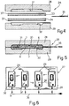
- thermoregulation - form 26 which is kept at a temperature of approximately 80 degrees Celsius and forms part of a shaping group 27 ( Figure 6), which comprises several forms 26 which are arranged side by side; this group is suitable to allow the production of several sun visors at the same time.
- mold 26 comprises first and second mold halves, respectively designated 28 and 29, which can move relative to one another, under the thrust of a known and not shown active group; in their interior they form a chamber 30 (FIG. 5), delimited by two shaped surfaces 31 and 32, the surface 31 being obtained from the mold half 28 and to be regarded as complementary to the outer surface of the half-shell 2, whereas the surface 32 is formed from the Mold half 29 is obtained and is complementary to the outer surface of the half-shell 3 itself.
- the manufacture of the sun visor 1 is carried out by inserting a first and a second plate between the mold halves 28 and 29, which are designated here by the reference numerals 33 and 34 and are kept apart from one another, by injecting one pressurized fluid that is dispensed from a corresponding nozzle 35, which is connected in a known manner to a known compressed air circuit 36, which is shown schematically in Figure 6.
- the plates 33 and 34 are both made of plastic material and, before being placed in the corresponding mold 26, they are heated to a temperature which is preferably variable between 140 and 180 degrees Celsius.
- an associated flexible sheet 34 is inserted between each of the plates 33 and 34 and the corresponding mold halves 28 and 29, which defines the corresponding sheet 7 of the associated section 6, which is used for coating, after the shaping has been completed, which sheet is likewise fixed by a corresponding plate 33, 34 after the shaping has been completed.
- the mold halves 28 and 29 are closed; at the same time, a fluid with higher pressure is introduced via the nozzle 35 between the plates 33 and 34; due to the pressure that the mold halves 28 and 29 exert on one side and on the other side the fluid, the blades 37 are pressed against the corresponding plate 33, 34 and firmly connected to the associated plate itself, which - also during the Supply of the pressurized fluid - gradually deformed until the corresponding sheet comes into contact with the surface of the corresponding mold half. Also during the closing of the mold halves 28 and 29, the respective outer sections of the plates 33 and 34 are pressed against one another by the mold halves 28 and 29 and glued to one another by simple pressure.
- the mold halves 28 and 29 are now held in their closed position for a certain period of time, which is normally approximately 60 to 90 seconds; then they are opened and the molded hollow body is trimmed to obtain the main part of the sun visor 1a.
- a first series of the push buttons 23 already mentioned is subsequently connected to the half-shell 3, while a further series of these buttons 23 is connected to the plate 19; subsequently the plate 19 is let into the recess 16 and connected to the half-shell 3.
- the connection of the already mentioned first row of buttons with the half-shell 2 is carried out simultaneously with the shaping of the hollow body 1a.
- FIG. 7 relates to a sun visor 38, which is similar to the visor 1, and whose components - as far as possible - are identified by the same reference numbers that are used for the corresponding parts of the visor 1 itself.
- the main body of the sun visor 1a is obtained by the same method with which the main body 1a of the aperture 1 has already been obtained; it differs from the main body 1a of the panel 1 itself in that this body has an external recess 39 which is obtained within the wall 4 of the half-shell 2 itself at the level of the recess 16; they are obtained by plastic deformation of a middle one Section of the wall 4 itself; it is limited by its own rear wall 40, which runs parallel to the wall 4 itself.
- the recess 39 has its own opening 41, which is closed off by a plate 42 made of a plastic material, this being suitable for delimiting together with the recess 39 itself a further pocket or a space 43 which is used to receive Serves documents and is located at the aperture 38 itself.
- the plate 42 is rectangular in shape and is connected by a hinge to a portion of the half-shell 2 which is adjacent to the opening 41, via a virtual hinge 44 which is suitable for connecting it to the plate 42 enable itself to rotate between an open position ( Figure 7), in which it allows access to the recess 39, and a closed position ( Figure 8), in which it closes the opening 41 and forms the pocket 43.
- Figure 7 open position
- Figure 8 Figure 8
- the hinge 44 is obtained by welding a longitudinal side of the plate 42 to the half-shell 2, preferably by electric welding, and by the plate 42 in its own closed position by means of a tear-off which serves to hold it back. Element 45 is held, which is on the opposite side of the plate 42 - with respect to the hinge 44 -.
- the plate 42 presents a transverse weakening line, which is suitable for forming the hinge 44 mentioned, as well as an edge area, which is firmly connected to the half-shell 2, preferably via a plurality of pushbuttons serving for connection and latching.
- the plate 42 carries a mirror surface 46 which is connected to the inner surface of the plate 42 itself and which has a thickness due to which it only occupies part of the recess 39 when the plate 42 is in its own closed position.
- the panels 1 and 38 described are characterized by the fact that they have a hollow sun visor body 1 a, which are characterized above all by very low weights, and that at the same time they - although they have no internal reinforcement to reinforce them - have a fairly high strength - both with respect to flexion and torsion movements.
- the special type of design of the half-shells 2 and 3 not only makes it possible to obtain panels which are free from any shape and finishing defects and which are therefore to be regarded as particularly positive from an aesthetic point of view; in addition, any material that is in sheet form can be used as the coating material, and in particular a coating material that has the same tints and colors as the materials for coating the sky of the vehicle (not shown), for example.
- the panels 1 and 38 described are distinguished by very low manufacturing costs, not only because of the simplicity of manufacture, but also because of the fact that different types of plastic materials can be used for their manufacture, in particular also recyclable or recycled plastic materials.
- the panels 1 and 38 described that do not depart from the scope of the present invention.
- different types of materials can be used both for the production of the sections 6 and also with regard to the production of the coating layer which is defined by the sheets 7.
- the half-shells 2 and 3 can have shapes which differ from the shapes described and illustrated, and they can be provided with further recesses which are the same as the recesses already described or differ from them and which, for example, are suitable for this purpose can to record an outside mirror or microphones that differ from the microphone 24a, or for example to record speakers of a sound system.
- the plate 19 can have a geometric design that differs from the design described here, and it can be connected to the half-shell 3 by using devices and modalities that differ from the types described .
- the half-shell 2 can be replaced by a half-shell which corresponds to the half-shell 2 of the panel 38, which in turn could not have both the recess 43 and the associated closing element 42.
- connection of the plates 33 and 34 to one another, as well as the connection of the plates 33 and 34 to the coating sheets 37, can take place in that the plate material becomes soft and sticky due to the heating.
- the coating sheets 37 are provided with an adhesion promoter coating (not shown) which ensures a connection with the plates 33 and 34.
Landscapes
- Engineering & Computer Science (AREA)
- Mechanical Engineering (AREA)
- Manufacturing & Machinery (AREA)
- Blow-Moulding Or Thermoforming Of Plastics Or The Like (AREA)
- Vehicle Step Arrangements And Article Storage (AREA)
Applications Claiming Priority (2)
| Application Number | Priority Date | Filing Date | Title |
|---|---|---|---|
| ITTO930825A IT1261329B (it) | 1993-11-04 | 1993-11-04 | Metodo per la realizzazione di alette parasole per veicoli e aletta parasole realizzata secondo tale metodo |
| ITTO000825 | 1993-11-04 |
Publications (2)
| Publication Number | Publication Date |
|---|---|
| EP0652099A2 true EP0652099A2 (fr) | 1995-05-10 |
| EP0652099A3 EP0652099A3 (fr) | 1996-06-05 |
Family
ID=11411848
Family Applications (1)
| Application Number | Title | Priority Date | Filing Date |
|---|---|---|---|
| EP94116215A Withdrawn EP0652099A3 (fr) | 1993-11-04 | 1994-10-14 | Procédé pour la fabrication de pare-soleil pour véhicules et pare-soleil réalisé selon ledit procédé. |
Country Status (3)
| Country | Link |
|---|---|
| EP (1) | EP0652099A3 (fr) |
| JP (1) | JPH07256736A (fr) |
| IT (1) | IT1261329B (fr) |
Cited By (9)
| Publication number | Priority date | Publication date | Assignee | Title |
|---|---|---|---|---|
| EP0714750A1 (fr) * | 1994-11-29 | 1996-06-05 | Franco Cesano | Installation pour la fabrication d'objets comprenant des noyaux et matière thermoplastique |
| EP0715980A1 (fr) * | 1994-12-07 | 1996-06-12 | Gebr. Happich GmbH | Procédé pour la fabrication d'un corps de pare-soleil d'un pare-soleil d'un véhicule encapsulé de matériau décoratif |
| EP0826534A3 (fr) * | 1996-09-03 | 2000-08-16 | Johnson Controls Interiors GmbH & Co. KG | Pare-soleil pour véhicules |
| FR2800330A1 (fr) * | 1999-10-27 | 2001-05-04 | Johnson Contr Interiors Gmbh | Pare-soleil pour vehicules |
| WO2003095252A1 (fr) | 2002-05-08 | 2003-11-20 | Fico I.T.M S.A. | Pare-soleil revetu |
| WO2003104002A3 (fr) * | 2002-06-07 | 2005-07-07 | Antolin Grupo Ing Sa | Pare-soleil |
| EP1571025A1 (fr) * | 2004-03-02 | 2005-09-07 | Wagon Sas | Pare-soleil pour véhicule automobile à système de solidarisation de plaque d'information et procédé de fabrication |
| WO2011035936A1 (fr) * | 2009-09-27 | 2011-03-31 | Technische Universität Ilmenau | Élément composite microstructuré et son procédé et son dispositif de production |
| CN112454908A (zh) * | 2020-11-03 | 2021-03-09 | 张娜伟 | 一种高周波汽车篷布帆布接驳设备 |
Family Cites Families (13)
| Publication number | Priority date | Publication date | Assignee | Title |
|---|---|---|---|---|
| DE1207227B (de) * | 1960-05-09 | 1965-12-16 | E A H Naue K G Rosshaarspinner | Verfahren zum Herstellen von Polsterblenden fuer Kraftfahrzeuge |
| US3142089A (en) * | 1961-04-12 | 1964-07-28 | Monsanto Chemicals | Method and apparatus for finishing blow molded articles |
| US3843236A (en) * | 1972-11-24 | 1974-10-22 | Donnelly Mirrors Inc | Shatter-resistant mirror mounting |
| GB1443061A (en) * | 1973-07-10 | 1976-07-21 | Lcp Trim Ltd | Visors |
| DE7533246U (de) * | 1975-10-18 | 1976-03-18 | Gebr. Happich Gmbh, 5600 Wuppertal | Insbesondere fuer fahrzeuge bestimmte sonnenblende mit einem spiegel |
| FR2394377A1 (fr) * | 1977-06-15 | 1979-01-12 | Faure Bertrand | Procede de fabrication d'un pare-soleil, en particulier pour vehicule automobile |
| FR2396666A1 (fr) * | 1977-07-07 | 1979-02-02 | Angeviniere Sa | Pare-soleil pour vehicules automobiles et procede pour la fabrication dudit pare-soleil |
| FR2407835A1 (fr) * | 1977-11-07 | 1979-06-01 | Faure Bertrand | Procede de fabrication d'un pare-soleil, en particulier pour vehicule automobile, du type comprenant un miroir |
| EP0016941B1 (fr) * | 1979-03-17 | 1982-05-12 | Gebr. Happich GmbH | Pare-soleil pour véhicules |
| JPS5911917A (ja) * | 1982-07-12 | 1984-01-21 | Nissan Motor Co Ltd | 鏡付サンバイザ− |
| JPS60125633A (ja) * | 1983-12-12 | 1985-07-04 | Kyoraku Co Ltd | 中空成形体の製造方法 |
| ES2027929A6 (es) * | 1991-02-14 | 1992-06-16 | Ind Techno Matic Sa | Parasol para vehiculos automoviles. |
| IT1251639B (it) * | 1991-10-28 | 1995-05-17 | Sviluppo Settori Impiego Srl | Procedimento per la produzione di manufatti a partire da lastre termoplastiche rinforzate |
-
1993
- 1993-11-04 IT ITTO930825A patent/IT1261329B/it active IP Right Grant
-
1994
- 1994-10-14 EP EP94116215A patent/EP0652099A3/fr not_active Withdrawn
- 1994-11-02 JP JP6269996A patent/JPH07256736A/ja active Pending
Cited By (12)
| Publication number | Priority date | Publication date | Assignee | Title |
|---|---|---|---|---|
| EP0714750A1 (fr) * | 1994-11-29 | 1996-06-05 | Franco Cesano | Installation pour la fabrication d'objets comprenant des noyaux et matière thermoplastique |
| EP0715980A1 (fr) * | 1994-12-07 | 1996-06-12 | Gebr. Happich GmbH | Procédé pour la fabrication d'un corps de pare-soleil d'un pare-soleil d'un véhicule encapsulé de matériau décoratif |
| EP0826534A3 (fr) * | 1996-09-03 | 2000-08-16 | Johnson Controls Interiors GmbH & Co. KG | Pare-soleil pour véhicules |
| FR2800330A1 (fr) * | 1999-10-27 | 2001-05-04 | Johnson Contr Interiors Gmbh | Pare-soleil pour vehicules |
| WO2003095252A1 (fr) | 2002-05-08 | 2003-11-20 | Fico I.T.M S.A. | Pare-soleil revetu |
| DE10220580B4 (de) * | 2002-05-08 | 2005-12-01 | Fico I.T.M. S.A. | Beschichtete Sonnenblende |
| WO2003104002A3 (fr) * | 2002-06-07 | 2005-07-07 | Antolin Grupo Ing Sa | Pare-soleil |
| EP1571025A1 (fr) * | 2004-03-02 | 2005-09-07 | Wagon Sas | Pare-soleil pour véhicule automobile à système de solidarisation de plaque d'information et procédé de fabrication |
| FR2867108A1 (fr) * | 2004-03-02 | 2005-09-09 | Wagon Automotive Snc | Pare-soleil pour vehicule automobile a systeme de solidarisation de plaque d'information, procede de fabrication, plaque d'information et vehicule automobile correspondants |
| WO2011035936A1 (fr) * | 2009-09-27 | 2011-03-31 | Technische Universität Ilmenau | Élément composite microstructuré et son procédé et son dispositif de production |
| US8703039B2 (en) | 2009-09-27 | 2014-04-22 | Technische Universitat Ilmenau | Microstructured composite component and method and device for producing the same |
| CN112454908A (zh) * | 2020-11-03 | 2021-03-09 | 张娜伟 | 一种高周波汽车篷布帆布接驳设备 |
Also Published As
| Publication number | Publication date |
|---|---|
| JPH07256736A (ja) | 1995-10-09 |
| EP0652099A3 (fr) | 1996-06-05 |
| IT1261329B (it) | 1996-05-14 |
| ITTO930825A1 (it) | 1995-05-04 |
| ITTO930825A0 (it) | 1993-11-04 |
Similar Documents
| Publication | Publication Date | Title |
|---|---|---|
| EP0210587B1 (fr) | Procédé de fabrication d'un élément de rembourrage et dispositif pour la mise en oeuvre de ce procédé | |
| EP1287961B1 (fr) | Procédé de fabrication d'un élément de revêtement multicouche | |
| DE68926950T2 (de) | Verfahren und Form zum Herstellen eines mehrschichtigen geformten Gegenstandes | |
| DE10126242A1 (de) | Verfahren und System zur Herstellung eines tiefgezogenen 3-D-Gegenstands unter Verwendung eines thermoplastischen Verbund- bzw. Sandwichmaterials | |
| DE102004041384A1 (de) | Zweistufenformen mit optionalem weichen Polster | |
| DE69109780T2 (de) | Formpressen eines Formkörpers aus einer Folie und einer Harzschicht, und so hergestelltes Erzeugnis. | |
| DE3048772A1 (de) | Handgriff fuer karton, sowie herstellverfahren dafuer | |
| EP0652099A2 (fr) | Procédé pour la fabrication de pare-soleil pour véhicules et pare-soleil réalisé selon ledit procédé | |
| DE19955167C2 (de) | Verfahren zur Herstellung eines Fahrzeug-Karosserieteils in Sandwich-Bauweise | |
| DE102022110507A1 (de) | Mit Korkleder abgedecktes Lautsprechergitter | |
| DE112006002513T5 (de) | Inneres Innenausstattungsteil eines Arbeitsfahrzeugs und Verfahren zur Herstellung desselben | |
| WO2001017764A1 (fr) | Procede pour produire un panneau sandwich et un element de carrosserie | |
| EP0248240B1 (fr) | Pavillon pour le toît d'une automobile | |
| DE69212454T2 (de) | Vorrichtung zur Befestigung eines Spiegels an einer Sonnenblende | |
| DE69515662T2 (de) | Aus Kunststoff geformtes Schaumteil mit einer äusseren Beschichtung und Verfahren zu seiner Herstellung | |
| DE102017109953A1 (de) | Bauelement | |
| DE69220835T2 (de) | Verfahren zum Herstellen eines mehrschichtig geformten Gegenstandes | |
| DE3233675A1 (de) | Formteil, vorzugsweise zur innenverkleidung von fahrgastzellen fuer fahrzeuge aller art | |
| DE10116593B4 (de) | Fahrzeugdach | |
| DE19533367A1 (de) | Verfahren zur Herstellung eines Schaum-Formstückes, welches mit einem geprägten Lederkleid versehen ist, und Formstück, hergestellt nach diesem Verfahren | |
| DE69218475T2 (de) | Verfahren zur Herstellung beschichteter Platten | |
| DE69411917T2 (de) | Vorrichtung zum herstellen von einem thermoplastischen artikel mit einem hinterschnittenen querschnitt | |
| DE60112935T2 (de) | Verfahren zur beschichtung und entsprechender gegenstand | |
| DE3301682A1 (de) | Verfahren zur herstellung von schalldaemmkoerpern | |
| DE102014224463A1 (de) | Verfahren zur Herstellung eines mehrschichtigen Formkörpers |
Legal Events
| Date | Code | Title | Description |
|---|---|---|---|
| PUAI | Public reference made under article 153(3) epc to a published international application that has entered the european phase |
Free format text: ORIGINAL CODE: 0009012 |
|
| AK | Designated contracting states |
Kind code of ref document: A2 Designated state(s): DE ES FR GB IT SE |
|
| RAP1 | Party data changed (applicant data changed or rights of an application transferred) |
Owner name: MACCHERRONE, ALESSANDRA |
|
| PUAL | Search report despatched |
Free format text: ORIGINAL CODE: 0009013 |
|
| RAP1 | Party data changed (applicant data changed or rights of an application transferred) |
Owner name: C.R.S. S.R.L. |
|
| AK | Designated contracting states |
Kind code of ref document: A3 Designated state(s): DE ES FR GB IT SE |
|
| 17P | Request for examination filed |
Effective date: 19960918 |
|
| 17Q | First examination report despatched |
Effective date: 19980310 |
|
| STAA | Information on the status of an ep patent application or granted ep patent |
Free format text: STATUS: THE APPLICATION IS DEEMED TO BE WITHDRAWN |
|
| 18D | Application deemed to be withdrawn |
Effective date: 19990323 |