EP0652155B1 - Procédé et dispositif de conditionnement de produits alimentaires, chimiques ou pharmaceutiques et barquettes de conditionnement correspondantes - Google Patents
Procédé et dispositif de conditionnement de produits alimentaires, chimiques ou pharmaceutiques et barquettes de conditionnement correspondantes Download PDFInfo
- Publication number
- EP0652155B1 EP0652155B1 EP19940402366 EP94402366A EP0652155B1 EP 0652155 B1 EP0652155 B1 EP 0652155B1 EP 19940402366 EP19940402366 EP 19940402366 EP 94402366 A EP94402366 A EP 94402366A EP 0652155 B1 EP0652155 B1 EP 0652155B1
- Authority
- EP
- European Patent Office
- Prior art keywords
- cavity
- strip
- lid
- thermoplastic
- chemical
- Prior art date
- Legal status (The legal status is an assumption and is not a legal conclusion. Google has not performed a legal analysis and makes no representation as to the accuracy of the status listed.)
- Expired - Lifetime
Links
Images

Classifications
-
- B—PERFORMING OPERATIONS; TRANSPORTING
- B65—CONVEYING; PACKING; STORING; HANDLING THIN OR FILAMENTARY MATERIAL
- B65D—CONTAINERS FOR STORAGE OR TRANSPORT OF ARTICLES OR MATERIALS, e.g. BAGS, BARRELS, BOTTLES, BOXES, CANS, CARTONS, CRATES, DRUMS, JARS, TANKS, HOPPERS, FORWARDING CONTAINERS; ACCESSORIES, CLOSURES, OR FITTINGS THEREFOR; PACKAGING ELEMENTS; PACKAGES
- B65D43/00—Lids or covers for rigid or semi-rigid containers
- B65D43/14—Non-removable lids or covers
- B65D43/16—Non-removable lids or covers hinged for upward or downward movement
- B65D43/162—Non-removable lids or covers hinged for upward or downward movement the container, the lid and the hinge being made of one piece
-
- B—PERFORMING OPERATIONS; TRANSPORTING
- B29—WORKING OF PLASTICS; WORKING OF SUBSTANCES IN A PLASTIC STATE IN GENERAL
- B29C—SHAPING OR JOINING OF PLASTICS; SHAPING OF MATERIAL IN A PLASTIC STATE, NOT OTHERWISE PROVIDED FOR; AFTER-TREATMENT OF THE SHAPED PRODUCTS, e.g. REPAIRING
- B29C65/00—Joining or sealing of preformed parts, e.g. welding of plastics materials; Apparatus therefor
- B29C65/02—Joining or sealing of preformed parts, e.g. welding of plastics materials; Apparatus therefor by heating, with or without pressure
-
- B—PERFORMING OPERATIONS; TRANSPORTING
- B29—WORKING OF PLASTICS; WORKING OF SUBSTANCES IN A PLASTIC STATE IN GENERAL
- B29C—SHAPING OR JOINING OF PLASTICS; SHAPING OF MATERIAL IN A PLASTIC STATE, NOT OTHERWISE PROVIDED FOR; AFTER-TREATMENT OF THE SHAPED PRODUCTS, e.g. REPAIRING
- B29C65/00—Joining or sealing of preformed parts, e.g. welding of plastics materials; Apparatus therefor
- B29C65/56—Joining or sealing of preformed parts, e.g. welding of plastics materials; Apparatus therefor using mechanical means or mechanical connections, e.g. form-fits
- B29C65/58—Snap connection
-
- B—PERFORMING OPERATIONS; TRANSPORTING
- B29—WORKING OF PLASTICS; WORKING OF SUBSTANCES IN A PLASTIC STATE IN GENERAL
- B29C—SHAPING OR JOINING OF PLASTICS; SHAPING OF MATERIAL IN A PLASTIC STATE, NOT OTHERWISE PROVIDED FOR; AFTER-TREATMENT OF THE SHAPED PRODUCTS, e.g. REPAIRING
- B29C66/00—General aspects of processes or apparatus for joining preformed parts
- B29C66/01—General aspects dealing with the joint area or with the area to be joined
- B29C66/05—Particular design of joint configurations
- B29C66/10—Particular design of joint configurations particular design of the joint cross-sections
- B29C66/11—Joint cross-sections comprising a single joint-segment, i.e. one of the parts to be joined comprising a single joint-segment in the joint cross-section
- B29C66/112—Single lapped joints
-
- B—PERFORMING OPERATIONS; TRANSPORTING
- B29—WORKING OF PLASTICS; WORKING OF SUBSTANCES IN A PLASTIC STATE IN GENERAL
- B29C—SHAPING OR JOINING OF PLASTICS; SHAPING OF MATERIAL IN A PLASTIC STATE, NOT OTHERWISE PROVIDED FOR; AFTER-TREATMENT OF THE SHAPED PRODUCTS, e.g. REPAIRING
- B29C66/00—General aspects of processes or apparatus for joining preformed parts
- B29C66/01—General aspects dealing with the joint area or with the area to be joined
- B29C66/05—Particular design of joint configurations
- B29C66/10—Particular design of joint configurations particular design of the joint cross-sections
- B29C66/13—Single flanged joints; Fin-type joints; Single hem joints; Edge joints; Interpenetrating fingered joints; Other specific particular designs of joint cross-sections not provided for in groups B29C66/11 - B29C66/12
- B29C66/131—Single flanged joints, i.e. one of the parts to be joined being rigid and flanged in the joint area
- B29C66/1312—Single flange to flange joints, the parts to be joined being rigid
-
- B—PERFORMING OPERATIONS; TRANSPORTING
- B29—WORKING OF PLASTICS; WORKING OF SUBSTANCES IN A PLASTIC STATE IN GENERAL
- B29C—SHAPING OR JOINING OF PLASTICS; SHAPING OF MATERIAL IN A PLASTIC STATE, NOT OTHERWISE PROVIDED FOR; AFTER-TREATMENT OF THE SHAPED PRODUCTS, e.g. REPAIRING
- B29C66/00—General aspects of processes or apparatus for joining preformed parts
- B29C66/01—General aspects dealing with the joint area or with the area to be joined
- B29C66/05—Particular design of joint configurations
- B29C66/20—Particular design of joint configurations particular design of the joint lines, e.g. of the weld lines
- B29C66/24—Particular design of joint configurations particular design of the joint lines, e.g. of the weld lines said joint lines being closed or non-straight
- B29C66/242—Particular design of joint configurations particular design of the joint lines, e.g. of the weld lines said joint lines being closed or non-straight said joint lines being closed, i.e. forming closed contours
- B29C66/2424—Particular design of joint configurations particular design of the joint lines, e.g. of the weld lines said joint lines being closed or non-straight said joint lines being closed, i.e. forming closed contours being a closed polygonal chain
- B29C66/24243—Particular design of joint configurations particular design of the joint lines, e.g. of the weld lines said joint lines being closed or non-straight said joint lines being closed, i.e. forming closed contours being a closed polygonal chain forming a quadrilateral
- B29C66/24244—Particular design of joint configurations particular design of the joint lines, e.g. of the weld lines said joint lines being closed or non-straight said joint lines being closed, i.e. forming closed contours being a closed polygonal chain forming a quadrilateral forming a rectangle
-
- B—PERFORMING OPERATIONS; TRANSPORTING
- B29—WORKING OF PLASTICS; WORKING OF SUBSTANCES IN A PLASTIC STATE IN GENERAL
- B29C—SHAPING OR JOINING OF PLASTICS; SHAPING OF MATERIAL IN A PLASTIC STATE, NOT OTHERWISE PROVIDED FOR; AFTER-TREATMENT OF THE SHAPED PRODUCTS, e.g. REPAIRING
- B29C66/00—General aspects of processes or apparatus for joining preformed parts
- B29C66/50—General aspects of joining tubular articles; General aspects of joining long products, i.e. bars or profiled elements; General aspects of joining single elements to tubular articles, hollow articles or bars; General aspects of joining several hollow-preforms to form hollow or tubular articles
- B29C66/51—Joining tubular articles, profiled elements or bars; Joining single elements to tubular articles, hollow articles or bars; Joining several hollow-preforms to form hollow or tubular articles
- B29C66/53—Joining single elements to tubular articles, hollow articles or bars
- B29C66/534—Joining single elements to open ends of tubular or hollow articles or to the ends of bars
- B29C66/5346—Joining single elements to open ends of tubular or hollow articles or to the ends of bars said single elements being substantially flat
- B29C66/53461—Joining single elements to open ends of tubular or hollow articles or to the ends of bars said single elements being substantially flat joining substantially flat covers and/or substantially flat bottoms to open ends of container bodies
-
- B—PERFORMING OPERATIONS; TRANSPORTING
- B29—WORKING OF PLASTICS; WORKING OF SUBSTANCES IN A PLASTIC STATE IN GENERAL
- B29C—SHAPING OR JOINING OF PLASTICS; SHAPING OF MATERIAL IN A PLASTIC STATE, NOT OTHERWISE PROVIDED FOR; AFTER-TREATMENT OF THE SHAPED PRODUCTS, e.g. REPAIRING
- B29C66/00—General aspects of processes or apparatus for joining preformed parts
- B29C66/50—General aspects of joining tubular articles; General aspects of joining long products, i.e. bars or profiled elements; General aspects of joining single elements to tubular articles, hollow articles or bars; General aspects of joining several hollow-preforms to form hollow or tubular articles
- B29C66/51—Joining tubular articles, profiled elements or bars; Joining single elements to tubular articles, hollow articles or bars; Joining several hollow-preforms to form hollow or tubular articles
- B29C66/54—Joining several hollow-preforms, e.g. half-shells, to form hollow articles, e.g. for making balls, containers; Joining several hollow-preforms, e.g. half-cylinders, to form tubular articles
- B29C66/541—Joining several hollow-preforms, e.g. half-shells, to form hollow articles, e.g. for making balls, containers; Joining several hollow-preforms, e.g. half-cylinders, to form tubular articles a substantially flat extra element being placed between and clamped by the joined hollow-preforms
- B29C66/5412—Joining several hollow-preforms, e.g. half-shells, to form hollow articles, e.g. for making balls, containers; Joining several hollow-preforms, e.g. half-cylinders, to form tubular articles a substantially flat extra element being placed between and clamped by the joined hollow-preforms said substantially flat extra element being flexible, e.g. a membrane
-
- B—PERFORMING OPERATIONS; TRANSPORTING
- B29—WORKING OF PLASTICS; WORKING OF SUBSTANCES IN A PLASTIC STATE IN GENERAL
- B29C—SHAPING OR JOINING OF PLASTICS; SHAPING OF MATERIAL IN A PLASTIC STATE, NOT OTHERWISE PROVIDED FOR; AFTER-TREATMENT OF THE SHAPED PRODUCTS, e.g. REPAIRING
- B29C66/00—General aspects of processes or apparatus for joining preformed parts
- B29C66/50—General aspects of joining tubular articles; General aspects of joining long products, i.e. bars or profiled elements; General aspects of joining single elements to tubular articles, hollow articles or bars; General aspects of joining several hollow-preforms to form hollow or tubular articles
- B29C66/51—Joining tubular articles, profiled elements or bars; Joining single elements to tubular articles, hollow articles or bars; Joining several hollow-preforms to form hollow or tubular articles
- B29C66/54—Joining several hollow-preforms, e.g. half-shells, to form hollow articles, e.g. for making balls, containers; Joining several hollow-preforms, e.g. half-cylinders, to form tubular articles
- B29C66/542—Joining several hollow-preforms, e.g. half-shells, to form hollow articles, e.g. for making balls, containers; Joining several hollow-preforms, e.g. half-cylinders, to form tubular articles joining hollow covers or hollow bottoms to open ends of container bodies
-
- B—PERFORMING OPERATIONS; TRANSPORTING
- B29—WORKING OF PLASTICS; WORKING OF SUBSTANCES IN A PLASTIC STATE IN GENERAL
- B29C—SHAPING OR JOINING OF PLASTICS; SHAPING OF MATERIAL IN A PLASTIC STATE, NOT OTHERWISE PROVIDED FOR; AFTER-TREATMENT OF THE SHAPED PRODUCTS, e.g. REPAIRING
- B29C66/00—General aspects of processes or apparatus for joining preformed parts
- B29C66/50—General aspects of joining tubular articles; General aspects of joining long products, i.e. bars or profiled elements; General aspects of joining single elements to tubular articles, hollow articles or bars; General aspects of joining several hollow-preforms to form hollow or tubular articles
- B29C66/51—Joining tubular articles, profiled elements or bars; Joining single elements to tubular articles, hollow articles or bars; Joining several hollow-preforms to form hollow or tubular articles
- B29C66/54—Joining several hollow-preforms, e.g. half-shells, to form hollow articles, e.g. for making balls, containers; Joining several hollow-preforms, e.g. half-cylinders, to form tubular articles
- B29C66/549—Joining several hollow-preforms, e.g. half-shells, to form hollow articles, e.g. for making balls, containers; Joining several hollow-preforms, e.g. half-cylinders, to form tubular articles said hollow-preforms being interconnected during their moulding process, e.g. by a hinge
-
- B—PERFORMING OPERATIONS; TRANSPORTING
- B29—WORKING OF PLASTICS; WORKING OF SUBSTANCES IN A PLASTIC STATE IN GENERAL
- B29C—SHAPING OR JOINING OF PLASTICS; SHAPING OF MATERIAL IN A PLASTIC STATE, NOT OTHERWISE PROVIDED FOR; AFTER-TREATMENT OF THE SHAPED PRODUCTS, e.g. REPAIRING
- B29C66/00—General aspects of processes or apparatus for joining preformed parts
- B29C66/70—General aspects of processes or apparatus for joining preformed parts characterised by the composition, physical properties or the structure of the material of the parts to be joined; Joining with non-plastics material
- B29C66/73—General aspects of processes or apparatus for joining preformed parts characterised by the composition, physical properties or the structure of the material of the parts to be joined; Joining with non-plastics material characterised by the intensive physical properties of the material of the parts to be joined, by the optical properties of the material of the parts to be joined, by the extensive physical properties of the parts to be joined, by the state of the material of the parts to be joined or by the material of the parts to be joined being a thermoplastic or a thermoset
- B29C66/739—General aspects of processes or apparatus for joining preformed parts characterised by the composition, physical properties or the structure of the material of the parts to be joined; Joining with non-plastics material characterised by the intensive physical properties of the material of the parts to be joined, by the optical properties of the material of the parts to be joined, by the extensive physical properties of the parts to be joined, by the state of the material of the parts to be joined or by the material of the parts to be joined being a thermoplastic or a thermoset characterised by the material of the parts to be joined being a thermoplastic or a thermoset
- B29C66/7392—General aspects of processes or apparatus for joining preformed parts characterised by the composition, physical properties or the structure of the material of the parts to be joined; Joining with non-plastics material characterised by the intensive physical properties of the material of the parts to be joined, by the optical properties of the material of the parts to be joined, by the extensive physical properties of the parts to be joined, by the state of the material of the parts to be joined or by the material of the parts to be joined being a thermoplastic or a thermoset characterised by the material of the parts to be joined being a thermoplastic or a thermoset characterised by the material of at least one of the parts being a thermoplastic
- B29C66/73921—General aspects of processes or apparatus for joining preformed parts characterised by the composition, physical properties or the structure of the material of the parts to be joined; Joining with non-plastics material characterised by the intensive physical properties of the material of the parts to be joined, by the optical properties of the material of the parts to be joined, by the extensive physical properties of the parts to be joined, by the state of the material of the parts to be joined or by the material of the parts to be joined being a thermoplastic or a thermoset characterised by the material of the parts to be joined being a thermoplastic or a thermoset characterised by the material of at least one of the parts being a thermoplastic characterised by the materials of both parts being thermoplastics
-
- B—PERFORMING OPERATIONS; TRANSPORTING
- B29—WORKING OF PLASTICS; WORKING OF SUBSTANCES IN A PLASTIC STATE IN GENERAL
- B29C—SHAPING OR JOINING OF PLASTICS; SHAPING OF MATERIAL IN A PLASTIC STATE, NOT OTHERWISE PROVIDED FOR; AFTER-TREATMENT OF THE SHAPED PRODUCTS, e.g. REPAIRING
- B29C66/00—General aspects of processes or apparatus for joining preformed parts
- B29C66/80—General aspects of machine operations or constructions and parts thereof
- B29C66/83—General aspects of machine operations or constructions and parts thereof characterised by the movement of the joining or pressing tools
- B29C66/832—Reciprocating joining or pressing tools
- B29C66/8322—Joining or pressing tools reciprocating along one axis
-
- B—PERFORMING OPERATIONS; TRANSPORTING
- B29—WORKING OF PLASTICS; WORKING OF SUBSTANCES IN A PLASTIC STATE IN GENERAL
- B29C—SHAPING OR JOINING OF PLASTICS; SHAPING OF MATERIAL IN A PLASTIC STATE, NOT OTHERWISE PROVIDED FOR; AFTER-TREATMENT OF THE SHAPED PRODUCTS, e.g. REPAIRING
- B29C66/00—General aspects of processes or apparatus for joining preformed parts
- B29C66/80—General aspects of machine operations or constructions and parts thereof
- B29C66/84—Specific machine types or machines suitable for specific applications
- B29C66/843—Machines for making separate joints at the same time in different planes; Machines for making separate joints at the same time mounted in parallel or in series
- B29C66/8432—Machines for making separate joints at the same time mounted in parallel or in series
-
- B—PERFORMING OPERATIONS; TRANSPORTING
- B29—WORKING OF PLASTICS; WORKING OF SUBSTANCES IN A PLASTIC STATE IN GENERAL
- B29C—SHAPING OR JOINING OF PLASTICS; SHAPING OF MATERIAL IN A PLASTIC STATE, NOT OTHERWISE PROVIDED FOR; AFTER-TREATMENT OF THE SHAPED PRODUCTS, e.g. REPAIRING
- B29C66/00—General aspects of processes or apparatus for joining preformed parts
- B29C66/80—General aspects of machine operations or constructions and parts thereof
- B29C66/84—Specific machine types or machines suitable for specific applications
- B29C66/849—Packaging machines
-
- B—PERFORMING OPERATIONS; TRANSPORTING
- B65—CONVEYING; PACKING; STORING; HANDLING THIN OR FILAMENTARY MATERIAL
- B65B—MACHINES, APPARATUS OR DEVICES FOR, OR METHODS OF, PACKAGING ARTICLES OR MATERIALS; UNPACKING
- B65B7/00—Closing containers or receptacles after filling
- B65B7/16—Closing semi-rigid or rigid containers or receptacles not deformed by, or not taking-up shape of, contents, e.g. boxes or cartons
- B65B7/168—Closing semi-rigid or rigid containers or receptacles not deformed by, or not taking-up shape of, contents, e.g. boxes or cartons by applying and securing double closures
-
- B—PERFORMING OPERATIONS; TRANSPORTING
- B65—CONVEYING; PACKING; STORING; HANDLING THIN OR FILAMENTARY MATERIAL
- B65D—CONTAINERS FOR STORAGE OR TRANSPORT OF ARTICLES OR MATERIALS, e.g. BAGS, BARRELS, BOTTLES, BOXES, CANS, CARTONS, CRATES, DRUMS, JARS, TANKS, HOPPERS, FORWARDING CONTAINERS; ACCESSORIES, CLOSURES, OR FITTINGS THEREFOR; PACKAGING ELEMENTS; PACKAGES
- B65D51/00—Closures not otherwise provided for
- B65D51/18—Arrangements of closures with protective outer cap-like covers or of two or more co-operating closures
- B65D51/20—Caps, lids, or covers co-operating with an inner closure arranged to be opened by piercing, cutting, or tearing
-
- B—PERFORMING OPERATIONS; TRANSPORTING
- B29—WORKING OF PLASTICS; WORKING OF SUBSTANCES IN A PLASTIC STATE IN GENERAL
- B29C—SHAPING OR JOINING OF PLASTICS; SHAPING OF MATERIAL IN A PLASTIC STATE, NOT OTHERWISE PROVIDED FOR; AFTER-TREATMENT OF THE SHAPED PRODUCTS, e.g. REPAIRING
- B29C65/00—Joining or sealing of preformed parts, e.g. welding of plastics materials; Apparatus therefor
- B29C65/02—Joining or sealing of preformed parts, e.g. welding of plastics materials; Apparatus therefor by heating, with or without pressure
- B29C65/18—Joining or sealing of preformed parts, e.g. welding of plastics materials; Apparatus therefor by heating, with or without pressure using heated tools
-
- B—PERFORMING OPERATIONS; TRANSPORTING
- B29—WORKING OF PLASTICS; WORKING OF SUBSTANCES IN A PLASTIC STATE IN GENERAL
- B29L—INDEXING SCHEME ASSOCIATED WITH SUBCLASS B29C, RELATING TO PARTICULAR ARTICLES
- B29L2031/00—Other particular articles
- B29L2031/22—Hinges, pivots
-
- B—PERFORMING OPERATIONS; TRANSPORTING
- B29—WORKING OF PLASTICS; WORKING OF SUBSTANCES IN A PLASTIC STATE IN GENERAL
- B29L—INDEXING SCHEME ASSOCIATED WITH SUBCLASS B29C, RELATING TO PARTICULAR ARTICLES
- B29L2031/00—Other particular articles
- B29L2031/712—Containers; Packaging elements or accessories, Packages
- B29L2031/7162—Boxes, cartons, cases
-
- B—PERFORMING OPERATIONS; TRANSPORTING
- B65—CONVEYING; PACKING; STORING; HANDLING THIN OR FILAMENTARY MATERIAL
- B65D—CONTAINERS FOR STORAGE OR TRANSPORT OF ARTICLES OR MATERIALS, e.g. BAGS, BARRELS, BOTTLES, BOXES, CANS, CARTONS, CRATES, DRUMS, JARS, TANKS, HOPPERS, FORWARDING CONTAINERS; ACCESSORIES, CLOSURES, OR FITTINGS THEREFOR; PACKAGING ELEMENTS; PACKAGES
- B65D2251/00—Details relating to container closures
- B65D2251/0003—Two or more closures
- B65D2251/0006—Upper closure
- B65D2251/0018—Upper closure of the 43-type
- B65D2251/0021—Upper closure of the 43-type of the B65D43/16-type
-
- B—PERFORMING OPERATIONS; TRANSPORTING
- B65—CONVEYING; PACKING; STORING; HANDLING THIN OR FILAMENTARY MATERIAL
- B65D—CONTAINERS FOR STORAGE OR TRANSPORT OF ARTICLES OR MATERIALS, e.g. BAGS, BARRELS, BOTTLES, BOXES, CANS, CARTONS, CRATES, DRUMS, JARS, TANKS, HOPPERS, FORWARDING CONTAINERS; ACCESSORIES, CLOSURES, OR FITTINGS THEREFOR; PACKAGING ELEMENTS; PACKAGES
- B65D2251/00—Details relating to container closures
- B65D2251/0003—Two or more closures
- B65D2251/0068—Lower closure
- B65D2251/0093—Membrane
-
- B—PERFORMING OPERATIONS; TRANSPORTING
- B65—CONVEYING; PACKING; STORING; HANDLING THIN OR FILAMENTARY MATERIAL
- B65D—CONTAINERS FOR STORAGE OR TRANSPORT OF ARTICLES OR MATERIALS, e.g. BAGS, BARRELS, BOTTLES, BOXES, CANS, CARTONS, CRATES, DRUMS, JARS, TANKS, HOPPERS, FORWARDING CONTAINERS; ACCESSORIES, CLOSURES, OR FITTINGS THEREFOR; PACKAGING ELEMENTS; PACKAGES
- B65D2251/00—Details relating to container closures
- B65D2251/10—Details of hinged closures
- B65D2251/1016—Means for locking the closure in closed position
- B65D2251/105—The closure having a part fitting over the rim of the container or spout and retained by snapping over integral beads or projections
Definitions
- the invention relates to a method of packaging of food, chemical or pharmaceutical, to a device for the implementation of said process, as well as to a packaging tray of food, chemical or pharmaceutical products.
- Insulation of the products contained in the cavities can also be semi-waterproof in the case of a second strip of deformable material having properties of moisture barrier and relative sealing for certain gases.
- the document FR 2.268.689 describes a process, a installation and product packaging container liquids, pasty or grainy, with two different bands intended to form on the one hand containers and on the other part of the lids to form containers sealed by a third upper warranty strip.
- the object of the invention is to remedy the aforementioned disadvantages by allowing even after the tearing of the cover of thin material, closing a again the cavity to preserve its content.
- the invention also relates to a tray of packaging of food, chemical or pharmaceutical, of the type comprising a receiving cavity of said products and a welded seal, the cavity being thermoformed simultaneously with a cover from material with this cavity, the cover being connected to the cavity by an articulation hinge, the hinge of articulation being materialized by at least two points connection point, characterized in that each connection point is separated from a neighboring connection point by a cut in line segment shape.
- the invention also relates to a device for packaging of food, chemical or pharmaceutical, comprising in combination means for pinch a first strip of material thermoplastic or thermoformable; ways to put thermoforming the first strip of material thermoplastic to simultaneously constitute a cavity and an associated cover; means to load products food, chemical or pharmaceutical said cavity; means for closing said cavity by welding a second strip of thermoplastic material or heat sealable, so as to isolate said products food, chemical or pharmaceutical; and means to cut out the contours of the closed cavity and cover so as to constitute a hinge for closing the cover on the cavity, said hinge being materialized by at least two points of link, each link point being separated by a link point neighboring link by a cut in the form of a line segment.
- a device according to the invention generally designated by the reference 1 consists of modular assembly of load-bearing chassis of functional modules successively dealing with a first strip of thermoplastic material wound on a roll 2 and a second strip of heat-sealable material wound on a roll 3.
- the end of the wound strip on the roller 2 is entered in horizontal chains on the links of which clamps are mounted gripping the strip of thermoplastic material, so as to drive the strip of thermoplastic material 2 in discontinuous steps corresponding to the advancement of the strip of roller 2 in the successive cycles of the process according to the invention.
- the means of gripping the first strip of thermoplastic material constituted by the chains horizontal are known per se and do not require more detailed description.
- thermoplastic strip of roll 2 is unrolled flat to reach a first zone 4 shown free in Figures 1 and 2, and adapted to receive a material strip preheating device thermoplastic, preheating carried out using a metal plate with good conductivity in which a heating element is embedded, by example a shielded resistor electrically isolated by compared to the metal plate.
- thermoforming zone 5 comprising a thermoforming module
- thermoforming technique used in the thermoforming zone 5 is for example the technique of thermoforming known as "simple negative", the most current in which we first heat the strip of material to be thermoformed by applying it to the contact of a hot plate, then deformation proper by blowing compressed air through the aforementioned hot plate provided for this purpose suitable holes.
- the post of thermoforming 5 can also be in accordance with the technique said in "negative with mechanical assistance", technique in which the film is heated by a contact of on either side of it by sandwiching between two thermally regulated plates optionally at different temperatures, then by lowering a piston by metallic example to pre-stretch the film or tape preformed material and finally by plating the film or the thermoplastic strip on the mold by air injection or compressed gas through the piston provided for this purpose suitable holes.
- thermoforming station 5 can conform to the technique known as "positive with bubbling", technique in which firstly performs contact heating between two thermally regulated plates, then we deform the strip of thermoplastic material by suction in the lower part of the tooling so as to pre-stretch the film or the thermoplastic strip and we finally perform the draping, that is to say the plating of the film on the mold lowered for this purpose or at band level thermoplastic.
- positive with bubbling technique in which firstly performs contact heating between two thermally regulated plates, then we deform the strip of thermoplastic material by suction in the lower part of the tooling so as to pre-stretch the film or the thermoplastic strip and we finally perform the draping, that is to say the plating of the film on the mold lowered for this purpose or at band level thermoplastic.
- this "bubbling” technique known in you get advantageous vertical walls of regular shapes with tray angles of packaging of sufficient thickness to avoid any subsequent drilling.
- thermoforming 5 a tableting is optionally carried out in a module 6 comprising a punch symbolized by the reference 7 which cuts a pellet 6 to 10 times per cycle intended for subsequent gas re-injection. Pelletizing by means of the punch symbolized by the mark 7 is carried out between two cavities 8 arranged in an adjacent position and each connected to an associated cover 9, as will be described below.
- the invention obviously applies to the case where does not carry out pastillage, either due to the fact that there is no gas reinjection, either because the fact that the reinjection is carried out by means of a nozzle covering the entire width of the tool and positioning between the cavity 8 made from the roller 2 and a sealing film from the roll 3.
- the 8 cavities are filled, either manually or by means pouring devices 10 or dosing devices 11 of products to condition.
- the cavities 8, at least partially filled with a food product, chemical or pharmaceutical are closed by a tape called "sealing film" unwound from the roll 3, the reeling operation being carried out by means known appropriate.
- the width of the strip of heat-sealable material unwound from the roll 3 corresponds to the cover cavities 8, without however covering the covers associated 9: the width of the roller 3 is thus substantially about half the width of the roll 2.
- the strip of heat-sealable material unwound from the roller 3 is applied by a controlled welding mold by high thrust cylinders (of the order of 10 MN), we performs heat sealing of the strip 3 on the cavities 8 so as to isolate food, chemical or pharmaceuticals to be packaged: for this purpose, a continuous weld at the periphery of the edge of each cavity.
- the invention also covers any variant of heat sealing module in which the solder mold is a heating mold or a hot plate allowing shrink the lidding film 3 or possibly from the cavity 8 around the product conditioned.
- a first cut of the first strip 2 is preferably carried out according to the technique called “longitudinal cutting by crushing”, so as to cut only the thermoformed strip 2 along a dotted line parallel to the direction advancement.
- the deposit is made a label, the marking or the marking of the lid welded in a manual or automatic station 15, which allows accurately identify the product despite use transparent or unprinted film.
- a label at post 15 or an indicator card similar for example by means of a movable control arm mechanical, suitable for positioning cartelettes or labels indicators on the welded lid, just fold down in the finishing station 16 the cover coming from material with cavity 8 to snap it onto it.
- these indicator labels or cartelettes can be secured to the cover by their face visible, so as to indicate the nature of the content itself after tearing of the seal.
- the sealing strip unwound from the roll 3 is preferably wound by means known per se on another roller 17 allowing this strip to be recovered sealing and avoiding any congestion at the level of release of fully packaged products.
- a larger roller 17 width can simultaneously receive the strip of thermoforming and the sealing strip.
- the invention also covers the variants in which the heat-sealable tape wound on the roll 3 is labeled beforehand before carrying out the heat sealing in the heat sealing station 12; where the variants according to which the welding is not carried out by heat sealing but by high frequency welding using a welding station powered by a high-frequency generator effective power close to 6 kW and possibly including special profile electrodes cutting to simultaneously perform the cutting performed in the module 13 for precut the sealing film.
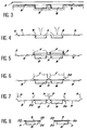
- thermoforming carried out in module 5 to constitute simultaneously a cavity 8 and a cover 9 in the strip 2 of thermoplastic material advancing step by step no predetermined advance according to the dimensions of the corresponding mold.
- the filling is carried out simultaneous cavities 8 by a product P.
- the product P at least partially fills each cavity 8 without however, overflow from it.
- the heat-sealable strip 3 intended to the lidding is applied by welding electrodes E along the contour of each cavity 8 so that constitute by welding a sealing rim of the cover around each cavity 8.
- mobile knives or members equivalent cutting edges cut the first strip 2 of thermoforming according to a longitudinal dotted cut.
- cutting means D perform simultaneously cutting a cavity 8 and a cover 9 associated, while other cutting means A cut in broken lines at the location of a hinge 20 which will be described below.
- knives A cutting lines can be provided in the module precut mentioned in Figure 6.
- the covers 9 come from material with associated cavities 8 and are connected to cavities 8 by a hinge hinge materialized by at least two connection points made of thermoplastic material or thermoformable.
- the application of the sealing film 3 on the strip thermoformed 2 is carried out by means of welding electrodes making welded beads 21 making a junction plane between the sealing film 3 and the thermoformed strip 2.
- welding electrodes making welded beads 21 making a junction plane between the sealing film 3 and the thermoformed strip 2.
- the cover made of material 3 closes the cavity 8 containing the product P when the cover 9 is open, while the cavity 8 is also closable by the cover 9 coming from of material with the cavity 8 ( Figure 11).
- the hinge of articulation 20 is materialized by points of link 23 separated by cutouts in the form of segments of straight lines 24 produced by the cutting means A of the figure 6.
- the various longitudinal cutting techniques or transverse are now well known: example, we will cite the transverse cutting technique at guillotine, cutter cross cut, cutting cross with emitting punch, cross cut by crushing, longitudinal cutting by knife motorized circular, longitudinal cutting by crushing using pneumatic knives, cutting longitudinal shear, etc ...
- Shaped cutting systems i.e. cutting along a corresponding predetermined contour for example at the perimeter of the new cover and the rim plan 24 of the cavity 8, are also well known: as an example, we will mention the shaped cutting system by punch and die in which the punch has the shape final exterior chosen for packaging.
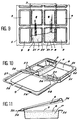
- the new cover snaps onto the flat edge 24 of the cavity 8, it is provided opposite the zone of the material continuity zone corresponding to the points of connection 23, a latching conformation 26 engaging with the flat edge 25, so as to ensure effective sealing of the cavity 8 by the cover 9 even after tearing of the cover of material 3.
- the invention also covers the case where the conformation latching 26 is arranged in another position, by angle example.
- the conformation not only has the conformation 26 but also two adjacent conformations 27 and 28 ensuring snap-in not only on the opposite side of hinge 20, but also on the three other sides of the rectangular outline of the flat edge 25 of cavity 8: it is therefore expected that the conformation total latching formed by the conformations 26, 27 and 28, extends substantially over the entire free perimeter cover 9.
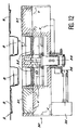
- a mold of thermoforming 30 intended to produce in a strip of material 2 a cover 9, a cavity 8, a second cover 9 and a second associated cavity 8 is constructed modularly by assembling shapes 31 corresponding to covers 9 and shapes 32 corresponding to the cavities 8.
- the assembly is carried out known manner by mechanical mounting by means of screws or of tie rods symbolized by lines of axes V.
- the control of the vertical displacement is carried out by means of a system of column guide 33 and a screw jack 34 controlled by a gearmotor 35 via a bevel gear 36 with gear. Thanks to this advantageous arrangement, it is possible to adjust at will and automatically the depth of the cavities 8 depending on the quantities of P products to be packaged.
- the automaton programmable control is preferably interfaced with the touch screen to display a block tree Entry - Exit with corresponding texts of a share in machine component and block anomalies instantaneous safety shutdown simultaneously stopping all the modules forming part of the device according to the invention.
- the learning and information system incorporated in the PLC and memories appendices provide all the general machine information, all information necessary for maintenance such as cumulative operating times, all information necessary to estimate production such that the accounting of product packaging, all information required to make adjustments adaptable to the types of films or material strips usable thermoplastic (information generally loaded in the form of databases from suppliers of thermoplastics), as well as all the information needed to change and adjust each tool of each module.
Landscapes
- Engineering & Computer Science (AREA)
- Mechanical Engineering (AREA)
- Containers And Plastic Fillers For Packaging (AREA)
- Food Preservation Except Freezing, Refrigeration, And Drying (AREA)
Description
- on préchauffe la première bande de matière thermoplastique entre les étapes a) et b),
- avant l'étape d), on effectue un vide au moins partiel à l'intérieur de la cavité chargée en produits alimentaires, chimiques ou pharmaceutiques,
- on effectue en outre une réinjection de gaz neutre avant la soudure de la deuxième bande de matière thermoplastique ou thermosoudable.
- la cavité est limitée du côté de l'opercule par un rebord plan, et en ce que le couvercle comporte au moins sur le côté opposé a la zone de continuité de matière une conformation d'encliquetage avec ledit rebord plan.
- le couvercle comporte une conformation d'encliquetage avec la cavité.
- la conformation d'encliquetage s'étend sensiblement sur tout le périmètre libre du couvercle.
- les moyens pour saisir par pinçage la première bande comportent des chaínes horizontales portant des pinces à ressort ;
- les moyens pour mettre en forme par thermoformage la première bande de matière thermoplastique comportent un assemblage modulaire de formes correspondant respectivement a un couvercle et a une cavité ;
- la forme correspondant au couvercle est montée en position fixe relativement au corps des moyens de thermoformage.
- la forme correspondant à la cavité est déplaçable relativement au corps des moyens de thermoformage sous l'action d'une commande en translation ;
- le dispositif comporte des moyens de prédécoupe longitudinale de la première bande de matière thermosoudable ;
- le dispositif comporte des moyens de découpe en segments de droite pour constituer la charnière d'articulation.
- la figure 1 représente schématiquement une vue en coupe longitudinale d'un dispositif selon l'invention,
- la figure 2 représente schématiquement une vue de dessus d'un dispositif selon l'invention,
- les figures 3 à 8 représentent schématiquement les étapes successives d'un procédé de conditionnement selon l'invention,
- la figure 9 représente schématiquement une vue de dessus explicitant la mise en oeuvre de l'invention,
- la figure 10 représente schématiquement une vue en perspective avec coupe partielle d'une barquette de conditionnement selon l'invention,
- la figure 11 représente schématiquement en coupe transversale une barquette de conditionnement selon l'invention,
- la figure 12 représente schématiquement une vue en coupe transversale partielle d'un dispositif selon l'invention.
- le système à réinjection par buse dans lequel on maintient le film d'operculage du rouleau 3 en positon retenue pour permettre la réinjection de gaz et dans lequel on utilise une buse couvrant toute la largeur de l'outillage de soudure et effectuant la réinjection de gaz sous le film d'operculage 3 à l'intérieur de la cavité 8,
- ou alternativement la technique de réinjection évoquée plus haut, dite "par pastillage", dans laquelle la bande inférieure préalablement découpée par le module de pastillage 6 permet d'effectuer une réinjection de gaz au moyen de conduits situés en position centrale ou en position latérale du moule de soudure, conduits par lesquels le gaz de réinjection débouche à travers l'emplacement en forme de pastille découpé dans la bande inférieure 2.
Claims (15)
- Procédé de conditionnement de produits alimentaires, chimiques ou pharmaceutiques, comportant en combinaison, les étapes suivantes dans l'ordre suivant :a) saisir par pinçage une première bande (2) de matière thermoplastique ou thermoformable,b) mettre en forme (5) par thermoformage la première bande (2) de matière thermoplastique pour constituer simultanément une cavité (8) et un couvercle (9) associés,c) charger en produits (P) alimentaires, chimiques ou pharmaceutiques ladite cavité (8),d) obturer ladite cavité (8) par soudure d'une deuxième bande (3) de matière thermoplastique ou thermosoudable, de manière a isoler lesdits produits alimentaires, chimiques ou pharmaceutiques (P),e) découper dans la première bande thermoformée à l'étape b) les contours de la cavité (8) et du couvercle (9) de manière a constituer une charnière (20) permettant la fermeture du couvercle (9) sur la cavité (8), obturée à l'étape d), ladite charnière étant matérialisée par au moins deux points de liaison (23), chaque point de liaison étant séparé d'un point de liaison voisin (23) par une découpe en forme de segment de droite (24).
- Procédé selon la revendication 1, caractérisé en ce qu'on préchauffe (4) la première bande (2) de matière thermoplastique entre les étapes a) et b).
- Procédé selon la revendication 1 ou la revendication 2, caractérisé en ce que, avant l'étape d), on effectue un vide au moins partiel à l'intérieur de la cavité (8) chargée en produits alimentaires, chimiques ou pharmaceutiques (P).
- Procédé selon la revendication 3, caractérisé en ce qu'on effectue en outre une réinjection de gaz neutre avant la soudure (12) de la deuxième bande (3) de matière thermoplastique ou thermosoudable.
- Barquette de conditionnement de produits alimentaires, chimiques ou pharmaceutiques, du type comportant une cavité de réception desdits produits et un opercule soudé, la cavité (8) étant thermoformée simultanément avec un couvercle (9) venant de matière avec cette cavité (8), le couvercle (9) étant relié à la cavité (8) par une charnière d'articulation (20), la charnière d'articulation (20) étant matérialisée par au moins deux points (23) de liaison, caractérisée en ce que chaque point de liaison (23) est séparé d'un point de liaison voisin (23) par une découpe en forme de segment de droite (24).
- Barquette selon la revendication 5, caractérisée en ce que la cavité (8) est limitée du côté de l'opercule (3) par un rebord plan (25), et en ce que le couvercle (9) comporte au moins sur le côté opposé a la zone de continuité (20) de matière une conformation d'encliquetage (26) avec ledit rebord plan (25).
- Barquette selon la revendication 5, caractérisée en ce que le couvercle (9) comporte une conformation d'encliquetage (26, 27, 28) avec la cavité (8).
- Barquette selon la revendication 6, caractérisée en ce que la conformation d'encliquetage s'étend sensiblement sur tout le périmètre (26, 27, 28) libre du couvercle (9).
- Dispositif de conditionnement de produits alimentaires, chimiques ou pharmaceutiques, comportant en combinaison des moyens pour saisir par pinçage une première bande (2) de matière thermoplastique ou thermoformable ; des moyens pour mettre en forme (5) par thermoformage la première bande (2) de matière thermoplastique pour constituer simultanément une cavité (8) et un couvercle (9) associés ; des moyens pour charger en produits (P) alimentaires, chimiques ou pharmaceutiques ladite cavité (8) ; des moyens pour obturer ladite cavité (8) par soudure d'une deuxième bande (3) de matière thermoplastique ou thermosoudable, de manière a isoler lesdits produits alimentaires, chimiques ou pharmaceutiques (P) ; et des moyens pour découper dans la première bande les contours de la cavité (8) obturée et du couvercle (9) de manière à constituer une charnière (20) permettant la fermeture du couvercle (9) sur la cavité (8), ladite charnière étant matérialisée par au moins deux points de liaison (23), chaque point de liaison étant séparé d'un point de liaison voisin (23) par une découpe en forme de segment de droite (24).
- Dispositif selon la revendication 9, caractérisé en ce que les moyens pour saisir par pinçage la première bande (2) comportent des chaínes horizontales portant des pinces a ressort.
- Dispositif selon la revendication 9 ou la revendication 10, caractérisé en ce que les moyens pour mettre en forme par thermoformage la première bande (2) de matière thermoplastique comportent un assemblage modulaire de formes (31, 32) correspondant respectivement à un couvercle (9) et a une cavité (8).
- Dispositif selon la revendication 11, caractérisé en ce que la forme (31) correspondant au couvercle (9) est montée en position fixe relativement au corps des moyens de thermoformage.
- Dispositif selon la revendication 11 ou 12, caractérisé en ce que la forme (32) correspondant à la cavité (8) est déplaçable relativement au corps des moyens de thermoformage sous l'action d'une commande (33-36) en translation (T).
- Dispositif selon l'une des revendication 9 à 13, caractérisé en ce que le dispositif comporte des moyens de prédécoupe (C) de la première bande (2) de matière thermoformable.
- Dispositif selon l'une des revendications 9 à 14, caractérisé en ce que le dispositif comporte des moyens (A) de découpe en segments (24) de droite pour constituer la charnière d'articulation (20).
Applications Claiming Priority (2)
| Application Number | Priority Date | Filing Date | Title |
|---|---|---|---|
| FR9313412A FR2712253B1 (fr) | 1993-11-10 | 1993-11-10 | Procédé et dispositif de conditionnement de produits alimentaires, chimiques ou pharmaceutiques et barquettes de conditionnement correspondantes. |
| FR9313412 | 1993-11-10 |
Publications (2)
| Publication Number | Publication Date |
|---|---|
| EP0652155A1 EP0652155A1 (fr) | 1995-05-10 |
| EP0652155B1 true EP0652155B1 (fr) | 1999-03-10 |
Family
ID=9452721
Family Applications (1)
| Application Number | Title | Priority Date | Filing Date |
|---|---|---|---|
| EP19940402366 Expired - Lifetime EP0652155B1 (fr) | 1993-11-10 | 1994-10-21 | Procédé et dispositif de conditionnement de produits alimentaires, chimiques ou pharmaceutiques et barquettes de conditionnement correspondantes |
Country Status (5)
| Country | Link |
|---|---|
| US (1) | US5603203A (fr) |
| EP (1) | EP0652155B1 (fr) |
| DE (1) | DE69416933T2 (fr) |
| ES (1) | ES2131651T3 (fr) |
| FR (1) | FR2712253B1 (fr) |
Families Citing this family (32)
| Publication number | Priority date | Publication date | Assignee | Title |
|---|---|---|---|---|
| KR970075794A (ko) * | 1996-05-16 | 1997-12-10 | 배순훈 | 워터 디스펜서용 물탱크의 외부급수 장치 |
| FR2759352B1 (fr) * | 1997-02-10 | 1999-04-30 | Thierry Roger Garcia | Boite realisee en un seul element, presentant deux receptacles munis de leurs couvercles respectifs se fermant l'un vers l'autre |
| DE19744955A1 (de) * | 1997-10-10 | 1999-04-15 | Bernhard Bartsch Gmbh | Lebensmittelpackung und Verfahren zur Herstellung einer solchen |
| JP3364156B2 (ja) * | 1998-06-05 | 2003-01-08 | ローレルバンクマシン株式会社 | 釣銭作成装置 |
| FR2784654B1 (fr) | 1998-10-16 | 2001-01-12 | Mecaplastic | Procede et dispositif de conditionnement de produits et barquettes de conditionnement correspondantes |
| DE19912491A1 (de) * | 1999-03-19 | 2000-09-28 | Multivac Haggenmueller Gmbh | Verpackungsmaschine |
| IT1311176B1 (it) * | 1999-12-31 | 2002-03-04 | Unifill Internat A G | Sistema di formatura di contenitori per iniezione di un fluidoformatore tra parti di materiale in foglio |
| DE10033796C1 (de) * | 2000-07-12 | 2001-10-11 | Illig Maschinenbau Adolf | Verfahren zum Herstellen von Standblisterpackungen und Vorrichtung zur Durchführung des Verfahrens |
| US20020114543A1 (en) * | 2001-02-20 | 2002-08-22 | Murray R. Charles | Straw pierceable flexible pouch |
| GB2384473B (en) * | 2002-01-24 | 2005-07-27 | Avondale Foods | Packaging apparatus for film-sealing of containers |
| DE10302723A1 (de) * | 2003-01-23 | 2004-08-05 | Iwk Verpackungstechnik Gmbh | Verfahren zur Steuerung einer Blister-Verpackungsmaschine |
| ITMI20030099A1 (it) * | 2003-01-23 | 2004-07-24 | Vacuum Pump Spa | Procedimento, apparato e contenitore per il confezionamento sottovuoto e/o in atmosfera protettiva. |
| DE10302725A1 (de) * | 2003-01-23 | 2004-08-05 | Iwk Verpackungstechnik Gmbh | Blister-Verpackungsmaschine |
| DE10302726A1 (de) * | 2003-01-23 | 2004-08-05 | Iwk Verpackungstechnik Gmbh | Verfahren zur Steuerung einer Blister-Verpackungsmaschine |
| DE102004023474A1 (de) * | 2004-05-12 | 2005-12-15 | Multivac Sepp Haggenmüller Gmbh & Co. Kg | Verpackungsmaschine und Verfahren zum Verschließen von Behältern |
| US7665281B2 (en) * | 2005-07-13 | 2010-02-23 | Cfs Germany Gmbh | Machine for making packaging with form-fit connection |
| US20070138192A1 (en) * | 2005-07-13 | 2007-06-21 | Dietmar Send | Packaging with subsequently molded form-fit connection |
| DE102005038357A1 (de) * | 2005-08-11 | 2007-02-15 | Multivac Sepp Haggenmüller Gmbh & Co. Kg | Verpackungsmaschine mit wenigstens einem Pneumatikantrieb |
| US7308784B2 (en) * | 2005-10-17 | 2007-12-18 | Paul Appelbaum | Apparatus and method for packaging articles in clear plastic packages |
| DE102006020361A1 (de) * | 2006-02-09 | 2007-08-16 | Cfs Germany Gmbh | Verpackungsmaschine für die Herstellung einer Verpackung mit einem Rücksprung in dem Verpackungsmuldenrand |
| DE102006045327A1 (de) * | 2006-09-22 | 2008-04-03 | Cfs Germany Gmbh | Heizplatte mit einer Vielzahl von Heizpatronen |
| DE102006050415A1 (de) * | 2006-10-20 | 2008-04-24 | Cfs Germany Gmbh | Verpackungsmaschine mit einem regelbaren Pneumatik/Hydraulik-Antrieb |
| ES2349481T5 (es) * | 2007-05-04 | 2017-11-15 | Gea Food Solutions Germany Gmbh | Máquina de empaquetar con detección de sustancias extrañas |
| DE102007031527B3 (de) * | 2007-07-06 | 2008-06-19 | Multivac Sepp Haggenmüller Gmbh & Co. Kg | Verpackungsmaschine und Verfahren zum Herstellen von Packungen aus einer Folie |
| EP2253545A1 (fr) * | 2009-05-19 | 2010-11-24 | Ulma Packaging Technological Center, S.Coop. | Machine d'emballage dotée d'un système automatique pour le pliage du rabat de fermeture du paquet et procédé d'emballage |
| WO2013014231A1 (fr) * | 2011-07-28 | 2013-01-31 | Hollister Incorporated | Emballage d'élément de scellement étanche pour stomie et élément de scellement étanche pour stomie associé |
| FR2998503B1 (fr) * | 2012-11-29 | 2014-11-14 | Guillaume Sireix | Procede et machine d'assemblage de corps tubulaires rigides en materiau cartonne avec une structure obturante |
| DE102013204160A1 (de) * | 2013-03-11 | 2014-09-11 | Multivac Sepp Haggenmüller Gmbh & Co. Kg | Verpackungsanlage mit Einraststation und Verfahren |
| NL2018507B1 (nl) * | 2017-03-13 | 2018-09-21 | Conveni B V | Werkwijze voor het maken van een verpakking, verpakking en gebruik ervan |
| DE102019201424A1 (de) * | 2019-02-05 | 2020-08-06 | Multivac Marking & Inspection Gmbh & Co. Kg | Verfahren zum Etikettieren von Verpackungen |
| EP4406876A1 (fr) * | 2023-01-27 | 2024-07-31 | Feral GmbH | Procédé de fabrication de dispositifs de test rapide et dispositif de test rapide |
| CN117885973B (zh) * | 2024-03-18 | 2024-05-31 | 山西宇达青铜文化艺术股份有限公司 | 一种青铜艺术品封装设备 |
Family Cites Families (10)
| Publication number | Priority date | Publication date | Assignee | Title |
|---|---|---|---|---|
| US2958168A (en) * | 1959-05-19 | 1960-11-01 | Clarence W Vogt | Forming and filling containers |
| NL6605663A (fr) * | 1965-04-30 | 1966-10-31 | ||
| US3346099A (en) * | 1966-03-03 | 1967-10-10 | Bristol Myers Co | Moisture-proof container |
| FR1521936A (fr) * | 1967-05-05 | 1968-04-19 | Emballage muni d'un couvercle à charnière | |
| US3958394A (en) * | 1972-01-12 | 1976-05-25 | Mahaffy & Harder Engineering Company | Continuous movement packaging machine |
| FR2268689B1 (fr) * | 1974-04-25 | 1978-09-01 | Erca | |
| US4229927A (en) * | 1978-10-06 | 1980-10-28 | J. Sainsbury Limited | Process and apparatus for vacuum packing |
| US4298133A (en) * | 1979-08-20 | 1981-11-03 | Sweetheart Plastics, Inc. | Integral tray and cover with snap lock |
| US4778048A (en) * | 1987-12-28 | 1988-10-18 | Kimberly-Clark Corporation | Product containing a tilted stack of wet wipes |
| DE3938874A1 (de) * | 1989-11-24 | 1991-05-29 | Tetra Pak Gmbh | Verfahren zur herstellung einer fliessmittelpackung, vorrichtung zur herstellung einer solchen packung und verwendung eines besonderen kunststoffes |
-
1993
- 1993-11-10 FR FR9313412A patent/FR2712253B1/fr not_active Expired - Fee Related
-
1994
- 1994-10-21 ES ES94402366T patent/ES2131651T3/es not_active Expired - Lifetime
- 1994-10-21 EP EP19940402366 patent/EP0652155B1/fr not_active Expired - Lifetime
- 1994-10-21 DE DE69416933T patent/DE69416933T2/de not_active Expired - Lifetime
- 1994-11-07 US US08/337,421 patent/US5603203A/en not_active Expired - Lifetime
Also Published As
| Publication number | Publication date |
|---|---|
| FR2712253A1 (fr) | 1995-05-19 |
| DE69416933D1 (de) | 1999-04-15 |
| EP0652155A1 (fr) | 1995-05-10 |
| ES2131651T3 (es) | 1999-08-01 |
| DE69416933T2 (de) | 2001-02-15 |
| FR2712253B1 (fr) | 1996-01-19 |
| US5603203A (en) | 1997-02-18 |
Similar Documents
| Publication | Publication Date | Title |
|---|---|---|
| EP0652155B1 (fr) | Procédé et dispositif de conditionnement de produits alimentaires, chimiques ou pharmaceutiques et barquettes de conditionnement correspondantes | |
| EP0252791B1 (fr) | Plateau-présentoir perfectionné formant emballage | |
| US4667453A (en) | Method of forming sealed flexible container with non-destructive peelable opening | |
| EP0362102B1 (fr) | Procédé et dispositif pour améliorer la rigidité d'un conteneur en matière synthétique | |
| EP0994021B1 (fr) | Procédé et dispositif de conditionnement de produits et barquette de conditionnement correspondante | |
| KR200495403Y1 (ko) | 플라스틱 필름 밀봉 및 포장 장치 | |
| EP0284529A1 (fr) | Emballage pour le conditionnement de produits sous un film transparent, procédé pour la réalisation de cet emballage et dispositif pour la mise en oeuvre de ce procédé | |
| FR3002207A1 (fr) | Conditionnement d'un groupe d'au moins deux recipients en matiere plastique | |
| EP1312548A1 (fr) | Dispositif pour découper une rangée d'opercules dans une bande à opercules et les fixer sur une rangée de récipients remplis | |
| EP0645309B1 (fr) | Procédé et dispositif pour adapter la hauteur d'un emballage à la hauteur de son contenu et dispositif de coupe pour la mise en oeuvre | |
| FR2503036A1 (fr) | Bande composite a couvercles pour recipients thermoplastiques et procede, dispositif et installation de fabrication d'une telle bande composite | |
| FR2622171A1 (fr) | Procede et appareil pour le conditionnement d'un produit alimentaire ou autre dans une barquette de presentation | |
| EP1521673B1 (fr) | Procede et installation pour la fabrication d'un emballage tubulaire | |
| CH626561A5 (en) | Method for the manufacture of an assembly formed by a covering sheet and a support, device for implementing the method, and container obtained | |
| EP3797968B1 (fr) | Machine de thermoformage, d'operculage et de decoupe de contenants multiformat | |
| EP0062571A1 (fr) | Procédé et dispositif de perçage d'un couvercle de récipient, et installation de fabrication du dispositif | |
| EP1432616B1 (fr) | Dispositif d' operculage d' emballages pour machine de conditionnement sous atmosphere controlee | |
| EP1340678A1 (fr) | Emballage étanche pour produits alimentaires | |
| FR2565552A1 (fr) | Procede et appareil pour le conditionnement de certains produits dans des barquettes ou recipients similaires | |
| EP0099306B1 (fr) | Procédé de fabrication d'articles en matière synthétique obtenus par thermoformage et liés les uns aux autres par des pattes d'accrochage pouvant être facilement rompues et dispositif pour sa mise en oeuvre | |
| EP1690791B1 (fr) | Procédé et installation pour le thermoformage de récipients | |
| WO2006085031A1 (fr) | Procede et installation de conditionnement en poche souple de produits liquides | |
| EP0796793A1 (fr) | Procédé pour la mise en place d'un dispositif d'ouverture et de fermeture d'un emballage | |
| FR2467794A1 (fr) | Emballage ferme en feuille de plastique, son procede de fabrication et installation pour la mise en oeuvre de ce procede | |
| FR2750950A1 (fr) | Procede et dispositif de conditionnement notamment pour pizza a emporter et conditionnement de pizza obtenu |
Legal Events
| Date | Code | Title | Description |
|---|---|---|---|
| PUAI | Public reference made under article 153(3) epc to a published international application that has entered the european phase |
Free format text: ORIGINAL CODE: 0009012 |
|
| AK | Designated contracting states |
Kind code of ref document: A1 Designated state(s): BE CH DE ES GB IT LI |
|
| 17P | Request for examination filed |
Effective date: 19951030 |
|
| 17Q | First examination report despatched |
Effective date: 19961114 |
|
| GRAG | Despatch of communication of intention to grant |
Free format text: ORIGINAL CODE: EPIDOS AGRA |
|
| GRAG | Despatch of communication of intention to grant |
Free format text: ORIGINAL CODE: EPIDOS AGRA |
|
| GRAH | Despatch of communication of intention to grant a patent |
Free format text: ORIGINAL CODE: EPIDOS IGRA |
|
| GRAH | Despatch of communication of intention to grant a patent |
Free format text: ORIGINAL CODE: EPIDOS IGRA |
|
| GRAA | (expected) grant |
Free format text: ORIGINAL CODE: 0009210 |
|
| AK | Designated contracting states |
Kind code of ref document: B1 Designated state(s): BE CH DE ES GB IT LI |
|
| PG25 | Lapsed in a contracting state [announced via postgrant information from national office to epo] |
Ref country code: IT Free format text: LAPSE BECAUSE OF FAILURE TO SUBMIT A TRANSLATION OF THE DESCRIPTION OR TO PAY THE FEE WITHIN THE PRESCRIBED TIME-LIMIT;WARNING: LAPSES OF ITALIAN PATENTS WITH EFFECTIVE DATE BEFORE 2007 MAY HAVE OCCURRED AT ANY TIME BEFORE 2007. THE CORRECT EFFECTIVE DATE MAY BE DIFFERENT FROM THE ONE RECORDED. Effective date: 19990310 |
|
| REG | Reference to a national code |
Ref country code: CH Ref legal event code: EP |
|
| REF | Corresponds to: |
Ref document number: 69416933 Country of ref document: DE Date of ref document: 19990415 |
|
| REG | Reference to a national code |
Ref country code: ES Ref legal event code: FG2A Ref document number: 2131651 Country of ref document: ES Kind code of ref document: T3 |
|
| REG | Reference to a national code |
Ref country code: CH Ref legal event code: NV Representative=s name: PATENTANWALTSBUERO JEAN HUNZIKER |
|
| GBT | Gb: translation of ep patent filed (gb section 77(6)(a)/1977) |
Effective date: 19991103 |
|
| PLAV | Examination of admissibility of opposition |
Free format text: ORIGINAL CODE: EPIDOS OPEX |
|
| PLBQ | Unpublished change to opponent data |
Free format text: ORIGINAL CODE: EPIDOS OPPO |
|
| PLBI | Opposition filed |
Free format text: ORIGINAL CODE: 0009260 |
|
| 26 | Opposition filed |
Opponent name: MULTIVAC SEPP HAGGENMUELLER KG Effective date: 19991209 |
|
| PLAV | Examination of admissibility of opposition |
Free format text: ORIGINAL CODE: EPIDOS OPEX |
|
| PLBF | Reply of patent proprietor to notice(s) of opposition |
Free format text: ORIGINAL CODE: EPIDOS OBSO |
|
| PLBL | Opposition procedure terminated |
Free format text: ORIGINAL CODE: EPIDOS OPPC |
|
| PLBM | Termination of opposition procedure: date of legal effect published |
Free format text: ORIGINAL CODE: 0009276 |
|
| STAA | Information on the status of an ep patent application or granted ep patent |
Free format text: STATUS: OPPOSITION PROCEDURE CLOSED |
|
| 27C | Opposition proceedings terminated |
Effective date: 20001113 |
|
| REG | Reference to a national code |
Ref country code: GB Ref legal event code: IF02 |
|
| PGFP | Annual fee paid to national office [announced via postgrant information from national office to epo] |
Ref country code: DE Payment date: 20101022 Year of fee payment: 17 |
|
| PGFP | Annual fee paid to national office [announced via postgrant information from national office to epo] |
Ref country code: GB Payment date: 20101021 Year of fee payment: 17 |
|
| PGFP | Annual fee paid to national office [announced via postgrant information from national office to epo] |
Ref country code: ES Payment date: 20111026 Year of fee payment: 18 Ref country code: CH Payment date: 20111024 Year of fee payment: 18 Ref country code: BE Payment date: 20111021 Year of fee payment: 18 |
|
| BERE | Be: lapsed |
Owner name: *MECAPLASTIC Effective date: 20121031 |
|
| REG | Reference to a national code |
Ref country code: CH Ref legal event code: PL |
|
| GBPC | Gb: european patent ceased through non-payment of renewal fee |
Effective date: 20121021 |
|
| PG25 | Lapsed in a contracting state [announced via postgrant information from national office to epo] |
Ref country code: BE Free format text: LAPSE BECAUSE OF NON-PAYMENT OF DUE FEES Effective date: 20121031 Ref country code: LI Free format text: LAPSE BECAUSE OF NON-PAYMENT OF DUE FEES Effective date: 20121031 Ref country code: CH Free format text: LAPSE BECAUSE OF NON-PAYMENT OF DUE FEES Effective date: 20121031 Ref country code: GB Free format text: LAPSE BECAUSE OF NON-PAYMENT OF DUE FEES Effective date: 20121021 Ref country code: DE Free format text: LAPSE BECAUSE OF FAILURE TO SUBMIT A TRANSLATION OF THE DESCRIPTION OR TO PAY THE FEE WITHIN THE PRESCRIBED TIME-LIMIT Effective date: 20130501 |
|
| REG | Reference to a national code |
Ref country code: DE Ref legal event code: R119 Ref document number: 69416933 Country of ref document: DE Effective date: 20130501 |
|
| REG | Reference to a national code |
Ref country code: ES Ref legal event code: FD2A Effective date: 20140116 |
|
| PG25 | Lapsed in a contracting state [announced via postgrant information from national office to epo] |
Ref country code: ES Free format text: LAPSE BECAUSE OF NON-PAYMENT OF DUE FEES Effective date: 20121022 |