EP0652158A1 - Dispositif pour tenir une bouteille essentiellement cylindrique - Google Patents
Dispositif pour tenir une bouteille essentiellement cylindrique Download PDFInfo
- Publication number
- EP0652158A1 EP0652158A1 EP93810776A EP93810776A EP0652158A1 EP 0652158 A1 EP0652158 A1 EP 0652158A1 EP 93810776 A EP93810776 A EP 93810776A EP 93810776 A EP93810776 A EP 93810776A EP 0652158 A1 EP0652158 A1 EP 0652158A1
- Authority
- EP
- European Patent Office
- Prior art keywords
- bottle
- holding means
- holding
- handle
- ring
- Prior art date
- Legal status (The legal status is an assumption and is not a legal conclusion. Google has not performed a legal analysis and makes no representation as to the accuracy of the status listed.)
- Withdrawn
Links
- 235000013361 beverage Nutrition 0.000 claims abstract description 7
- 239000011324 bead Substances 0.000 claims description 5
- 230000002093 peripheral effect Effects 0.000 claims description 3
- 239000007788 liquid Substances 0.000 abstract description 8
- 210000003811 finger Anatomy 0.000 abstract description 4
- 210000003813 thumb Anatomy 0.000 abstract description 3
- 230000000694 effects Effects 0.000 description 3
- 230000003014 reinforcing effect Effects 0.000 description 3
- 238000010276 construction Methods 0.000 description 2
- 239000000463 material Substances 0.000 description 2
- 230000002950 deficient Effects 0.000 description 1
- 238000004512 die casting Methods 0.000 description 1
- 238000006073 displacement reaction Methods 0.000 description 1
- 238000005516 engineering process Methods 0.000 description 1
- 230000002787 reinforcement Effects 0.000 description 1
- 230000035807 sensation Effects 0.000 description 1
Images

Classifications
-
- B—PERFORMING OPERATIONS; TRANSPORTING
- B65—CONVEYING; PACKING; STORING; HANDLING THIN OR FILAMENTARY MATERIAL
- B65D—CONTAINERS FOR STORAGE OR TRANSPORT OF ARTICLES OR MATERIALS, e.g. BAGS, BARRELS, BOTTLES, BOXES, CANS, CARTONS, CRATES, DRUMS, JARS, TANKS, HOPPERS, FORWARDING CONTAINERS; ACCESSORIES, CLOSURES, OR FITTINGS THEREFOR; PACKAGING ELEMENTS; PACKAGES
- B65D23/00—Details of bottles or jars not otherwise provided for
- B65D23/10—Handles
- B65D23/104—Handles formed separately
- B65D23/106—Handles formed separately the gripping region of the handle extending between the neck and the base of the bottle or jar and being located in a radial plane comprising the axis of the bottle or jar
-
- A—HUMAN NECESSITIES
- A47—FURNITURE; DOMESTIC ARTICLES OR APPLIANCES; COFFEE MILLS; SPICE MILLS; SUCTION CLEANERS IN GENERAL
- A47G—HOUSEHOLD OR TABLE EQUIPMENT
- A47G23/00—Other table equipment
- A47G23/02—Glass or bottle holders
- A47G23/0241—Glass or bottle holders for bottles; Decanters
Definitions
- the present invention relates to a device for holding a substantially cylindrical bottle according to the preamble of claim 1.
- the invention relates to a device for holding beverage bottles, which are made of plastic, preferably PET.
- PET bottles are hardly compressible before opening for the first time due to an internal pressure. When you touch them, they give the impression of a rigid structure. When the screw cap is opened, for which the bottle has to be firmly gripped with one hand, the internal pressure can suddenly escape. This suddenly makes the material unstable and soft. A sudden squeeze often results in an unwanted pouring of liquid or even a slipping of the bottle out of your hand.
- the invention solves this problem with a device having the features listed in the characterizing part of claim 1.
- Known holding devices for bottles are constructed in such a way that the bottle is placed in a basket-like holder and by means of a ring which is pushed over the bottle neck and which is connected to the basket-like holder, for example by means of two springs, bands or chains. is held relatively loosely in the holding device.
- a handle which is usually present on the known holding device, the wine can be poured out by pivoting the latter.
- Such known devices are often not very functional, since they usually represent an ornament for a covered table.
- the object of the present invention is not only to develop a holding device from an aesthetic point of view, but also to provide it with technical features in such a way that it is really optimally used in every respect.
- the invention is based on the fact that the device can be attached to the bottle to be held with as little play as possible. This is achieved on the one hand with the relatively rigid web with which the two holding means are connected to one another, and on the other hand in that one of the holding means is intended to at least partially enclose a peripheral region of the bottle in a tight fit.
- a second holding means comes to lie in the region of the middle third of the height of a bottle. It can be designed as a ring which is pushed over the bottle from above when the device is attached, until the first holding means lies in the region of the bottle neck and can be attached to it.
- it is the first holding means in the area of the bottle neck which is intended to at least partially enclose a peripheral area of the bottle in a tight fit.
- the second holding means could also be designed as a partial ring which can be placed in the radial direction over the outer surface of the bottle, the partial ring, which preferably represents approximately half of a ring, can be connected at its two ends to a band-shaped element.
- the band-shaped element can be a ribbon, a piece of which is attached to each end of the partial ring or it can be an elastic band or preferably a Velcro fastener, a Velcro fastener tape being attached to one end of the partial ring and the counterpart of the Velcro fastener being attached to the other end of the partial ring .
- the second holding means could of course also be designed as a ring, which is arranged in the area of the bottle base, or as a bowl into which the bottle would be placed.
- a solution depends on the bottle height and is not generally applicable to all bottles.
- the first holding device in the area of the bottle neck is preferably formed as a clip with two elastic arms, which can be placed in the radial direction around the bottle neck of the bottle to be held.
- the fact that the two arms together enclose more than half of the circumference of the bottle neck creates the effect of the first holding means snapping onto the bottle neck.
- the first holding means extends in the axial direction of the bottle over a range from a bottle shoulder to a bead which surrounds the bottle neck on the outlet side. In the case of a PET bottle, this area is very pronounced and only has a length of a few millimeters.
- the first holding means can be designed such that it is not possible to move it in the axial direction of the bottle neck. An additional good adhesion of the device to the bottle is thereby achieved.
- the device with a first holding means designed as a clamp and a second holding means designed as a ring can be attached and removed very easily to the bottle to be held. To attach it, simply slide the ring over the bottle from above and then snap the second holding device over the bottle neck. The removal of the holding device is just as easy in reverse order.
- a handle extends along the web, which connects the two holding means relatively rigidly to one another. This is spaced from the web in the radial direction and spreads in the longitudinal direction of the bottle to be held approximately over the middle third of the bottle height. In this way it is achieved that when the liquid is poured out, the bottle tilts about a pivot axis which is approximately in the middle of the bottle height lies. This allows the liquid to be poured out with the least amount of force. It is not necessary, in addition to the lifting force, to exert a pronounced pivoting force, as would be necessary if the handle was attached too high, for example in the area of the bottle neck, or to counteract an excessive pivoting tendency, as would be required if the handle was attached too deep .
- a support element is provided at the top of the web in the area of the first holding means, which is essentially designed as a support ring and thanks to which it is possible to easily carry several PET bottles, for example one each with a finger.
- the handle only protrudes so far from the dock that bottles can be lined up next to each other without any significant loss of space. This is the case when the handles are held at an angle of approximately 45 ° relative to the row of bottles.
- a minimal loss of space arises only from the small wall thickness of the ring of the second holding means, which surrounds the outer surface of the bottle.
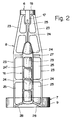
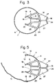
- FIGS. 1, 2 and 3 A preferred first embodiment of the device according to the invention is shown in FIGS. 1, 2 and 3.
- a so-called PET bottle is drawn. This is essentially cylindrical and tapers at the top, forming a bottle shoulder 21, to form a bottle neck 3, to which a spout 4 is connected.
- a circumferential bead 22 separates the spout 4 from the bottle neck 3.
- the spout 4 usually has an external thread on which the PET bottle can be closed by means of a screw cap.
- the holding device comprises a first holding means 6, which is arranged in the area of the bottle neck 3, and a second holding means 7, which in the device attached to the bottle comes to lie approximately in the middle third of the height of the bottle to be held.
- the two holding means 6, 7 are relatively rigidly connected to one another by means of a web 8. The axial distance between the two holding means is therefore unchangeable.
- the first holding means 6 is designed as a clip 18, which clip has a first arm 19 and a second arm 20.
- the bracket 18 is designed in such a way that the two arms mentioned form a pitch circle and include an inner diameter which essentially corresponds to the diameter of the bottle neck 3 of the bottle to be held.
- the two arms 19, 20 are elastic to one another and can be placed around the latter with a movement radially directed towards the bottle neck. Since the two arms 19, 20 surround the bottle neck 3 together more than half and, as already mentioned, are of elastic design, the first holding means snaps onto the bottle neck 3 when the aforementioned movement is carried out.
- the web 8 extends along the bottle to be held and preferably lies over its entire length on the outer wall of the bottle.
- the bottle neck 3 is only a few millimeters long in PET bottles. It is limited on one side by the already mentioned circumferential bead 22 which separates the bottle neck 3 from the spout 4 and by the pronounced shoulder 21.
- a good holding effect or adhesion of the device according to the invention attached to the bottle to be held is not only achieved by that the two arms 19, 20 of the clamp 18 mentioned tightly enclose a part of the bottle neck, but is additionally improved, if the first holding means 6 extends in the axial direction of the bottle over the entire bottle neck, ie over the area between the bead 22 and the bottle shoulder 21. The possibility of an axial displacement of the holding device is thereby prevented.
- the second holding means 7 comprises a ring 9 which has an inner diameter which is only slightly larger than the outer diameter of the cylindrical outer surface of the bottle 1.
- the ring 9 is dimensioned such that it is used to attach the device to the bottle to be held can be easily guided over the bottle from above until the second holding means 6, the clip 18, is in the region of the bottle neck 3, via which the clip 18 can be snapped in, as already described.
- the web 8, which connects the two holding means 6, 9, essentially comprises a plurality of ribs 23 spaced apart from one another and extending in the axial direction of the bottle to be held, and a plurality of ribs 24 extending in the circumferential direction of the bottle to be held, which ribs 23 , 24 are connected to one another and include openings designated by 25.
- the web 8 can be formed relatively rigidly and yet easily.
- provision can also be made for the web to be of full surface and relatively thin-walled design.
- a handle 16 extends along the web 8. It is raised in the radial direction from the web 8.
- the handle 16 also comprises ribs 23 extending in the axial direction of the bottle and ribs 24 'arranged at right angles thereto. It extends from an upper reinforcing flange 27, which is connected approximately centrally between the first holding means 6 and the second holding means 7 to the web 8, to a lower reinforcing flange 28, which is arranged in the region of the second holding means 7 on the web 8.
- the handle 16 and the two reinforcing flanges 27, 28 mentioned include a holding opening 29 which is intended for the passage of the fingers of a hand of a person lifting the bottle.
- the handle 16 lies optimally in the hand, its ribs 24 'are bent essentially in the opposite direction to the surface of the bottle.
- the ribs 23 and 24 'of the handle 16 preferably do not include any openings in the exemplary embodiment shown, but only serve for reinforcement.
- a smooth, curved surface can be felt by the hand.
- a thumb pan 26 is provided for placing the thumb.
- a pivoting movement of the bottle about a pivot axis which is approximately in the center of the bottle height is achieved in that the handle 16 extends approximately over a length substantially parallel to the web, which covers approximately the middle third of the bottle height. It is possible to pour the liquid out of the bottle with the least possible effort.
- a support element 17 is provided, which is preferably designed as a support ring.
- the support ring 17 includes a support opening 30 which is dimensioned so large that it can be easily penetrated with a finger to carry the bottle. Thanks to the support ring arranged at the top of the holding device, it is possible to carry several PET bottles, each provided with a holding device, with one hand.
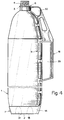
- FIG. 4 shows a further exemplary embodiment, in which only the second holding means 7 compared to the exemplary embodiment already described is changed.
- This no longer comprises a closed ring, but only has a partial ring 10 thereof.
- a band-shaped element 11 is fastened to a partial ring end 13, for example a Velcro fastener tape, and a counterpart 11 ′ of the Velcro fastener is attached to the other partial ring end 12.
- the Velcro fastener tape 11 is closed tightly around the outer surface of the bottle.
- the holding device according to the invention in such a way that, by the web 8 being extended, the second holding means 7 would have to be placed in the area of the bottle base 2. It could either be designed as a ring 14 or, as indicated by dash-dotted lines, as a bowl 15, in which ring 14 or in which bowl 15 the bottle base 2 would be located. A special holding device would have to be created for each bottle height.
- the holding devices shown are manufactured in one piece using plastic die-casting technology. PET is also used as the preferred material. This also ensures that holding devices that are no longer used or have gone defective can be disposed of in the same way as the PET bottles.
Landscapes
- Engineering & Computer Science (AREA)
- Mechanical Engineering (AREA)
- Details Of Rigid Or Semi-Rigid Containers (AREA)
Priority Applications (1)
| Application Number | Priority Date | Filing Date | Title |
|---|---|---|---|
| EP93810776A EP0652158A1 (fr) | 1993-11-09 | 1993-11-09 | Dispositif pour tenir une bouteille essentiellement cylindrique |
Applications Claiming Priority (1)
| Application Number | Priority Date | Filing Date | Title |
|---|---|---|---|
| EP93810776A EP0652158A1 (fr) | 1993-11-09 | 1993-11-09 | Dispositif pour tenir une bouteille essentiellement cylindrique |
Publications (1)
| Publication Number | Publication Date |
|---|---|
| EP0652158A1 true EP0652158A1 (fr) | 1995-05-10 |
Family
ID=8215062
Family Applications (1)
| Application Number | Title | Priority Date | Filing Date |
|---|---|---|---|
| EP93810776A Withdrawn EP0652158A1 (fr) | 1993-11-09 | 1993-11-09 | Dispositif pour tenir une bouteille essentiellement cylindrique |
Country Status (1)
| Country | Link |
|---|---|
| EP (1) | EP0652158A1 (fr) |
Cited By (11)
| Publication number | Priority date | Publication date | Assignee | Title |
|---|---|---|---|---|
| WO1998019926A1 (fr) * | 1996-11-01 | 1998-05-14 | The Mead Corporation | Poignee de bouteille |
| LT5134B (lt) | 2003-07-29 | 2004-05-25 | Uab "Natūralios Sultys" | Butelio laikiklis |
| US6913159B1 (en) | 2003-03-10 | 2005-07-05 | Robert H. Goldberg | Water bottle strap with finger holes |
| GB2461034A (en) * | 2008-06-17 | 2009-12-23 | Basem Halwani | Bottle holder |
| US7726499B2 (en) * | 2005-06-07 | 2010-06-01 | Innovative Household Products, Inc. | Bottle holder |
| DE102010007903A1 (de) | 2010-02-13 | 2011-08-18 | Verena 40237 Brucklacher | Individuell anpassbare Vorrichtung (Behälter) für Ein- oder Mehrwegflaschen |
| DE202015103777U1 (de) | 2015-07-17 | 2015-09-18 | Krones Ag | Additiv-Griff für Großbehälter |
| USD796903S1 (en) | 2016-06-03 | 2017-09-12 | Shock Doctor, Inc. | Hydration bladder |
| WO2017209764A1 (fr) * | 2016-06-03 | 2017-12-07 | Shock Doctor, Inc. | Vessie d'hydratation à main |
| USD806476S1 (en) | 2016-06-03 | 2018-01-02 | Shock Doctor, Inc. | Hydration bladder |
| US10582760B1 (en) | 2018-09-11 | 2020-03-10 | James Kardoosh | Container pouring assist system |
Citations (10)
| Publication number | Priority date | Publication date | Assignee | Title |
|---|---|---|---|---|
| GB1015832A (en) * | 1964-01-16 | 1966-01-05 | Robert Frederick Wiles | Improvements in bottle and flask holders |
| US4379578A (en) * | 1980-03-03 | 1983-04-12 | Heriberto Schuler | Reusable bottle holder |
| US4660876A (en) * | 1986-01-15 | 1987-04-28 | Beverage Mate Corp. | Reusable bottle handle |
| US4666197A (en) * | 1986-04-16 | 1987-05-19 | Watson Wayne R | Bottle holder |
| US4667359A (en) * | 1985-01-15 | 1987-05-26 | Enzo Polotti | Universal grip device particularly for generic bottles and the like container |
| US4834438A (en) * | 1988-09-09 | 1989-05-30 | Haidet Donald A | Device for lifting and inverting cylindrical containers |
| US4842158A (en) * | 1988-02-19 | 1989-06-27 | Reyes Jr Ruben | Container handle attachment |
| US4896913A (en) * | 1988-09-19 | 1990-01-30 | Kennedy Steve J | Releasable self locking handle for wide body, narrow neck containers |
| US4972964A (en) * | 1989-10-17 | 1990-11-27 | Escalante Frank A | Bottle holder |
| EP0524328A1 (fr) * | 1991-03-12 | 1993-01-27 | RIPA di Risi Paolo | Dispositif pour supporter les boutteilles |
-
1993
- 1993-11-09 EP EP93810776A patent/EP0652158A1/fr not_active Withdrawn
Patent Citations (10)
| Publication number | Priority date | Publication date | Assignee | Title |
|---|---|---|---|---|
| GB1015832A (en) * | 1964-01-16 | 1966-01-05 | Robert Frederick Wiles | Improvements in bottle and flask holders |
| US4379578A (en) * | 1980-03-03 | 1983-04-12 | Heriberto Schuler | Reusable bottle holder |
| US4667359A (en) * | 1985-01-15 | 1987-05-26 | Enzo Polotti | Universal grip device particularly for generic bottles and the like container |
| US4660876A (en) * | 1986-01-15 | 1987-04-28 | Beverage Mate Corp. | Reusable bottle handle |
| US4666197A (en) * | 1986-04-16 | 1987-05-19 | Watson Wayne R | Bottle holder |
| US4842158A (en) * | 1988-02-19 | 1989-06-27 | Reyes Jr Ruben | Container handle attachment |
| US4834438A (en) * | 1988-09-09 | 1989-05-30 | Haidet Donald A | Device for lifting and inverting cylindrical containers |
| US4896913A (en) * | 1988-09-19 | 1990-01-30 | Kennedy Steve J | Releasable self locking handle for wide body, narrow neck containers |
| US4972964A (en) * | 1989-10-17 | 1990-11-27 | Escalante Frank A | Bottle holder |
| EP0524328A1 (fr) * | 1991-03-12 | 1993-01-27 | RIPA di Risi Paolo | Dispositif pour supporter les boutteilles |
Cited By (15)
| Publication number | Priority date | Publication date | Assignee | Title |
|---|---|---|---|---|
| WO1998019926A1 (fr) * | 1996-11-01 | 1998-05-14 | The Mead Corporation | Poignee de bouteille |
| US6913159B1 (en) | 2003-03-10 | 2005-07-05 | Robert H. Goldberg | Water bottle strap with finger holes |
| LT5134B (lt) | 2003-07-29 | 2004-05-25 | Uab "Natūralios Sultys" | Butelio laikiklis |
| US7726499B2 (en) * | 2005-06-07 | 2010-06-01 | Innovative Household Products, Inc. | Bottle holder |
| GB2461034A (en) * | 2008-06-17 | 2009-12-23 | Basem Halwani | Bottle holder |
| GB2461034B (en) * | 2008-06-17 | 2010-04-28 | Basem Halwani | A bottle holder |
| DE102010007903A1 (de) | 2010-02-13 | 2011-08-18 | Verena 40237 Brucklacher | Individuell anpassbare Vorrichtung (Behälter) für Ein- oder Mehrwegflaschen |
| DE202015103777U1 (de) | 2015-07-17 | 2015-09-18 | Krones Ag | Additiv-Griff für Großbehälter |
| USD796903S1 (en) | 2016-06-03 | 2017-09-12 | Shock Doctor, Inc. | Hydration bladder |
| WO2017209764A1 (fr) * | 2016-06-03 | 2017-12-07 | Shock Doctor, Inc. | Vessie d'hydratation à main |
| USD806476S1 (en) | 2016-06-03 | 2018-01-02 | Shock Doctor, Inc. | Hydration bladder |
| USD841399S1 (en) | 2016-06-03 | 2019-02-26 | Shock Doctor, Inc. | Hydration bladder |
| USD892554S1 (en) | 2016-06-03 | 2020-08-11 | Shock Doctor, Inc. | Hydration bladder |
| US11357314B2 (en) | 2016-06-03 | 2022-06-14 | Shock Doctor, Inc. | Hand-carried hydration bladder |
| US10582760B1 (en) | 2018-09-11 | 2020-03-10 | James Kardoosh | Container pouring assist system |
Similar Documents
| Publication | Publication Date | Title |
|---|---|---|
| DE3036139C2 (fr) | ||
| EP0472915B2 (fr) | Distributeur de fluide | |
| DE2934711A1 (de) | Wiederverschliessbarer fluessigkeits- behaelter | |
| EP0814693B1 (fr) | Broc pour liquides | |
| EP0543111A2 (fr) | Support pour distributeurs d'épices | |
| CH644678A5 (de) | Dispenserventil, insbesondere fuer viskoese produkte. | |
| EP0652158A1 (fr) | Dispositif pour tenir une bouteille essentiellement cylindrique | |
| DE69025320T2 (de) | Flasche mit Tropfvorrichtung | |
| DE2917150C2 (de) | Verschlußdeckel | |
| DE69100582T2 (de) | Betätigungsvorrichtung für Ausgabeventil. | |
| DE69308447T2 (de) | Pumpen Tragering für einen Spenderbehälter, Ausgabeanordnung dafür und Verfahren zum Füllen derselben | |
| EP0538573A2 (fr) | Fermeture de récipient à encliquetage | |
| DE69007967T2 (de) | Nichtlösbare eingerastete Kappe für Spender. | |
| DE9204076U1 (de) | Verschluß für Tuben oder dergleichen | |
| DE2524290A1 (de) | Ausgabe-handgeraet mit pumpenbetaetigung | |
| DE20120142U1 (de) | Sprühdose | |
| DE2738735A1 (de) | Halter fuer flaschen, insbesondere infusionsflaschen | |
| DE3507133A1 (de) | Aerosolspender | |
| DE3327880C2 (fr) | ||
| DE4442382A1 (de) | Dispensierkappe | |
| EP2431294B1 (fr) | Fermeture rotative pour récipients cosmétiques | |
| EP2707304B1 (fr) | Fermeture de sécurité pour enfants réalisée en deux parties | |
| DE3007820C2 (de) | Metalltube | |
| DE3241044A1 (de) | Aufsetzbare abgiessvorrichtung fuer flaschen, insbesondere speiseoelflaschen | |
| DE8812474U1 (de) | Flüssigkeits-Aufbewahrungs- und -Ausgabeflasche |
Legal Events
| Date | Code | Title | Description |
|---|---|---|---|
| PUAI | Public reference made under article 153(3) epc to a published international application that has entered the european phase |
Free format text: ORIGINAL CODE: 0009012 |
|
| AK | Designated contracting states |
Kind code of ref document: A1 Designated state(s): AT CH DE FR GB IE IT LI |
|
| RBV | Designated contracting states (corrected) |
Designated state(s): AT CH DE FR GB IE IT LI |
|
| 17P | Request for examination filed |
Effective date: 19951023 |
|
| STAA | Information on the status of an ep patent application or granted ep patent |
Free format text: STATUS: THE APPLICATION IS DEEMED TO BE WITHDRAWN |
|
| 18D | Application deemed to be withdrawn |
Effective date: 19960531 |