EP0652401A2 - Lampadaire avec dispositif de fixation à un mât - Google Patents
Lampadaire avec dispositif de fixation à un mât Download PDFInfo
- Publication number
- EP0652401A2 EP0652401A2 EP94112387A EP94112387A EP0652401A2 EP 0652401 A2 EP0652401 A2 EP 0652401A2 EP 94112387 A EP94112387 A EP 94112387A EP 94112387 A EP94112387 A EP 94112387A EP 0652401 A2 EP0652401 A2 EP 0652401A2
- Authority
- EP
- European Patent Office
- Prior art keywords
- luminaire
- flange
- mast
- lamp
- connecting piece
- Prior art date
- Legal status (The legal status is an assumption and is not a legal conclusion. Google has not performed a legal analysis and makes no representation as to the accuracy of the status listed.)
- Granted
Links
- 238000010276 construction Methods 0.000 claims 1
- 238000011161 development Methods 0.000 description 1
- 230000018109 developmental process Effects 0.000 description 1
- 238000009434 installation Methods 0.000 description 1
- 230000009191 jumping Effects 0.000 description 1
- 238000004519 manufacturing process Methods 0.000 description 1
- 238000000034 method Methods 0.000 description 1
- 230000002441 reversible effect Effects 0.000 description 1
Images

Classifications
-
- F—MECHANICAL ENGINEERING; LIGHTING; HEATING; WEAPONS; BLASTING
- F21—LIGHTING
- F21V—FUNCTIONAL FEATURES OR DETAILS OF LIGHTING DEVICES OR SYSTEMS THEREOF; STRUCTURAL COMBINATIONS OF LIGHTING DEVICES WITH OTHER ARTICLES, NOT OTHERWISE PROVIDED FOR
- F21V21/00—Supporting, suspending, or attaching arrangements for lighting devices; Hand grips
- F21V21/10—Pendants, arms, or standards; Fixing lighting devices to pendants, arms, or standards
- F21V21/116—Fixing lighting devices to arms or standards
-
- F—MECHANICAL ENGINEERING; LIGHTING; HEATING; WEAPONS; BLASTING
- F21—LIGHTING
- F21S—NON-PORTABLE LIGHTING DEVICES; SYSTEMS THEREOF; VEHICLE LIGHTING DEVICES SPECIALLY ADAPTED FOR VEHICLE EXTERIORS
- F21S8/00—Lighting devices intended for fixed installation
- F21S8/08—Lighting devices intended for fixed installation with a standard
-
- F—MECHANICAL ENGINEERING; LIGHTING; HEATING; WEAPONS; BLASTING
- F21—LIGHTING
- F21W—INDEXING SCHEME ASSOCIATED WITH SUBCLASSES F21K, F21L, F21S and F21V, RELATING TO USES OR APPLICATIONS OF LIGHTING DEVICES OR SYSTEMS
- F21W2131/00—Use or application of lighting devices or systems not provided for in codes F21W2102/00-F21W2121/00
- F21W2131/10—Outdoor lighting
- F21W2131/103—Outdoor lighting of streets or roads
Definitions
- the invention relates to an outdoor lamp according to the preamble of claim 1 and in particular a device for fastening it to a mast.
- a connecting piece between the lamp housing and the mast end in this known solution is an assembly member provided that has an angular cover piece, on the outside of which a sleeve is attached, with which the lamp can be placed on a mast end.
- the cover piece on the outside of the housing rests against both its lower wall and its rear wall and screwed on covering the two housing openings.
- the lower wall and the rear wall of the housing form an angle of 90 ° to 105 ° at the point at which the cover piece is arranged, and the mounting element is designed so that the figure axis of the external sleeve is almost vertical runs to one of these walls.
- the mounting member can be used both for post-top and post-top luminaires.
- the invention is therefore based on the object of specifying a further solution for an outdoor lamp with a device for mast mounting of the type mentioned, which can be used universally, allows simple mounting of the lamp even with different angles of inclination and thereby enables a reliable connection between lamp and mast end .
- the connecting piece can also be oriented by rotating the lamp housing by 180 ° in such a way that it is suitable for both types of fastening, in any case completely covering the lamp opening.
- this mast attachment is designed so that it can be adjusted in its angle of inclination with respect to the longitudinal axis of the lamp in an angular range that covers the angle of inclination of the lamp with respect to the road surface that occurs in practice.
- This solution according to the invention also allows a pre-assembly of the lamp, in which the connector on the lamp housing is already fixed so that the pre-assembled lamp, for example from a work platform, is only pushed onto the mast end after cable entry into the mast and there by tightening one Fixing screw must be set.
- this device can also be designed such that it centers itself on the lamp housing and is therefore particularly easy to install.
- an assembly aid can be provided for an exact adjustment of the inclination angle, so that a special adjustment process is unnecessary here. All of these configurations are such that the installation position once selected is reversible, ie the lamp can be installed in a different position at any time, for example when converting the lighting system, with the aid of the newly set connecting piece.
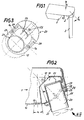
- a street lamp is shown schematically with a lamp body 1, which is placed on a fixture 2 for mast mounting on the end of a lamp mast 3 and firmly connected to this.
- a rounding of the mast-side wall of the lamp body 1 and a corresponding configuration of the contact surface of the device 2 for mast attachment to the lamp body 1 is shown schematically and highlighted by a double arrow labeled ⁇ that the lamp body 1 is to be arranged in relation to this device 2 for mast mounting by this same active ⁇ .
- FIG. 2 shows a cross section of a section from FIG. 1, which is intended to illustrate in particular the design of the device 2 for mast attachment.
- This cross-sectional illustration clearly shows that the housing 10 of the lamp body 1 is rounded in a circular arc on the wall part facing the lamp mast 3.
- a luminaire opening 11 is formed in the lower quadrant of this housing part by housing wall parts which recess inwards and which almost completely fills this quadrant.
- An inner wall of this lamp opening 11 has an opening 12 for the cable feed into the lamp.
- this lamp opening 11, as indicated in Figure 2 by an arrow labeled III, IV, is again shown in a schematic side view.
- This view in conjunction with FIG. 2 shows that the lamp housing 10, comprising the lamp opening 11 on all sides, here jumping back approximately by the thickness of the housing wall, is pulled inwards.
- a curved contact surface 13 is formed in the luminaire housing 10 in the region of the luminaire opening 11 and has a radius R in the plane perpendicular to the longitudinal plane of the luminaire.
- a connecting piece 20, as a further functionally essential part of the device 2 for mast attachment, has a central tube flange 21 which is covered on the light side by a perforated base plate 22 and is open at the outer end for receiving the mast end 31, indicated by dash-dotted lines in FIG. 2 .
- a curved collar Surrounding this pipe flange 21 on the outside, a curved collar is attached to it, which corresponds to the contact surface 13 of the lamp housing in the curvature and forms a fastening flange 23 of the connecting piece 20.
- FIG. 3 as indicated by the arrow III, IV in FIG. 2, a side view of this connecting piece 20 is shown in detail.
- This view illustrates that in the mounting flange 23 to, both sides of the pipe flange 21 slots 24 are provided. These take up fastening screws 14 which engage in threaded bores 15 in the contact surface 13 of the lamp housing 10.
- FIGS 2 and 3 also show that the mounting flange 23 is attached to the pipe flange 21 of the connector 20 via stiffening ribs 25, which include a mounting eye 26, stiffened.
- this fastening eye 26 there is a groove 27 running parallel to the outer wall of the pipe flange 21, into which a threaded nut 28, is rotatably fixed, inserted.
- the fastening eye 26 also has a through hole running perpendicular to the side wall of the tube flange 21. This through hole receives an Allen screw 29, which is screwed into the threaded nut 28 and thereby fixes the connecting piece 20 to the mast end 31 by tensioning the pipe flange 21 with respect to the mast end 31 used.
- FIG. 5 shows a detail of the connection of the fastening flange 23 to the lamp housing 10 in a section which is parallel to the sectional view in FIG. 2.
- This illustration shows that an outwardly projecting knob 17 is provided in the contact surface 13, in the area of the threaded bores 15 embedded in it.
- the outer contour of this knob 17 corresponds to a plurality of groove-shaped recesses 16 on the mounting flange 23.
- this embodiment serves to fix the connecting piece 20 on Luminaire housing 10 as an adjustment aid for determining the angle of inclination ⁇ when mounting the luminaire and as a safeguard against the connecting piece 20 slipping relative to the luminaire housing 10.
- the device for mast attachment described enables the light to be preassembled conveniently, because in every application it is determined for the assembly which mast shape is present and by what angle ⁇ the light should be positioned relative to the mast end.
- the connector 20 can be attached to the luminaire housing 10 in accordance with the respective application. From a work platform, the luminaire can then be plugged directly onto the mast end 31 via the pipe flange 21 of the connector 20 after the cable entry into the mast 3. To fix the lamp mechanically, only the Allen screw 29 is then tightened.
- the lamp opening 11 is always covered by the mounting flange 23 of the connector 20, regardless of the respective angular position ⁇ of the connector 20 with respect to the lamp housing. It is a design detail of the embodiment described here that the outside of the mounting flange 23 is flush with the outer contour of the lamp housing 10 because the contact surface 13 of the lamp housing 10 is drawn inwards. This design detail helps to align the connector 20 with the lamp body 1, but could also be solved differently.
- the connector 20 is rotated by 180 ° placed on the lamp housing 10.
- different angular positions ⁇ of the connecting piece 20 with respect to the luminaire housing 10 are possible, which can be seen immediately from the preceding description and is therefore no longer shown in further examples.
- the different positions of the connector 20 relative to the lamp housing 10 in the examples shown with reference to Figures 2, 6 and 7 also illustrate how the design of the cavity given by the lamp opening 11 takes into account the different positions of the tube flange 21 in the possible positions of the connector 20 and optimizes the utilization of this cavity with high rigidity of the luminaire mast.
- Different braid diameters at the mast ends 31 can then be taken into account by different diameters of the pipe flanges 21 in each case adapted to a specific braid diameter of connecting pieces 20.
Landscapes
- Engineering & Computer Science (AREA)
- General Engineering & Computer Science (AREA)
- Non-Portable Lighting Devices Or Systems Thereof (AREA)
- Fastening Of Light Sources Or Lamp Holders (AREA)
Applications Claiming Priority (2)
| Application Number | Priority Date | Filing Date | Title |
|---|---|---|---|
| DE4327964 | 1993-08-19 | ||
| DE4327964 | 1993-08-19 |
Publications (3)
| Publication Number | Publication Date |
|---|---|
| EP0652401A2 true EP0652401A2 (fr) | 1995-05-10 |
| EP0652401A3 EP0652401A3 (fr) | 1995-07-05 |
| EP0652401B1 EP0652401B1 (fr) | 1998-07-01 |
Family
ID=6495590
Family Applications (1)
| Application Number | Title | Priority Date | Filing Date |
|---|---|---|---|
| EP94112387A Expired - Lifetime EP0652401B1 (fr) | 1993-08-19 | 1994-08-08 | Lampadaire avec dispositif de fixation à un mât |
Country Status (3)
| Country | Link |
|---|---|
| EP (1) | EP0652401B1 (fr) |
| AT (1) | ATE167927T1 (fr) |
| DE (1) | DE59406365D1 (fr) |
Cited By (9)
| Publication number | Priority date | Publication date | Assignee | Title |
|---|---|---|---|---|
| WO2004076918A3 (fr) * | 2003-02-26 | 2004-12-23 | Leuci S P A | Appareil d'eclairage a orientation variable en particulier destine a l'eclairage public |
| WO2007101471A1 (fr) * | 2006-03-06 | 2007-09-13 | Fael S.P.A. | Corps monobloc d'appareil d'éclairage de préférence pour environnements extérieurs avec un compartiment de poteau support à angle variable |
| EP1852649A1 (fr) * | 2006-04-21 | 2007-11-07 | Jürgen Müller | Lampe de mât solaire |
| FR2937401A1 (fr) * | 2008-10-17 | 2010-04-23 | Eclatec | Rotule de fixation d'une lanterne d'eclairage urbain sur un support comportant un reglage d'inclinaison et une obturation automatique d'un passage pour le support |
| DE202010001578U1 (de) | 2010-01-29 | 2010-05-20 | Schefenacker Grah Sg Automotive D.O.O. | Mastaufsatzstück zur Befestigung eines Leuchtkörpers an einem Leuchtenmast |
| DE102010006330A1 (de) | 2010-01-29 | 2011-08-04 | GRAH Automotive d.o.o. | Mastaufsatzstück zur Befestigung eines Leuchtenkörpers an einem Leuchtenmast |
| DE102010033977A1 (de) | 2010-04-01 | 2011-10-06 | Siteco Beleuchtungstechnik Gmbh | Mastbefestigung für Straßenleuchte |
| EP2902700A1 (fr) * | 2014-01-31 | 2015-08-05 | D W Windsor Limited | Bloc de montage |
| WO2019229045A1 (fr) * | 2018-05-28 | 2019-12-05 | Schreder S.A. | Élément de réglage et de rotation d'angle |
Citations (1)
| Publication number | Priority date | Publication date | Assignee | Title |
|---|---|---|---|---|
| DE3237892C2 (fr) | 1981-10-29 | 1987-09-17 | N.V. Philips' Gloeilampenfabrieken, Eindhoven, Nl |
Family Cites Families (3)
| Publication number | Priority date | Publication date | Assignee | Title |
|---|---|---|---|---|
| DE1120593B (de) * | 1959-02-04 | 1961-12-28 | Westinghouse Electric Corp | Leuchte fuer Leuchtstofflampen |
| US3387866A (en) * | 1966-02-16 | 1968-06-11 | Gen Electric | Luminaire |
| DE9204644U1 (de) * | 1992-04-04 | 1992-10-08 | Zumtobel Licht Ges.M.B.H., Dornbirn | Schwenklager mit Reibungsbremse für Leuchtengehäuse |
-
1994
- 1994-08-08 DE DE59406365T patent/DE59406365D1/de not_active Expired - Lifetime
- 1994-08-08 EP EP94112387A patent/EP0652401B1/fr not_active Expired - Lifetime
- 1994-08-08 AT AT94112387T patent/ATE167927T1/de not_active IP Right Cessation
Patent Citations (1)
| Publication number | Priority date | Publication date | Assignee | Title |
|---|---|---|---|---|
| DE3237892C2 (fr) | 1981-10-29 | 1987-09-17 | N.V. Philips' Gloeilampenfabrieken, Eindhoven, Nl |
Cited By (14)
| Publication number | Priority date | Publication date | Assignee | Title |
|---|---|---|---|---|
| WO2004076918A3 (fr) * | 2003-02-26 | 2004-12-23 | Leuci S P A | Appareil d'eclairage a orientation variable en particulier destine a l'eclairage public |
| WO2007101471A1 (fr) * | 2006-03-06 | 2007-09-13 | Fael S.P.A. | Corps monobloc d'appareil d'éclairage de préférence pour environnements extérieurs avec un compartiment de poteau support à angle variable |
| EP1852649A1 (fr) * | 2006-04-21 | 2007-11-07 | Jürgen Müller | Lampe de mât solaire |
| FR2937401A1 (fr) * | 2008-10-17 | 2010-04-23 | Eclatec | Rotule de fixation d'une lanterne d'eclairage urbain sur un support comportant un reglage d'inclinaison et une obturation automatique d'un passage pour le support |
| DE202010001578U1 (de) | 2010-01-29 | 2010-05-20 | Schefenacker Grah Sg Automotive D.O.O. | Mastaufsatzstück zur Befestigung eines Leuchtkörpers an einem Leuchtenmast |
| DE102010006330A1 (de) | 2010-01-29 | 2011-08-04 | GRAH Automotive d.o.o. | Mastaufsatzstück zur Befestigung eines Leuchtenkörpers an einem Leuchtenmast |
| WO2011092031A2 (fr) | 2010-01-29 | 2011-08-04 | GRAH Automotive d.o.o. | Pièce rapportée de poteau pour fixer un corps d'éclairage à un poteau d'éclairage |
| WO2011092031A3 (fr) * | 2010-01-29 | 2011-09-29 | GRAH Automotive d.o.o. | Pièce rapportée de poteau pour fixer un corps d'éclairage à un poteau d'éclairage |
| DE102010033977A1 (de) | 2010-04-01 | 2011-10-06 | Siteco Beleuchtungstechnik Gmbh | Mastbefestigung für Straßenleuchte |
| WO2011120651A1 (fr) | 2010-04-01 | 2011-10-06 | Siteco Beleuchtungstechnik Gmbh | Fixation d'un mât pour lampadaire |
| EP2902700A1 (fr) * | 2014-01-31 | 2015-08-05 | D W Windsor Limited | Bloc de montage |
| WO2019229045A1 (fr) * | 2018-05-28 | 2019-12-05 | Schreder S.A. | Élément de réglage et de rotation d'angle |
| BE1026337B1 (fr) * | 2018-05-28 | 2020-01-13 | Schreder Sa | Element de rotation et de reglage d’angle |
| US11525561B2 (en) | 2018-05-28 | 2022-12-13 | Schreder S.A. | Angle adjustment and rotation element |
Also Published As
| Publication number | Publication date |
|---|---|
| EP0652401A3 (fr) | 1995-07-05 |
| EP0652401B1 (fr) | 1998-07-01 |
| DE59406365D1 (de) | 1998-08-06 |
| ATE167927T1 (de) | 1998-07-15 |
Similar Documents
| Publication | Publication Date | Title |
|---|---|---|
| DE3880470T2 (de) | Armatur fuer treibhausbeleuchtung. | |
| DE8816805U1 (de) | Bausatz zum Aufbau eines Büroarbeitsplatzes | |
| EP0652401A2 (fr) | Lampadaire avec dispositif de fixation à un mât | |
| DE3329475C1 (de) | Gluehlampenfassung | |
| EP3527873A1 (fr) | Ensemble destiné à la réalisation d'un émetteur encastré | |
| EP0947765B1 (fr) | Dispositif de fixation d'une armature lumineuse encastrée | |
| DE8017378U1 (de) | Halterung zur anbringung von blumenkaesten | |
| EP0176864B1 (fr) | Dispositif de décoration | |
| DE2428529C2 (de) | Spannschelle zum Befestigen eines elektromagnetischen Hohlleiters | |
| EP1085257A1 (fr) | Projecteur d'éclairage avec verrouillage de l'articulation | |
| DE3812668A1 (de) | Mastaufsatzleuchte | |
| EP3663636B1 (fr) | Luminaire doté d'un dispositif de fixation destiné au montage sur un mât | |
| DE102007022597A1 (de) | Dachgeneratorträger für Windgeneratoren | |
| DE102023115574B3 (de) | Solarmodulmontagesystem | |
| DE9406388U1 (de) | Mastverbindung für eine Mastleuchte | |
| DE3536390A1 (de) | Sonnenschutzvorrichtung | |
| EP3808916B1 (fr) | Agencement de raccordement mural pour un dispositif de toiture, procédé de fabrication d'un agencement de raccordement mural, utilisation d'un coulisseau et d'un dispositif de toiture | |
| DE2416887B2 (de) | Befestigungsvorrichtung fuer eine deckeneinbauleuchte | |
| DE9104102U1 (de) | Haltevorrichtung für den Flächenreflektor einer Satellitenantenne | |
| EP0139836B1 (fr) | Douille pour lampe à incandescence | |
| DE202024106843U1 (de) | Stützsäule für eine Markise und Markise | |
| DE29815368U1 (de) | Niedervolt-Deckeneinbauleuchte | |
| EP0620400B1 (fr) | Dispositif de fixation d'accessoires sur one armature lumineuse de plafond | |
| DE19906575A1 (de) | Halterung für Seilzüge | |
| DE102023103982A1 (de) | Klemmelement, eine Haltevorrichtung mit Klemmelement und ein Verfahren zur Montage des Klemmelements |
Legal Events
| Date | Code | Title | Description |
|---|---|---|---|
| PUAI | Public reference made under article 153(3) epc to a published international application that has entered the european phase |
Free format text: ORIGINAL CODE: 0009012 |
|
| AK | Designated contracting states |
Kind code of ref document: A2 Designated state(s): AT CH DE FR GB IT LI NL |
|
| PUAL | Search report despatched |
Free format text: ORIGINAL CODE: 0009013 |
|
| AK | Designated contracting states |
Kind code of ref document: A3 Designated state(s): AT CH DE FR GB IT LI NL |
|
| 17P | Request for examination filed |
Effective date: 19951218 |
|
| 17Q | First examination report despatched |
Effective date: 19970421 |
|
| GRAG | Despatch of communication of intention to grant |
Free format text: ORIGINAL CODE: EPIDOS AGRA |
|
| RAP1 | Party data changed (applicant data changed or rights of an application transferred) |
Owner name: SIEMENS BELEUCHTUNGSTECHNIK GMBH & CO. KG |
|
| GRAG | Despatch of communication of intention to grant |
Free format text: ORIGINAL CODE: EPIDOS AGRA |
|
| GRAH | Despatch of communication of intention to grant a patent |
Free format text: ORIGINAL CODE: EPIDOS IGRA |
|
| GRAH | Despatch of communication of intention to grant a patent |
Free format text: ORIGINAL CODE: EPIDOS IGRA |
|
| GRAA | (expected) grant |
Free format text: ORIGINAL CODE: 0009210 |
|
| AK | Designated contracting states |
Kind code of ref document: B1 Designated state(s): AT CH DE FR GB IT LI NL |
|
| PG25 | Lapsed in a contracting state [announced via postgrant information from national office to epo] |
Ref country code: NL Free format text: LAPSE BECAUSE OF FAILURE TO SUBMIT A TRANSLATION OF THE DESCRIPTION OR TO PAY THE FEE WITHIN THE PRESCRIBED TIME-LIMIT Effective date: 19980701 Ref country code: IT Free format text: LAPSE BECAUSE OF FAILURE TO SUBMIT A TRANSLATION OF THE DESCRIPTION OR TO PAY THE FEE WITHIN THE PRE;WARNING: LAPSES OF ITALIAN PATENTS WITH EFFECTIVE DATE BEFORE 2007 MAY HAVE OCCURRED AT ANY TIME BEFORE 2007. THE CORRECT EFFECTIVE DATE MAY BE DIFFERENT FROM THE ONE RECORDED.SCRIBED TIME-LIMIT Effective date: 19980701 Ref country code: GB Free format text: LAPSE BECAUSE OF FAILURE TO SUBMIT A TRANSLATION OF THE DESCRIPTION OR TO PAY THE FEE WITHIN THE PRESCRIBED TIME-LIMIT Effective date: 19980701 Ref country code: FR Free format text: LAPSE BECAUSE OF FAILURE TO SUBMIT A TRANSLATION OF THE DESCRIPTION OR TO PAY THE FEE WITHIN THE PRESCRIBED TIME-LIMIT Effective date: 19980701 |
|
| REF | Corresponds to: |
Ref document number: 167927 Country of ref document: AT Date of ref document: 19980715 Kind code of ref document: T |
|
| REG | Reference to a national code |
Ref country code: CH Ref legal event code: EP |
|
| REF | Corresponds to: |
Ref document number: 59406365 Country of ref document: DE Date of ref document: 19980806 |
|
| PG25 | Lapsed in a contracting state [announced via postgrant information from national office to epo] |
Ref country code: AT Free format text: LAPSE BECAUSE OF NON-PAYMENT OF DUE FEES Effective date: 19980808 |
|
| PG25 | Lapsed in a contracting state [announced via postgrant information from national office to epo] |
Ref country code: LI Free format text: LAPSE BECAUSE OF NON-PAYMENT OF DUE FEES Effective date: 19980831 Ref country code: CH Free format text: LAPSE BECAUSE OF NON-PAYMENT OF DUE FEES Effective date: 19980831 |
|
| RAP2 | Party data changed (patent owner data changed or rights of a patent transferred) |
Owner name: SITECO BELEUCHTUNGSTECHNIK GMBH |
|
| EN | Fr: translation not filed | ||
| NLV1 | Nl: lapsed or annulled due to failure to fulfill the requirements of art. 29p and 29m of the patents act | ||
| GBV | Gb: ep patent (uk) treated as always having been void in accordance with gb section 77(7)/1977 [no translation filed] |
Effective date: 19980701 |
|
| REG | Reference to a national code |
Ref country code: CH Ref legal event code: PL |
|
| PLBE | No opposition filed within time limit |
Free format text: ORIGINAL CODE: 0009261 |
|
| STAA | Information on the status of an ep patent application or granted ep patent |
Free format text: STATUS: NO OPPOSITION FILED WITHIN TIME LIMIT |
|
| 26N | No opposition filed | ||
| PGFP | Annual fee paid to national office [announced via postgrant information from national office to epo] |
Ref country code: DE Payment date: 20120904 Year of fee payment: 19 |
|
| PG25 | Lapsed in a contracting state [announced via postgrant information from national office to epo] |
Ref country code: DE Free format text: LAPSE BECAUSE OF NON-PAYMENT OF DUE FEES Effective date: 20140301 |
|
| REG | Reference to a national code |
Ref country code: DE Ref legal event code: R119 Ref document number: 59406365 Country of ref document: DE Effective date: 20140301 |