EP0652571A1 - Câble électrique - Google Patents
Câble électrique Download PDFInfo
- Publication number
- EP0652571A1 EP0652571A1 EP93810771A EP93810771A EP0652571A1 EP 0652571 A1 EP0652571 A1 EP 0652571A1 EP 93810771 A EP93810771 A EP 93810771A EP 93810771 A EP93810771 A EP 93810771A EP 0652571 A1 EP0652571 A1 EP 0652571A1
- Authority
- EP
- European Patent Office
- Prior art keywords
- electrical cable
- cable according
- electrical
- cable
- alkali metal
- Prior art date
- Legal status (The legal status is an assumption and is not a legal conclusion. Google has not performed a legal analysis and makes no representation as to the accuracy of the status listed.)
- Withdrawn
Links
- 239000004020 conductor Substances 0.000 claims abstract description 36
- 229910052783 alkali metal Inorganic materials 0.000 claims abstract description 20
- 150000001340 alkali metals Chemical class 0.000 claims abstract description 20
- 230000003014 reinforcing effect Effects 0.000 claims abstract 3
- 239000011734 sodium Substances 0.000 claims description 25
- DGAQECJNVWCQMB-PUAWFVPOSA-M Ilexoside XXIX Chemical compound C[C@@H]1CC[C@@]2(CC[C@@]3(C(=CC[C@H]4[C@]3(CC[C@@H]5[C@@]4(CC[C@@H](C5(C)C)OS(=O)(=O)[O-])C)C)[C@@H]2[C@]1(C)O)C)C(=O)O[C@H]6[C@@H]([C@H]([C@@H]([C@H](O6)CO)O)O)O.[Na+] DGAQECJNVWCQMB-PUAWFVPOSA-M 0.000 claims description 21
- 229910052708 sodium Inorganic materials 0.000 claims description 21
- 239000000835 fiber Substances 0.000 claims description 19
- 229920000049 Carbon (fiber) Polymers 0.000 claims description 16
- 239000004917 carbon fiber Substances 0.000 claims description 16
- XAGFODPZIPBFFR-UHFFFAOYSA-N aluminium Chemical compound [Al] XAGFODPZIPBFFR-UHFFFAOYSA-N 0.000 claims description 15
- 230000005540 biological transmission Effects 0.000 claims description 15
- VNWKTOKETHGBQD-UHFFFAOYSA-N methane Chemical compound C VNWKTOKETHGBQD-UHFFFAOYSA-N 0.000 claims description 11
- 229910000838 Al alloy Inorganic materials 0.000 claims description 8
- 229910000881 Cu alloy Inorganic materials 0.000 claims description 8
- 239000011159 matrix material Substances 0.000 claims description 7
- 229920000642 polymer Polymers 0.000 claims description 7
- 230000002787 reinforcement Effects 0.000 claims description 7
- 230000001681 protective effect Effects 0.000 claims description 4
- 229920000271 Kevlar® Polymers 0.000 claims description 3
- PNEYBMLMFCGWSK-UHFFFAOYSA-N aluminium oxide Inorganic materials [O-2].[O-2].[O-2].[Al+3].[Al+3] PNEYBMLMFCGWSK-UHFFFAOYSA-N 0.000 claims description 3
- 229910052593 corundum Inorganic materials 0.000 claims description 3
- 239000003365 glass fiber Substances 0.000 claims description 3
- 239000004761 kevlar Substances 0.000 claims description 3
- 229910001845 yogo sapphire Inorganic materials 0.000 claims description 3
- 230000006978 adaptation Effects 0.000 abstract description 2
- 238000012216 screening Methods 0.000 abstract 1
- 229910052782 aluminium Inorganic materials 0.000 description 8
- 239000010949 copper Substances 0.000 description 5
- RYGMFSIKBFXOCR-UHFFFAOYSA-N Copper Chemical compound [Cu] RYGMFSIKBFXOCR-UHFFFAOYSA-N 0.000 description 4
- 238000009413 insulation Methods 0.000 description 4
- 238000012423 maintenance Methods 0.000 description 4
- 238000004519 manufacturing process Methods 0.000 description 4
- 239000004918 carbon fiber reinforced polymer Substances 0.000 description 3
- 239000002131 composite material Substances 0.000 description 3
- 238000010276 construction Methods 0.000 description 3
- 229910052802 copper Inorganic materials 0.000 description 3
- 238000000034 method Methods 0.000 description 3
- XEEYBQQBJWHFJM-UHFFFAOYSA-N Iron Chemical compound [Fe] XEEYBQQBJWHFJM-UHFFFAOYSA-N 0.000 description 2
- 230000001419 dependent effect Effects 0.000 description 2
- 239000004848 polyfunctional curative Substances 0.000 description 2
- 238000007665 sagging Methods 0.000 description 2
- 239000000057 synthetic resin Substances 0.000 description 2
- 229920003002 synthetic resin Polymers 0.000 description 2
- 229920003319 Araldite® Polymers 0.000 description 1
- OKTJSMMVPCPJKN-UHFFFAOYSA-N Carbon Chemical compound [C] OKTJSMMVPCPJKN-UHFFFAOYSA-N 0.000 description 1
- 229920002430 Fibre-reinforced plastic Polymers 0.000 description 1
- 229910000831 Steel Inorganic materials 0.000 description 1
- 238000004026 adhesive bonding Methods 0.000 description 1
- 238000009933 burial Methods 0.000 description 1
- 229910052799 carbon Inorganic materials 0.000 description 1
- 239000011151 fibre-reinforced plastic Substances 0.000 description 1
- 210000002837 heart atrium Anatomy 0.000 description 1
- 238000009434 installation Methods 0.000 description 1
- 229910052742 iron Inorganic materials 0.000 description 1
- 239000000463 material Substances 0.000 description 1
- 229910052751 metal Inorganic materials 0.000 description 1
- 239000002184 metal Substances 0.000 description 1
- 239000004033 plastic Substances 0.000 description 1
- 229920003023 plastic Polymers 0.000 description 1
- 239000012783 reinforcing fiber Substances 0.000 description 1
- 239000007787 solid Substances 0.000 description 1
- 239000010959 steel Substances 0.000 description 1
- 238000013024 troubleshooting Methods 0.000 description 1
- 239000013585 weight reducing agent Substances 0.000 description 1
Images
Classifications
-
- H—ELECTRICITY
- H01—ELECTRIC ELEMENTS
- H01B—CABLES; CONDUCTORS; INSULATORS; SELECTION OF MATERIALS FOR THEIR CONDUCTIVE, INSULATING OR DIELECTRIC PROPERTIES
- H01B7/00—Insulated conductors or cables characterised by their form
- H01B7/0009—Details relating to the conductive cores
- H01B7/0036—Alkali metal conductors
Definitions
- the invention relates to an electrical cable according to the preamble of patent claim 1.
- each electrical cable sags more or less. This sag is also temperature-dependent. Therefore, care must be taken to ensure that the maximum sag of the electrical cables does not fall below the prescribed minimum height above the ground.
- the electrical cable according to the invention has a conductor of preferably approximately circular cross-section made of alkali metal and a sheath for airtight and watertight shielding of the alkali metal conductor from the surroundings.
- the cable is equipped with a non-metallic reinforcement structure, which is preferably in direct contact with the alkali metal conductor.
- the composite cable containing an alkali metal conductor is characterized by a relatively low weight and high strength with low electrical resistance. The thermal expansion of the electrical cable according to the invention is very low and can be practically neglected.
- the alkali metal sodium is selected as the material for the conductor in the electrical cable according to the invention.
- Sodium is abundant on Earth and easily accessible. Obtaining it is therefore very inexpensive. In the production of sodium, only about a third of the energy used for the production of aluminum, which is used in conventional cables.
- a very important advantage of sodium is its low density, which is only about a third of the density of aluminum. Sodium conducts electrical current somewhat less well than aluminum, but this disadvantage can be compensated for by increasing the conductor cross-section without losing too much of the weight advantage.
- a very simple construction of the electrical cable according to the invention is that the jacket forms the non-metallic reinforcement structure.
- the sheath fulfills two functions at the same time: on the one hand, it shields the sodium conductor from the environment, especially against air and moisture, on the other hand, it gives the cable the required strength.
- the electrical cable according to the invention is particularly light if the jacket consists of a fiber-reinforced polymer tube. Carbon fiber laminates are preferably chosen to achieve a particularly high mechanical strength with a low weight.
- the tube is produced from carbon fibers and a polymer matrix, for example, by the pultrusion process, which is described, for example, in Encyclopedia of polymer science and engineering, vol. 13, John Wiley & Sons, New York 1988, pages 660-665.
- the polymer matrix can be cross-linked or uncross-linked in this process.
- the tube is filled with sodium and sealed airtight and watertight with metal parts, for example an aluminum or copper alloy.
- the electrical cable produced in this way is particularly light and has a very good tensile strength and a low electrical resistance. The thermal expansion of the cable is negligible. Such a cable is particularly suitable as an energy transmission cable for overhead lines.
- the non-metallic reinforcement structure is a fiber bundle which is approximately centered in the alkali metal conductor or the sodium conductor is embedded.
- the fiber bundle is, for example, a bundle of carbon fibers or SiC fibers or Al2O3 fibers or Kevlar fibers or glass fibers.
- a carbon fiber bundle is preferably used which has a diameter of approximately 1 mm to approximately 20 mm, preferably approximately 7 mm.
- the jacket is a thin metallic tube, for example made of an aluminum or copper alloy.
- the carbon fiber bundle is fixed approximately centrally in the metallic tube.
- the tube is then filled with sodium and sealed airtight and watertight at both ends with metallic end pieces, for example made of an aluminum or copper alloy.
- the cable is relatively light in weight and its thermal expansion is very small and practically negligible.
- the centrally arranged carbon fiber bundle gives the cable a particularly high tensile strength; therefore this cable can also be used very well as an energy transmission cable in overhead lines.
- the metallic sheath of the cable also gives the cable very good resistance to mechanical damage, for example due to impacts or excessive pressure. Therefore, the electrical cable is also very suitable as an underground cable. It is understood that in the event of a burial in the ground, the jacket of the cable is surrounded by an electrically insulating protective sheath.
- the great advantage of the electrical cables according to the invention is the weight reduction. This advantage becomes clearer the larger the cross-section of the conductor due to the area of application, that is, the size of the current to be transmitted.
- Alkali metal conductors with a diameter of approximately 15 mm to approximately 60 mm are preferably used.
- the metallic or non-metallic jacket has a wall thickness of about 0.3 mm to about 3 mm, preferably about 1.0 mm. If necessary, the jacket can also be surrounded by an electrically insulating protective cover with a wall thickness of up to approximately 20 mm.
- the electrical cables designed in this way can be used as transport lines for the transmission of electrical energy in alternating current or direct current at high electrical voltages of up to 700 kV.
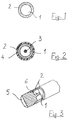
- the first exemplary embodiment of the electrical cable shown in FIG. 1 comprises an alkali metal conductor 1, in particular a sodium conductor, of approximately circular cross section and a jacket 2 above it.
- the jacket 2 is a tube made of a fiber laminate with a polymer matrix.
- the fiber laminate is, for example, a carbon fiber laminate with a fiber content of about 60% by volume.
- the tube can be produced in a pultrusion process with a crosslinked or an uncrosslinked polymer matrix.
- Suitable polymer matrix systems are, for example, the systems LY 556 (synthetic resin), HY 917 (hardener), DY 070 (accelerator) or XB 5132 (synthetic resin), XB 5133 (hardener), DY 070 (accelerator) from the applicant, which are contained in an advertising brochure "® Araldite Matrix Systems ", publ. 38150 / e (910.804 / 20), August 1991.
- the jacket 2 fulfills two functions at the same time: on the one hand, it shields the sodium conductor from the environment, in particular against air and moisture, on the other hand, it represents a non-metallic reinforcement structure and gives the cable the required strength.
- the electrical "composite" cable designed in this way is particularly light.
- the electrical cable can be used particularly well as an energy transmission cable in overhead lines. Due to the low weight and high tensile strength, the cable has a low sag; this means that a smaller number of masts can be used on a given route without falling below the prescribed minimum height of the cable above the ground
- the second exemplary embodiment of the electrical conductor according to the invention shown in FIG. 2 in turn comprises an alkali metal conductor 1, in particular a sodium conductor, of approximately circular cross section and a jacket 2.
- the jacket 2 is in this case a metallic tube, for example made of an aluminum or Copper alloy.
- the sheath 2 shields the conductor 1 against the environment air and moisture-proof.
- a carbon fiber bundle 3 is arranged approximately in the middle of the atrium conductor 1 and has a diameter corresponding to the desired tensile strength of the cable, for example from approximately 1 mm to approximately 20 mm.
- the carbon fibers for example, have a density of 1.82 g / cm3. Their stress at break is, for example, 7 GPa, the elastic modulus 294 GPa.
- the elongation at break in the longitudinal direction of the carbon fiber bundles used, for example, is 2.4%.
- the carbon fiber bundle 3 running approximately in the center of the sodium conductor 1 represents the reinforcement structure for the electrical cable.
- the carbon fiber bundle 3 is fixed approximately centrally in the metallic tube forming the jacket 2.
- the tube is then filled with sodium 1 and sealed airtight and moisture-proof.
- the electrical cable produced in this way is very light, but it has very good mechanical properties and a small electrical resistance.
- the central carbon fiber bundle gives the cable high strength, which is why it hardly sags under tension. Therefore, this variant of the electrical cable is also very suitable for use with overhead lines and allows a reduction in the number of masts required.
- the jacket 2 gives the cable an increased strength against pressure or impact stress. Therefore, the electrical cable designed according to FIG. 2 is not only suitable for use in overhead lines, but it can also be used as an energy transmission cable for underground lines. In this case, the jacket 2 is additionally surrounded by an electrically insulating protective cover 4 (FIG. 2).
- FIG. 3 shows one end of the electrical cable according to FIG. 1.
- the cable end is sealed airtight and moisture-tight with a metallic end piece 5.
- the end piece preferably consists of an aluminum or copper alloy.
- the reinforcing fibers of the sheath 2 are anchored in the end piece 5, for example by gluing and screwing.
- a conical tip 6 protrudes into the alkali metal and ensures perfect electrical contact between the conductor 1 and the metallic end piece 5.
- the metallic end pieces 5 shield the sodium conductor 1 against the ingress of air or Moisture. But they also serve as connection contacts when connecting several cables.
- the variant of an airtight and moisture-tight termination of the cable end shown in FIG. 3 can be seen as an example. For those skilled in the art, further knowledge will result from knowledge of the preceding teaching Exemplary embodiments for such a conclusion.
- the two electrical cables described can be manufactured in various thicknesses depending on the power required.
- the cables according to the invention are significantly lighter than the known copper or aluminum cables, but like these they are also suitable for the transmission of very large currents with overhead lines or with earth lines.
- the table below compares the most important properties of the electrical cables according to the invention with those of the known aluminum or copper cables.
- the embodiment according to FIG. 1 is designated Na / CFRP (sodium / carbon fiber reinforced polymer) and the second embodiment according to FIG. 2 with C / Na / Al (carbon / sodium / aluminum), which indicates the successive layers of the composite Cable describes.
- Cu stands for a copper cable while Al means an aluminum cable.
- the electrical cables according to the invention have a lower weight and a higher tensile strength with the same electrical resistance.
- the thermal expansion of the electrical cables is negligible. This means that the distance between the pylons of an overhead line can be increased without the cables sagging more and less than the prescribed minimum distance from the ground. Because of the smaller number of masts and because of the lighter cable, the construction, assembly and maintenance of the power transmission line are simplified.
- the electrical cables according to the invention can be used both as transmission cables in overhead lines and in earth lines.
Landscapes
- Insulated Conductors (AREA)
- Non-Insulated Conductors (AREA)
Priority Applications (1)
| Application Number | Priority Date | Filing Date | Title |
|---|---|---|---|
| EP93810771A EP0652571A1 (fr) | 1993-11-09 | 1993-11-09 | Câble électrique |
Applications Claiming Priority (1)
| Application Number | Priority Date | Filing Date | Title |
|---|---|---|---|
| EP93810771A EP0652571A1 (fr) | 1993-11-09 | 1993-11-09 | Câble électrique |
Publications (1)
| Publication Number | Publication Date |
|---|---|
| EP0652571A1 true EP0652571A1 (fr) | 1995-05-10 |
Family
ID=8215060
Family Applications (1)
| Application Number | Title | Priority Date | Filing Date |
|---|---|---|---|
| EP93810771A Withdrawn EP0652571A1 (fr) | 1993-11-09 | 1993-11-09 | Câble électrique |
Country Status (1)
| Country | Link |
|---|---|
| EP (1) | EP0652571A1 (fr) |
Citations (3)
| Publication number | Priority date | Publication date | Assignee | Title |
|---|---|---|---|---|
| FR1459666A (fr) * | 1964-12-15 | 1966-11-18 | Simplex Wire & Cable Co | Procédé de fabrication de conducteurs électriques gainés et conducteurs obtenus par ce procédé ou procédé similaire |
| FR1523905A (fr) * | 1966-07-07 | 1968-05-03 | Gen Cable Corp | Conducteur électrique composite à âme en sodium |
| FR1549896A (fr) * | 1967-01-17 | 1968-12-13 |
-
1993
- 1993-11-09 EP EP93810771A patent/EP0652571A1/fr not_active Withdrawn
Patent Citations (3)
| Publication number | Priority date | Publication date | Assignee | Title |
|---|---|---|---|---|
| FR1459666A (fr) * | 1964-12-15 | 1966-11-18 | Simplex Wire & Cable Co | Procédé de fabrication de conducteurs électriques gainés et conducteurs obtenus par ce procédé ou procédé similaire |
| FR1523905A (fr) * | 1966-07-07 | 1968-05-03 | Gen Cable Corp | Conducteur électrique composite à âme en sodium |
| FR1549896A (fr) * | 1967-01-17 | 1968-12-13 |
Similar Documents
| Publication | Publication Date | Title |
|---|---|---|
| DE69923053T2 (de) | Strukturell verstärktes Energie- und/oder Telekomkabel | |
| EP0774157B1 (fr) | Isolateur electrique en caoutchouc de silicone pour applications haute tension | |
| EP0028281B1 (fr) | Pièce isolante synthétique sous tension mécanique, renforcée de fibres de verre sans bore ni composés de bores pour installations électriques à haute tension contenant le gaz hexafluorure de soufre | |
| DE102009031245A1 (de) | Fernübertragungsleitung sowie Halteisolator | |
| DE2934684C2 (de) | Phasen- oder Erdseil | |
| DE3031833A1 (de) | Strangfoermiges verbindungselement aus kunststoff fuer kabel u.ae. | |
| DE3538664C2 (fr) | ||
| DE2512830A1 (de) | Fernsehkamerakabel mit lichtleitfasern | |
| DE3618659A1 (de) | Lichtwellenleiterkabel | |
| EP0652571A1 (fr) | Câble électrique | |
| CH662901A5 (de) | Verfahren zur herstellung eines elektrischen kunststoffisolators und nach dem verfahren hergestellter kunststoffisolator. | |
| DE2742365A1 (de) | Elektrisches kabel mit einer flammwidrigen kunststoffisolierung | |
| EP0456899B1 (fr) | Câble aérien à fibres optiques grande portée | |
| DE3686552T2 (de) | Vorrichtung zur entlastung einer beanspruchung im bereich einer kabelreparatur. | |
| DE69725959T2 (de) | Mastspitze zur Aufhängung von Mittel- und Hochspannungsfreileitungen an Masten | |
| EP1783786B1 (fr) | Système de câble avec un écran magnétique | |
| AT121613B (de) | Hochspannungsisolator, insbesondere für waagrechte Anordnung in Fahrleitungen elektrischer Bahnen. | |
| AT297114B (de) | Isolieranordnung | |
| AT212900B (de) | Befestigung eines Freileitungsseiles an einem Hochspannungsisolator | |
| DE1465922A1 (de) | Kunststoffisolator fuer Hochspannungsuebertragungsleitungen unter Verwendung von Glasfasern und Verfahren zu seiner Herstellung | |
| DE1540034C (de) | Zugfeste Verbindung von teilisoherten Leitern | |
| DE2041814A1 (de) | Bewehrung fuer selbsttragende Fernmeldeluftkabel | |
| DE2845868A1 (de) | Aufschieb-kabelendverschluss | |
| DE2227755A1 (de) | Elektrischer Isolator | |
| EP2299453A2 (fr) | Ligne électrique |
Legal Events
| Date | Code | Title | Description |
|---|---|---|---|
| PUAI | Public reference made under article 153(3) epc to a published international application that has entered the european phase |
Free format text: ORIGINAL CODE: 0009012 |
|
| AK | Designated contracting states |
Kind code of ref document: A1 Designated state(s): CH LI |
|
| STAA | Information on the status of an ep patent application or granted ep patent |
Free format text: STATUS: THE APPLICATION IS DEEMED TO BE WITHDRAWN |
|
| 18D | Application deemed to be withdrawn |
Effective date: 19951111 |