EP0652623B1 - Rotor d'un turbogénérateur avec refroidissement direct à gaz de l'enroulement d'excitation - Google Patents
Rotor d'un turbogénérateur avec refroidissement direct à gaz de l'enroulement d'excitation Download PDFInfo
- Publication number
- EP0652623B1 EP0652623B1 EP94115826A EP94115826A EP0652623B1 EP 0652623 B1 EP0652623 B1 EP 0652623B1 EP 94115826 A EP94115826 A EP 94115826A EP 94115826 A EP94115826 A EP 94115826A EP 0652623 B1 EP0652623 B1 EP 0652623B1
- Authority
- EP
- European Patent Office
- Prior art keywords
- rotor
- insulating strip
- intermediate layer
- corrugated spring
- excitation winding
- Prior art date
- Legal status (The legal status is an assumption and is not a legal conclusion. Google has not performed a legal analysis and makes no representation as to the accuracy of the status listed.)
- Expired - Lifetime
Links
Images


Classifications
-
- H—ELECTRICITY
- H02—GENERATION; CONVERSION OR DISTRIBUTION OF ELECTRIC POWER
- H02K—DYNAMO-ELECTRIC MACHINES
- H02K3/00—Details of windings
- H02K3/04—Windings characterised by the conductor shape, form or construction, e.g. with bar conductors
- H02K3/22—Windings characterised by the conductor shape, form or construction, e.g. with bar conductors consisting of hollow conductors
-
- H—ELECTRICITY
- H02—GENERATION; CONVERSION OR DISTRIBUTION OF ELECTRIC POWER
- H02K—DYNAMO-ELECTRIC MACHINES
- H02K3/00—Details of windings
- H02K3/46—Fastening of windings on the stator or rotor structure
- H02K3/48—Fastening of windings on the stator or rotor structure in slots
-
- H—ELECTRICITY
- H02—GENERATION; CONVERSION OR DISTRIBUTION OF ELECTRIC POWER
- H02K—DYNAMO-ELECTRIC MACHINES
- H02K1/00—Details of the magnetic circuit
- H02K1/06—Details of the magnetic circuit characterised by the shape, form or construction
- H02K1/22—Rotating parts of the magnetic circuit
- H02K1/32—Rotating parts of the magnetic circuit with channels or ducts for flow of cooling medium
Definitions
- the invention relates to a rotor of a turbogenerator with direct gas cooling of the field winding, the field winding conductors being arranged in longitudinal grooves in the rotor barrel of the rotor and these grooves being closed by means of slot wedges, and wherein an insulated tire is provided between the groove base and the field winding conductor lying above it.
- a rotor of this type is known for example from US-A-4,152,610.
- the invention has for its object to provide a rotor of the type mentioned, the excitation winding is secured with simple means against axial relative movements and the securing means used for this neither impair the strength of the rotor nor hinder the flow of the cooling gas.
- this object is achieved in that a spring-elastic intermediate layer in the form of a parallel strip is provided between said insulating strip and said winding conductor, which extends from the end of the bale in the direction of the center of the rotor bale, and in that the spring-elastic intermediate layer has a pair of projections pointing downwards. which engage in lateral recesses in the insulating tire.
- the advantage of the invention can be seen in particular in the fact that simple means can be used to achieve an axial fixation of the spring-elastic intermediate layer, which can withstand all drive loads, can be produced economically and does not impair the cooling gas paths. It can be used for rotors with a wide variety of cooling methods, but is particularly suitable for rotors with a basic groove.
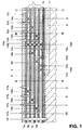
- the excitation winding which is made up of waveguides 1 throughout, is arranged in grooves 2 in the rotor barrel 3.
- the groove 2 is closed by a groove wedge 4.
- a wedge base 5 made of insulating material.
- This wedge pad can itself be resilient. But it can also consist of a strip of insulating material and a separate elastic strip, such as a corrugated spring.
- An insulating strip 6 lies in the groove base. This fills the groove 2 in its entire width and is adapted to the groove shape on its underside. Between the insulating strip 6 and the lowermost waveguide 1d there is a filling strip 7, the function of which will be explained later.
- a corrugated spring 8 takes the place of the filling strip 7.
- the groove 2 has a channel-like depression, a base or sub-groove 9. This is - seen in the circumferential direction - narrower than the groove 2 receiving the waveguide 1. It extends from the rotor bale beginning (not visible in FIG. 1) to about a quarter to a third of the total rotor bale length and runs out there.
- the insulating strips 6, the filling strips 7 and also the corrugated spring 8 are shown in exaggerated thickness in FIGS. 1 to 3.
- a bolt 10 Arranged in the center of the rotor is a bolt 10 made of insulating material and penetrating all waveguides, slot wedges and intermediate layers, which is inserted into the rotor barrel 2 in the inner end. This bolt is used for the axial fixation of the groove assembly.
- the excitation winding is cooled in accordance with the cooling gas flow described at the beginning, identified there by method c).
- a first cooling gas stream 11 arrives from the rotor winding head space (not shown) through lateral slots (likewise not shown) in the waveguides 1a-1d and from there, distributed over a certain axial length, via radially extending first channels 12a, 12b, 12c, 12d , which also pass through the wedge base 5 and the groove wedge 4 to the outside.
- These first radial channels are formed by through holes in the waveguides 1a to 1d. It is the channel 12a is assigned to the waveguide 1a, the channel 12b to the waveguide 1b, the channel 12c to the waveguide 1c and the channel 12d to the waveguide 1d.
- first shut-offs 13a, 13b, 13c and 13d are provided, which are formed by squeezing the waveguides 1a, ..., 1d.
- second shut-offs 14a, 14b, 14c are provided in the waveguides 1a, 1b and 1c behind the radial channel 12. These second shut-offs, together with the shut-off 13d in the waveguide 1d, ensure that the first cooling gas flow emerges from the end section of the rotor and does not mix with the second cooling gas flow 11 ′ to be described below, which is supplied to the central rotor section via the base groove 9 .
- the second cooling gas stream 11 passes from the base groove 9 into second radial channels 15a, 15b, 15c, 15d through bores both in the insulating strip 6, in the filling strip 7 and in the waveguides 1a-1d into the individual waveguides.
- the channel 15a extends to the waveguide 1a, the channel 15b only to the waveguide 1b, the channel 15c to the waveguide 1c and the channel 15d only to the waveguide 1d.
- third shut-offs 16b, 16c, 16d are provided in the waveguides 1b, 1c and 1d in order to avoid the mixing of the individual partial gas flows.
- the partial gas flows in the waveguides 1a to 1d are discharged to the outside near the center of the rotor bale (bolt 10) through third radial channels 17a, 17b, 17c and 17d. These third radial channels are also formed by radially running bores in the waveguides, the wedge base 5 and the slot wedge 4. Fourth shut-offs 18a, 18b, 18c and the bolt 10 ensure an orderly outlet of the cooling gas in the center of the rotor bale.
- FIGS. 3 to 7 now show in detail how the axial fixing of the wave spring 8 takes place in the groove base above the basic groove 9.
- the insulating strip 6 has two lateral recesses 19, the depth of which corresponds approximately to the thickness of the insulating strip 6, near the end of the rotor bale (right edge of the drawing in FIG. 1), symmetrical to its longitudinal axis.
- the corrugated spring 8 is made of spring steel and consists of a corrugated parallel strip, the waves following each other in the strip longitudinal direction.
- the strip has in the area of the recesses 19 in the insulating strip 6 on both sides a downwardly bent tab 20, the bending edge of which is denoted by 21 in FIG. This flap is approximately as wide as the insulating strip is thick, i.e. he does not protrude down the insulating strip 6.
- a thin bandage 22 made of resin-impregnated glass fabric can be wrapped around corrugated spring 8 and insulating strips at the location of recess 19, as indicated by dashed lines in FIG.
- a pad 23 between the corrugated spring 8 and the lowermost waveguide 1d prevents damage to the waveguide insulation 24.
- the insulating strip 6 Due to the shape of the insulating strip 6, which is adapted on its underside to the geometry of the groove base, in combination with the bolt 10, the insulating strip 6 is axially secured.
- the lobes 20 of the corrugated spring 8 engaging in the said recesses 19 in turn secure the axial position of the corrugated spring 8 with respect to the insulating strip 6 and thus also the position of the corrugated spring with respect to the groove and also the excitation winding. It is sufficient to secure this only at the end of the bale. If necessary, more than one pair of recesses 19 and associated tabs 20 can also be provided. These must then be very close to each other, as seen in the longitudinal direction of the groove, so that the corrugated spring 8 can stretch.
- the invention is of course not limited to rotors with an excitation winding made of hollow excitation conductors through which flow essentially in the longitudinal direction and with a cooling scheme according to FIG. It can also be used for rotors without a base groove, that is to say for rotors as are the subject of EP-B-0 173877.
- the spring-elastic intermediate layer can also be other than a corrugated spring.
- an insulating strip 6 is also used there as basic groove insulation.
- the known excitation winding there is no spring-elastic member between the lowermost excitation conductor and the insulating strip, and direct gas cooling is also realized in a different way, but the fixing according to the invention of a corrugated spring 8 on the insulating strip 6 can also be used in such an arrangement, without leaving the scope of the invention.
Landscapes
- Engineering & Computer Science (AREA)
- Power Engineering (AREA)
- Windings For Motors And Generators (AREA)
- Motor Or Generator Cooling System (AREA)
- Insulation, Fastening Of Motor, Generator Windings (AREA)
- Iron Core Of Rotating Electric Machines (AREA)
- Synchronous Machinery (AREA)
Claims (5)
- Rotor d'un turbogénérateur avec refroidissement direct au gaz de l'enroulement d'excitation (1), dans lequel les conducteurs de l'enroulement d'excitation sont disposés dans des encoches longitudinales (2) dans le corps (3) du rotor et ces encoches sont fermées avec des cales d'encoche (4), et dans lequel il est prévu une bande isolante (6) entre le fond de l'encoche et le conducteur (1d) de l'enroulement d'excitation posé sur celui-ci, caractérisé en ce qu'il est prévu, entre ladite bande isolante (6) et ledit conducteur (1d) de l'enroulement d'excitation, une couche intermédiaire (8) de nature élastique sous la forme d'une bande parallèle, de préférence un ressort ondulé, qui s'étend de l'extrémité du corps en direction du milieu du corps du rotor, et en ce que la couche intermédiaire (8) de nature élastique présente une paire de saillies (20) pointant vers le bas, qui s'engagent dans des découpes latérales (19) dans la bande isolante (6).
- Rotor suivant la revendication 1, caractérisé en ce que les saillies (20) sont formées par pliage d'une partie de bord courte par comparaison avec la longueur totale de la couche intermédiaire de nature élastique.
- Rotor suivant la revendication 1 ou 2, caractérisé en ce que la hauteur radiale de la saillie (20) pointant vers le bas correspond environ à l'épaisseur de la bande isolante (6).
- Rotor suivant l'une quelconque des revendications 1 à 3, caractérisé en ce que, dans un rotor avec une encoche de fond (9), la largeur de la bande isolante (6) dans la région de la découpe (19) correspond environ à la largeur du fond de l'encoche de fond (9).
- Rotor suivant l'une quelconque des revendications 1 à 4, caractérisé en ce que, dans la région de la découpe (19), il est prévu un bandage (22), qui est enroulé autour de la bande isolante (6) et de la couche intermédiaire (8) de nature élastique.
Applications Claiming Priority (2)
| Application Number | Priority Date | Filing Date | Title |
|---|---|---|---|
| DE4337628 | 1993-11-04 | ||
| DE4337628A DE4337628A1 (de) | 1993-11-04 | 1993-11-04 | Rotor eines Turbogenerators mit direkter Gaskühlung der Erregerwicklung |
Publications (2)
| Publication Number | Publication Date |
|---|---|
| EP0652623A1 EP0652623A1 (fr) | 1995-05-10 |
| EP0652623B1 true EP0652623B1 (fr) | 1997-07-23 |
Family
ID=6501772
Family Applications (1)
| Application Number | Title | Priority Date | Filing Date |
|---|---|---|---|
| EP94115826A Expired - Lifetime EP0652623B1 (fr) | 1993-11-04 | 1994-10-07 | Rotor d'un turbogénérateur avec refroidissement direct à gaz de l'enroulement d'excitation |
Country Status (12)
| Country | Link |
|---|---|
| US (1) | US5477095A (fr) |
| EP (1) | EP0652623B1 (fr) |
| JP (1) | JPH07170683A (fr) |
| KR (1) | KR100319420B1 (fr) |
| CN (1) | CN1052121C (fr) |
| AT (1) | ATE155940T1 (fr) |
| CZ (1) | CZ284214B6 (fr) |
| DE (2) | DE4337628A1 (fr) |
| ES (1) | ES2107723T3 (fr) |
| HU (1) | HUT71149A (fr) |
| RU (1) | RU2144252C1 (fr) |
| UA (1) | UA34455C2 (fr) |
Families Citing this family (18)
| Publication number | Priority date | Publication date | Assignee | Title |
|---|---|---|---|---|
| DE19621058A1 (de) * | 1996-05-24 | 1997-11-27 | Siemens Ag | Wicklung mit direkter Kühlung |
| DE19829578A1 (de) * | 1998-07-02 | 2000-01-05 | Abb Research Ltd | Elastisches Isolierstoffelement für die Verkeilung einer Wicklung, insbesondere der Statorwicklung einer elektrischen Maschine |
| DE10119593A1 (de) * | 2001-04-21 | 2002-10-24 | Alstom Switzerland Ltd | Rotor eines Turbogenerators |
| RU2237336C2 (ru) * | 2002-12-06 | 2004-09-27 | Открытое акционерное общество "Силовые машины - ЗТЛ, ЛМЗ, Электросила, Энергомашэкспорт" | Устройство для крепления обмотки в пазах сердечника электрической машины |
| GB2399231A (en) * | 2003-03-07 | 2004-09-08 | Alstom | Multi-path cooling of a turbo-generator rotor winding |
| US7049725B2 (en) | 2003-11-24 | 2006-05-23 | Tm4 Inc. | Dynamoelectric machine stator and method for mounting prewound coils thereunto |
| CN101405926B (zh) * | 2006-02-17 | 2012-01-25 | 安萨尔多能源公司 | 用于产生电力的高功率涡轮发电机的通风转子 |
| CN101689779A (zh) | 2007-07-02 | 2010-03-31 | 阿尔斯托姆科技有限公司 | 用于发电机的转子 |
| JP2010104202A (ja) * | 2008-10-27 | 2010-05-06 | Toshiba Corp | 回転電機の回転子 |
| US9246373B2 (en) | 2012-10-31 | 2016-01-26 | General Electric Company | Cooling assembly for electrical machines and methods of assembling the same |
| EP2768120A1 (fr) * | 2013-02-15 | 2014-08-20 | Alstom Technology Ltd | Rotor de générateur électrique |
| US9548640B2 (en) * | 2013-12-05 | 2017-01-17 | General Electric Company | Rotor with cooling manifolds |
| FR3020521B1 (fr) * | 2014-04-29 | 2016-06-03 | Nicolas Langlard | Stator de machine electrique tournante muni d'un bobinage optimise |
| US10326335B2 (en) * | 2016-10-20 | 2019-06-18 | General Electric Technology Gmbh | Radial counter flow jet cooling system |
| CN207625388U (zh) * | 2017-12-24 | 2018-07-17 | 苏州阿福机器人有限公司 | 电机散热结构 |
| RU2691644C1 (ru) * | 2018-11-06 | 2019-06-17 | Публичное акционерное общество "Силовые машины - ЗТЛ, ЛМЗ, Электросила, Энергомашэкспорт" (ПАО "Силовые машины") | Ротор электрической машины |
| JP7305586B2 (ja) | 2020-03-17 | 2023-07-10 | 株式会社東芝 | 回転電機の回転子 |
| CN111835113A (zh) * | 2020-07-07 | 2020-10-27 | 山东齐鲁电机制造有限公司 | 一种适用于变频启动的重型燃气轮发电机转子线圈结构 |
Family Cites Families (21)
| Publication number | Priority date | Publication date | Assignee | Title |
|---|---|---|---|---|
| DE439811C (de) * | 1923-11-05 | 1927-01-18 | Otis Aufzugswerke G M B H | Anordnung zum Befestigen der Wicklung in Nuten elektrischer Maschinen |
| FR585283A (fr) * | 1923-11-05 | 1925-02-24 | Otis Pifre Ateliers Sa | Dispositifs de montage pour conducteurs dans les machines électriques |
| US1555065A (en) * | 1923-11-05 | 1925-09-29 | Otis Elevator Co | Mounting for conductors in electrical machinery and method of applying same |
| DE964161C (de) * | 1952-05-22 | 1957-05-16 | Siemens Ag | Elektrische Maschine mit axialer Nutenbelueftung |
| US3119033A (en) * | 1961-11-07 | 1964-01-21 | Parsons C A & Co Ltd | Dynamo-electric machines |
| US3444407A (en) * | 1966-07-20 | 1969-05-13 | Gen Electric | Rigid conductor bars in dynamoelectric machine slots |
| SU382199A1 (ru) * | 1971-02-03 | 1973-05-22 | Центральное Конструкторское Бюро Главэнергоремонта | Ротор синхронной электрической л\ашины |
| GB1430756A (en) * | 1972-07-11 | 1976-04-07 | Reyrolle Parsons Ltd | Dynamo-electric machines |
| US4152610A (en) * | 1973-08-22 | 1979-05-01 | Patentbureau Danubia | Turbogenerator having dual cooling |
| JPS538708A (en) * | 1976-07-13 | 1978-01-26 | Toshiba Corp | Cage rotor |
| DE2633278C3 (de) * | 1976-07-23 | 1979-04-12 | Kraftwerk Union Ag, 4330 Muelheim | Anordnung zum Verspannen einer im Luftspalt eines Synchrongenerators angeordneten Ständerwicklung |
| DE2742521A1 (de) * | 1977-09-21 | 1979-03-29 | Kraftwerk Union Ag | Anordnung zur radialen verspannung von wicklungen in laeufern elektrischer maschinen |
| JPS59216448A (ja) * | 1983-05-20 | 1984-12-06 | Toshiba Corp | 回転界磁巻線の固定方法 |
| BR8503683A (pt) * | 1984-08-27 | 1986-05-06 | Bbc Brown Boveri & Cie | Rotor de uma maquina eletrica |
| US4633116A (en) * | 1985-10-31 | 1986-12-30 | General Electric Company | Sub-slot cover for dynamoelectric machine |
| SU1427493A1 (ru) * | 1987-03-03 | 1988-09-30 | Ташкентский институт инженеров железнодорожного транспорта | Электрическа машина |
| SU1470145A1 (ru) * | 1987-05-14 | 1990-09-23 | Ленинградское Производственное Электромашиностроительное Объединение "Электросила" Им.С.М.Кирова | Ротор электрической машины |
| SU1552297A1 (ru) * | 1988-06-06 | 1990-03-23 | Научно-Исследовательский, Проектно-Конструкторский И Технологический Институт Завода "Сибэлектротяжмаш" | Короткозамкнутый ротор асинхронного двигател |
| SU1640781A1 (ru) * | 1988-10-04 | 1991-04-07 | Всесоюзный Научно-Исследовательский Институт Электромашиностроения | Стержнева обмотка статора электрической машины |
| DE4218927A1 (de) * | 1992-06-10 | 1993-12-16 | Asea Brown Boveri | Hochspannungsisolation für Statorwicklungen elektrischer Maschinen |
| GB201108802D0 (en) * | 2011-05-25 | 2011-07-06 | Benmore Ventures Ltd | Modular lighting systems |
-
1993
- 1993-11-04 DE DE4337628A patent/DE4337628A1/de not_active Withdrawn
-
1994
- 1994-10-07 EP EP94115826A patent/EP0652623B1/fr not_active Expired - Lifetime
- 1994-10-07 AT AT94115826T patent/ATE155940T1/de not_active IP Right Cessation
- 1994-10-07 DE DE59403450T patent/DE59403450D1/de not_active Expired - Lifetime
- 1994-10-07 ES ES94115826T patent/ES2107723T3/es not_active Expired - Lifetime
- 1994-10-13 CZ CZ942531A patent/CZ284214B6/cs not_active IP Right Cessation
- 1994-10-31 UA UA94105976A patent/UA34455C2/uk unknown
- 1994-11-01 JP JP6268710A patent/JPH07170683A/ja not_active Ceased
- 1994-11-03 HU HU9403158A patent/HUT71149A/hu unknown
- 1994-11-03 RU RU94041732A patent/RU2144252C1/ru active
- 1994-11-03 KR KR1019940028797A patent/KR100319420B1/ko not_active Expired - Fee Related
- 1994-11-04 CN CN94118203A patent/CN1052121C/zh not_active Expired - Lifetime
- 1994-11-04 US US08/334,226 patent/US5477095A/en not_active Expired - Lifetime
Also Published As
| Publication number | Publication date |
|---|---|
| CZ284214B6 (cs) | 1998-09-16 |
| JPH07170683A (ja) | 1995-07-04 |
| CZ253194A3 (en) | 1995-05-17 |
| EP0652623A1 (fr) | 1995-05-10 |
| DE59403450D1 (de) | 1997-09-04 |
| CN1108014A (zh) | 1995-09-06 |
| UA34455C2 (uk) | 2001-03-15 |
| RU94041732A (ru) | 1996-12-10 |
| ES2107723T3 (es) | 1997-12-01 |
| KR100319420B1 (ko) | 2002-04-22 |
| US5477095A (en) | 1995-12-19 |
| KR950015908A (ko) | 1995-06-17 |
| HUT71149A (en) | 1995-11-28 |
| DE4337628A1 (de) | 1995-05-11 |
| RU2144252C1 (ru) | 2000-01-10 |
| CN1052121C (zh) | 2000-05-03 |
| ATE155940T1 (de) | 1997-08-15 |
Similar Documents
| Publication | Publication Date | Title |
|---|---|---|
| EP0652623B1 (fr) | Rotor d'un turbogénérateur avec refroidissement direct à gaz de l'enroulement d'excitation | |
| EP2162969A2 (fr) | Rotor pour générateur | |
| EP0778648B1 (fr) | Barre d'enroulement de stator en forme de barre Roebel avec compensation du champ étendu | |
| DE102019205387A1 (de) | Statorwicklung und Stator mit einer solchen Wicklung | |
| DE2905639A1 (de) | Dynamoelektrische maschine | |
| DE102005002364B4 (de) | Drehstrommaschine | |
| DE102021132259A1 (de) | Statorwicklungsanordnung mit mehreren parallelen Pfaden | |
| WO2015117822A2 (fr) | Élément principal d'un moteur électrique | |
| DE2542033A1 (de) | Kurzschlussringe fuer dynamoelektrische maschine | |
| EP0026499A1 (fr) | Rotor d'une machine électrique | |
| DE102021103722A1 (de) | Stator eines bürstenlosen Elektromotors | |
| DE2218266A1 (de) | Elektrische Maschine | |
| DE102013223727B4 (de) | Elektromotor mit einem segmentierten Stator | |
| EP0805541A1 (fr) | Tête de bobine refroidie par un gaz pour une machine électrique | |
| WO2021219368A1 (fr) | Stator pour machine électrique et machine électrique dotée de stator | |
| AT525718A1 (de) | Rotor | |
| DE8224874U1 (de) | Spannungsausgleichsschlitze | |
| DE2814745C2 (de) | Stromverdrängungsläufer | |
| DE102006010864A1 (de) | Statorwicklungsstab | |
| DE4021861A1 (de) | Gasgekuehlter laeufer einer elektromaschine mit erhoehter variabilitaet der kuehlwege durch multifunktionsleiter | |
| DE3533748C2 (fr) | ||
| DE102007000661A1 (de) | Elektrische Maschine, insbesondere Drehstrom-Asynchron-Hydrogenerator | |
| DE19608289C2 (de) | Aus Scheibenspulen bestehende Hochspannungswicklung für Transformatoren und Drosselspulen | |
| DE1174421B (de) | Wicklungsanordnung fuer Leistungs-transformatoren hoher Spannung | |
| DE102023203099A1 (de) | Kompakte Hairpin-Wicklung |
Legal Events
| Date | Code | Title | Description |
|---|---|---|---|
| PUAI | Public reference made under article 153(3) epc to a published international application that has entered the european phase |
Free format text: ORIGINAL CODE: 0009012 |
|
| AK | Designated contracting states |
Kind code of ref document: A1 Designated state(s): AT CH DE ES FR GB IT LI |
|
| 17P | Request for examination filed |
Effective date: 19951018 |
|
| GRAG | Despatch of communication of intention to grant |
Free format text: ORIGINAL CODE: EPIDOS AGRA |
|
| RAP1 | Party data changed (applicant data changed or rights of an application transferred) |
Owner name: ASEA BROWN BOVERI AG |
|
| 17Q | First examination report despatched |
Effective date: 19961202 |
|
| GRAH | Despatch of communication of intention to grant a patent |
Free format text: ORIGINAL CODE: EPIDOS IGRA |
|
| GRAH | Despatch of communication of intention to grant a patent |
Free format text: ORIGINAL CODE: EPIDOS IGRA |
|
| GRAA | (expected) grant |
Free format text: ORIGINAL CODE: 0009210 |
|
| AK | Designated contracting states |
Kind code of ref document: B1 Designated state(s): AT CH DE ES FR GB IT LI |
|
| REF | Corresponds to: |
Ref document number: 155940 Country of ref document: AT Date of ref document: 19970815 Kind code of ref document: T |
|
| REG | Reference to a national code |
Ref country code: CH Ref legal event code: EP |
|
| REF | Corresponds to: |
Ref document number: 59403450 Country of ref document: DE Date of ref document: 19970904 |
|
| GBT | Gb: translation of ep patent filed (gb section 77(6)(a)/1977) |
Effective date: 19970924 |
|
| ITF | It: translation for a ep patent filed | ||
| ET | Fr: translation filed | ||
| PGFP | Annual fee paid to national office [announced via postgrant information from national office to epo] |
Ref country code: ES Payment date: 19971021 Year of fee payment: 4 |
|
| PG25 | Lapsed in a contracting state [announced via postgrant information from national office to epo] |
Ref country code: LI Free format text: LAPSE BECAUSE OF NON-PAYMENT OF DUE FEES Effective date: 19971031 Ref country code: CH Free format text: LAPSE BECAUSE OF NON-PAYMENT OF DUE FEES Effective date: 19971031 |
|
| REG | Reference to a national code |
Ref country code: ES Ref legal event code: FG2A Ref document number: 2107723 Country of ref document: ES Kind code of ref document: T3 |
|
| PLBE | No opposition filed within time limit |
Free format text: ORIGINAL CODE: 0009261 |
|
| STAA | Information on the status of an ep patent application or granted ep patent |
Free format text: STATUS: NO OPPOSITION FILED WITHIN TIME LIMIT |
|
| REG | Reference to a national code |
Ref country code: CH Ref legal event code: PL |
|
| 26N | No opposition filed | ||
| PG25 | Lapsed in a contracting state [announced via postgrant information from national office to epo] |
Ref country code: ES Free format text: LAPSE BECAUSE OF NON-PAYMENT OF DUE FEES Effective date: 19981008 |
|
| PGFP | Annual fee paid to national office [announced via postgrant information from national office to epo] |
Ref country code: AT Payment date: 20010925 Year of fee payment: 8 |
|
| REG | Reference to a national code |
Ref country code: GB Ref legal event code: IF02 |
|
| PG25 | Lapsed in a contracting state [announced via postgrant information from national office to epo] |
Ref country code: AT Free format text: LAPSE BECAUSE OF NON-PAYMENT OF DUE FEES Effective date: 20021007 |
|
| REG | Reference to a national code |
Ref country code: GB Ref legal event code: 732E |
|
| REG | Reference to a national code |
Ref country code: FR Ref legal event code: CD Ref country code: FR Ref legal event code: CA |
|
| REG | Reference to a national code |
Ref country code: ES Ref legal event code: FD2A Effective date: 19991113 |
|
| REG | Reference to a national code |
Ref country code: FR Ref legal event code: TP |
|
| REG | Reference to a national code |
Ref country code: DE Ref legal event code: R082 Ref document number: 59403450 Country of ref document: DE Representative=s name: ROESLER, UWE, DIPL.-PHYS.UNIV., DE Effective date: 20120621 Ref country code: DE Ref legal event code: R081 Ref document number: 59403450 Country of ref document: DE Owner name: ALSTOM TECHNOLOGY LTD., CH Free format text: FORMER OWNER: ALSTOM, PARIS, FR Effective date: 20120621 |
|
| REG | Reference to a national code |
Ref country code: GB Ref legal event code: 732E Free format text: REGISTERED BETWEEN 20120802 AND 20120808 |
|
| REG | Reference to a national code |
Ref country code: FR Ref legal event code: TP Owner name: ALSTOM TECHNOLOGY LTD., CH Effective date: 20120918 |
|
| PGFP | Annual fee paid to national office [announced via postgrant information from national office to epo] |
Ref country code: GB Payment date: 20130925 Year of fee payment: 20 |
|
| PGFP | Annual fee paid to national office [announced via postgrant information from national office to epo] |
Ref country code: DE Payment date: 20131031 Year of fee payment: 20 Ref country code: FR Payment date: 20130924 Year of fee payment: 20 |
|
| PGFP | Annual fee paid to national office [announced via postgrant information from national office to epo] |
Ref country code: IT Payment date: 20131016 Year of fee payment: 20 |
|
| REG | Reference to a national code |
Ref country code: DE Ref legal event code: R071 Ref document number: 59403450 Country of ref document: DE |
|
| REG | Reference to a national code |
Ref country code: GB Ref legal event code: PE20 Expiry date: 20141006 |
|
| PG25 | Lapsed in a contracting state [announced via postgrant information from national office to epo] |
Ref country code: GB Free format text: LAPSE BECAUSE OF EXPIRATION OF PROTECTION Effective date: 20141006 |