EP0652687A2 - Verfahren und Vorrichtung zum Aufwickelen eines Heizdrahtes - Google Patents
Verfahren und Vorrichtung zum Aufwickelen eines Heizdrahtes Download PDFInfo
- Publication number
- EP0652687A2 EP0652687A2 EP94116840A EP94116840A EP0652687A2 EP 0652687 A2 EP0652687 A2 EP 0652687A2 EP 94116840 A EP94116840 A EP 94116840A EP 94116840 A EP94116840 A EP 94116840A EP 0652687 A2 EP0652687 A2 EP 0652687A2
- Authority
- EP
- European Patent Office
- Prior art keywords
- heating wire
- core
- wound
- terminal pin
- melt
- Prior art date
- Legal status (The legal status is an assumption and is not a legal conclusion. Google has not performed a legal analysis and makes no representation as to the accuracy of the status listed.)
- Granted
Links
Images


Classifications
-
- H—ELECTRICITY
- H01—ELECTRIC ELEMENTS
- H01B—CABLES; CONDUCTORS; INSULATORS; SELECTION OF MATERIALS FOR THEIR CONDUCTIVE, INSULATING OR DIELECTRIC PROPERTIES
- H01B13/00—Apparatus or processes specially adapted for manufacturing conductors or cables
-
- B—PERFORMING OPERATIONS; TRANSPORTING
- B29—WORKING OF PLASTICS; WORKING OF SUBSTANCES IN A PLASTIC STATE IN GENERAL
- B29D—PRODUCING PARTICULAR ARTICLES FROM PLASTICS OR FROM SUBSTANCES IN A PLASTIC STATE
- B29D23/00—Producing tubular articles
- B29D23/001—Pipes; Pipe joints
- B29D23/003—Pipe joints, e.g. straight joints
- B29D23/005—Pipe joints, e.g. straight joints provided with electrical wiring
-
- B—PERFORMING OPERATIONS; TRANSPORTING
- B29—WORKING OF PLASTICS; WORKING OF SUBSTANCES IN A PLASTIC STATE IN GENERAL
- B29C—SHAPING OR JOINING OF PLASTICS; SHAPING OF MATERIAL IN A PLASTIC STATE, NOT OTHERWISE PROVIDED FOR; AFTER-TREATMENT OF THE SHAPED PRODUCTS, e.g. REPAIRING
- B29C65/00—Joining or sealing of preformed parts, e.g. welding of plastics materials; Apparatus therefor
- B29C65/02—Joining or sealing of preformed parts, e.g. welding of plastics materials; Apparatus therefor by heating, with or without pressure
- B29C65/34—Joining or sealing of preformed parts, e.g. welding of plastics materials; Apparatus therefor by heating, with or without pressure using heated elements which remain in the joint, e.g. "verlorenes Schweisselement"
- B29C65/3404—Joining or sealing of preformed parts, e.g. welding of plastics materials; Apparatus therefor by heating, with or without pressure using heated elements which remain in the joint, e.g. "verlorenes Schweisselement" characterised by the type of heated elements which remain in the joint
- B29C65/342—Joining or sealing of preformed parts, e.g. welding of plastics materials; Apparatus therefor by heating, with or without pressure using heated elements which remain in the joint, e.g. "verlorenes Schweisselement" characterised by the type of heated elements which remain in the joint comprising at least a single wire, e.g. in the form of a winding
-
- B—PERFORMING OPERATIONS; TRANSPORTING
- B29—WORKING OF PLASTICS; WORKING OF SUBSTANCES IN A PLASTIC STATE IN GENERAL
- B29C—SHAPING OR JOINING OF PLASTICS; SHAPING OF MATERIAL IN A PLASTIC STATE, NOT OTHERWISE PROVIDED FOR; AFTER-TREATMENT OF THE SHAPED PRODUCTS, e.g. REPAIRING
- B29C65/00—Joining or sealing of preformed parts, e.g. welding of plastics materials; Apparatus therefor
- B29C65/02—Joining or sealing of preformed parts, e.g. welding of plastics materials; Apparatus therefor by heating, with or without pressure
- B29C65/34—Joining or sealing of preformed parts, e.g. welding of plastics materials; Apparatus therefor by heating, with or without pressure using heated elements which remain in the joint, e.g. "verlorenes Schweisselement"
- B29C65/3468—Joining or sealing of preformed parts, e.g. welding of plastics materials; Apparatus therefor by heating, with or without pressure using heated elements which remain in the joint, e.g. "verlorenes Schweisselement" characterised by the means for supplying heat to said heated elements which remain in the join, e.g. special electrical connectors of windings
-
- B—PERFORMING OPERATIONS; TRANSPORTING
- B29—WORKING OF PLASTICS; WORKING OF SUBSTANCES IN A PLASTIC STATE IN GENERAL
- B29C—SHAPING OR JOINING OF PLASTICS; SHAPING OF MATERIAL IN A PLASTIC STATE, NOT OTHERWISE PROVIDED FOR; AFTER-TREATMENT OF THE SHAPED PRODUCTS, e.g. REPAIRING
- B29C65/00—Joining or sealing of preformed parts, e.g. welding of plastics materials; Apparatus therefor
- B29C65/02—Joining or sealing of preformed parts, e.g. welding of plastics materials; Apparatus therefor by heating, with or without pressure
- B29C65/34—Joining or sealing of preformed parts, e.g. welding of plastics materials; Apparatus therefor by heating, with or without pressure using heated elements which remain in the joint, e.g. "verlorenes Schweisselement"
- B29C65/3472—Joining or sealing of preformed parts, e.g. welding of plastics materials; Apparatus therefor by heating, with or without pressure using heated elements which remain in the joint, e.g. "verlorenes Schweisselement" characterised by the composition of the heated elements which remain in the joint
- B29C65/3476—Joining or sealing of preformed parts, e.g. welding of plastics materials; Apparatus therefor by heating, with or without pressure using heated elements which remain in the joint, e.g. "verlorenes Schweisselement" characterised by the composition of the heated elements which remain in the joint being metallic
- B29C65/348—Joining or sealing of preformed parts, e.g. welding of plastics materials; Apparatus therefor by heating, with or without pressure using heated elements which remain in the joint, e.g. "verlorenes Schweisselement" characterised by the composition of the heated elements which remain in the joint being metallic with a polymer coating
-
- B—PERFORMING OPERATIONS; TRANSPORTING
- B29—WORKING OF PLASTICS; WORKING OF SUBSTANCES IN A PLASTIC STATE IN GENERAL
- B29C—SHAPING OR JOINING OF PLASTICS; SHAPING OF MATERIAL IN A PLASTIC STATE, NOT OTHERWISE PROVIDED FOR; AFTER-TREATMENT OF THE SHAPED PRODUCTS, e.g. REPAIRING
- B29C66/00—General aspects of processes or apparatus for joining preformed parts
- B29C66/50—General aspects of joining tubular articles; General aspects of joining long products, i.e. bars or profiled elements; General aspects of joining single elements to tubular articles, hollow articles or bars; General aspects of joining several hollow-preforms to form hollow or tubular articles
- B29C66/51—Joining tubular articles, profiled elements or bars; Joining single elements to tubular articles, hollow articles or bars; Joining several hollow-preforms to form hollow or tubular articles
- B29C66/52—Joining tubular articles, bars or profiled elements
- B29C66/522—Joining tubular articles
- B29C66/5221—Joining tubular articles for forming coaxial connections, i.e. the tubular articles to be joined forming a zero angle relative to each other
-
- B—PERFORMING OPERATIONS; TRANSPORTING
- B29—WORKING OF PLASTICS; WORKING OF SUBSTANCES IN A PLASTIC STATE IN GENERAL
- B29C—SHAPING OR JOINING OF PLASTICS; SHAPING OF MATERIAL IN A PLASTIC STATE, NOT OTHERWISE PROVIDED FOR; AFTER-TREATMENT OF THE SHAPED PRODUCTS, e.g. REPAIRING
- B29C66/00—General aspects of processes or apparatus for joining preformed parts
- B29C66/50—General aspects of joining tubular articles; General aspects of joining long products, i.e. bars or profiled elements; General aspects of joining single elements to tubular articles, hollow articles or bars; General aspects of joining several hollow-preforms to form hollow or tubular articles
- B29C66/51—Joining tubular articles, profiled elements or bars; Joining single elements to tubular articles, hollow articles or bars; Joining several hollow-preforms to form hollow or tubular articles
- B29C66/52—Joining tubular articles, bars or profiled elements
- B29C66/522—Joining tubular articles
- B29C66/5229—Joining tubular articles involving the use of a socket
- B29C66/52291—Joining tubular articles involving the use of a socket said socket comprising a stop
- B29C66/52292—Joining tubular articles involving the use of a socket said socket comprising a stop said stop being internal
-
- H—ELECTRICITY
- H05—ELECTRIC TECHNIQUES NOT OTHERWISE PROVIDED FOR
- H05B—ELECTRIC HEATING; ELECTRIC LIGHT SOURCES NOT OTHERWISE PROVIDED FOR; CIRCUIT ARRANGEMENTS FOR ELECTRIC LIGHT SOURCES, IN GENERAL
- H05B3/00—Ohmic-resistance heating
- H05B3/40—Heating elements having the shape of rods or tubes
- H05B3/42—Heating elements having the shape of rods or tubes non-flexible
- H05B3/48—Heating elements having the shape of rods or tubes non-flexible heating conductor embedded in insulating material
-
- B—PERFORMING OPERATIONS; TRANSPORTING
- B29—WORKING OF PLASTICS; WORKING OF SUBSTANCES IN A PLASTIC STATE IN GENERAL
- B29C—SHAPING OR JOINING OF PLASTICS; SHAPING OF MATERIAL IN A PLASTIC STATE, NOT OTHERWISE PROVIDED FOR; AFTER-TREATMENT OF THE SHAPED PRODUCTS, e.g. REPAIRING
- B29C66/00—General aspects of processes or apparatus for joining preformed parts
- B29C66/70—General aspects of processes or apparatus for joining preformed parts characterised by the composition, physical properties or the structure of the material of the parts to be joined; Joining with non-plastics material
- B29C66/71—General aspects of processes or apparatus for joining preformed parts characterised by the composition, physical properties or the structure of the material of the parts to be joined; Joining with non-plastics material characterised by the composition of the plastics material of the parts to be joined
-
- Y—GENERAL TAGGING OF NEW TECHNOLOGICAL DEVELOPMENTS; GENERAL TAGGING OF CROSS-SECTIONAL TECHNOLOGIES SPANNING OVER SEVERAL SECTIONS OF THE IPC; TECHNICAL SUBJECTS COVERED BY FORMER USPC CROSS-REFERENCE ART COLLECTIONS [XRACs] AND DIGESTS
- Y10—TECHNICAL SUBJECTS COVERED BY FORMER USPC
- Y10T—TECHNICAL SUBJECTS COVERED BY FORMER US CLASSIFICATION
- Y10T29/00—Metal working
- Y10T29/49—Method of mechanical manufacture
- Y10T29/49002—Electrical device making
- Y10T29/49082—Resistor making
- Y10T29/49083—Heater type
-
- Y—GENERAL TAGGING OF NEW TECHNOLOGICAL DEVELOPMENTS; GENERAL TAGGING OF CROSS-SECTIONAL TECHNOLOGIES SPANNING OVER SEVERAL SECTIONS OF THE IPC; TECHNICAL SUBJECTS COVERED BY FORMER USPC CROSS-REFERENCE ART COLLECTIONS [XRACs] AND DIGESTS
- Y10—TECHNICAL SUBJECTS COVERED BY FORMER USPC
- Y10T—TECHNICAL SUBJECTS COVERED BY FORMER US CLASSIFICATION
- Y10T29/00—Metal working
- Y10T29/49—Method of mechanical manufacture
- Y10T29/49002—Electrical device making
- Y10T29/49082—Resistor making
- Y10T29/49087—Resistor making with envelope or housing
-
- Y—GENERAL TAGGING OF NEW TECHNOLOGICAL DEVELOPMENTS; GENERAL TAGGING OF CROSS-SECTIONAL TECHNOLOGIES SPANNING OVER SEVERAL SECTIONS OF THE IPC; TECHNICAL SUBJECTS COVERED BY FORMER USPC CROSS-REFERENCE ART COLLECTIONS [XRACs] AND DIGESTS
- Y10—TECHNICAL SUBJECTS COVERED BY FORMER USPC
- Y10T—TECHNICAL SUBJECTS COVERED BY FORMER US CLASSIFICATION
- Y10T29/00—Metal working
- Y10T29/49—Method of mechanical manufacture
- Y10T29/49002—Electrical device making
- Y10T29/49082—Resistor making
- Y10T29/49087—Resistor making with envelope or housing
- Y10T29/49096—Resistor making with envelope or housing with winding
-
- Y—GENERAL TAGGING OF NEW TECHNOLOGICAL DEVELOPMENTS; GENERAL TAGGING OF CROSS-SECTIONAL TECHNOLOGIES SPANNING OVER SEVERAL SECTIONS OF THE IPC; TECHNICAL SUBJECTS COVERED BY FORMER USPC CROSS-REFERENCE ART COLLECTIONS [XRACs] AND DIGESTS
- Y10—TECHNICAL SUBJECTS COVERED BY FORMER USPC
- Y10T—TECHNICAL SUBJECTS COVERED BY FORMER US CLASSIFICATION
- Y10T29/00—Metal working
- Y10T29/49—Method of mechanical manufacture
- Y10T29/49002—Electrical device making
- Y10T29/49082—Resistor making
- Y10T29/49087—Resistor making with envelope or housing
- Y10T29/49098—Applying terminal
-
- Y—GENERAL TAGGING OF NEW TECHNOLOGICAL DEVELOPMENTS; GENERAL TAGGING OF CROSS-SECTIONAL TECHNOLOGIES SPANNING OVER SEVERAL SECTIONS OF THE IPC; TECHNICAL SUBJECTS COVERED BY FORMER USPC CROSS-REFERENCE ART COLLECTIONS [XRACs] AND DIGESTS
- Y10—TECHNICAL SUBJECTS COVERED BY FORMER USPC
- Y10T—TECHNICAL SUBJECTS COVERED BY FORMER US CLASSIFICATION
- Y10T29/00—Metal working
- Y10T29/49—Method of mechanical manufacture
- Y10T29/49002—Electrical device making
- Y10T29/49082—Resistor making
- Y10T29/49101—Applying terminal
-
- Y—GENERAL TAGGING OF NEW TECHNOLOGICAL DEVELOPMENTS; GENERAL TAGGING OF CROSS-SECTIONAL TECHNOLOGIES SPANNING OVER SEVERAL SECTIONS OF THE IPC; TECHNICAL SUBJECTS COVERED BY FORMER USPC CROSS-REFERENCE ART COLLECTIONS [XRACs] AND DIGESTS
- Y10—TECHNICAL SUBJECTS COVERED BY FORMER USPC
- Y10T—TECHNICAL SUBJECTS COVERED BY FORMER US CLASSIFICATION
- Y10T29/00—Metal working
- Y10T29/49—Method of mechanical manufacture
- Y10T29/49002—Electrical device making
- Y10T29/49117—Conductor or circuit manufacturing
- Y10T29/49174—Assembling terminal to elongated conductor
- Y10T29/49181—Assembling terminal to elongated conductor by deforming
- Y10T29/49185—Assembling terminal to elongated conductor by deforming of terminal
-
- Y—GENERAL TAGGING OF NEW TECHNOLOGICAL DEVELOPMENTS; GENERAL TAGGING OF CROSS-SECTIONAL TECHNOLOGIES SPANNING OVER SEVERAL SECTIONS OF THE IPC; TECHNICAL SUBJECTS COVERED BY FORMER USPC CROSS-REFERENCE ART COLLECTIONS [XRACs] AND DIGESTS
- Y10—TECHNICAL SUBJECTS COVERED BY FORMER USPC
- Y10T—TECHNICAL SUBJECTS COVERED BY FORMER US CLASSIFICATION
- Y10T29/00—Metal working
- Y10T29/49—Method of mechanical manufacture
- Y10T29/49002—Electrical device making
- Y10T29/49117—Conductor or circuit manufacturing
- Y10T29/49174—Assembling terminal to elongated conductor
- Y10T29/49181—Assembling terminal to elongated conductor by deforming
- Y10T29/49185—Assembling terminal to elongated conductor by deforming of terminal
- Y10T29/49192—Assembling terminal to elongated conductor by deforming of terminal with insulation removal
-
- Y—GENERAL TAGGING OF NEW TECHNOLOGICAL DEVELOPMENTS; GENERAL TAGGING OF CROSS-SECTIONAL TECHNOLOGIES SPANNING OVER SEVERAL SECTIONS OF THE IPC; TECHNICAL SUBJECTS COVERED BY FORMER USPC CROSS-REFERENCE ART COLLECTIONS [XRACs] AND DIGESTS
- Y10—TECHNICAL SUBJECTS COVERED BY FORMER USPC
- Y10T—TECHNICAL SUBJECTS COVERED BY FORMER US CLASSIFICATION
- Y10T29/00—Metal working
- Y10T29/49—Method of mechanical manufacture
- Y10T29/4998—Combined manufacture including applying or shaping of fluent material
- Y10T29/49982—Coating
- Y10T29/49986—Subsequent to metal working
-
- Y—GENERAL TAGGING OF NEW TECHNOLOGICAL DEVELOPMENTS; GENERAL TAGGING OF CROSS-SECTIONAL TECHNOLOGIES SPANNING OVER SEVERAL SECTIONS OF THE IPC; TECHNICAL SUBJECTS COVERED BY FORMER USPC CROSS-REFERENCE ART COLLECTIONS [XRACs] AND DIGESTS
- Y10—TECHNICAL SUBJECTS COVERED BY FORMER USPC
- Y10T—TECHNICAL SUBJECTS COVERED BY FORMER US CLASSIFICATION
- Y10T29/00—Metal working
- Y10T29/51—Plural diverse manufacturing apparatus including means for metal shaping or assembling
- Y10T29/5136—Separate tool stations for selective or successive operation on work
- Y10T29/5137—Separate tool stations for selective or successive operation on work including assembling or disassembling station
- Y10T29/5142—Separate tool stations for selective or successive operation on work including assembling or disassembling station and means to sever work from supply
-
- Y—GENERAL TAGGING OF NEW TECHNOLOGICAL DEVELOPMENTS; GENERAL TAGGING OF CROSS-SECTIONAL TECHNOLOGIES SPANNING OVER SEVERAL SECTIONS OF THE IPC; TECHNICAL SUBJECTS COVERED BY FORMER USPC CROSS-REFERENCE ART COLLECTIONS [XRACs] AND DIGESTS
- Y10—TECHNICAL SUBJECTS COVERED BY FORMER USPC
- Y10T—TECHNICAL SUBJECTS COVERED BY FORMER US CLASSIFICATION
- Y10T29/00—Metal working
- Y10T29/53—Means to assemble or disassemble
- Y10T29/5313—Means to assemble electrical device
- Y10T29/53187—Multiple station assembly apparatus
-
- Y—GENERAL TAGGING OF NEW TECHNOLOGICAL DEVELOPMENTS; GENERAL TAGGING OF CROSS-SECTIONAL TECHNOLOGIES SPANNING OVER SEVERAL SECTIONS OF THE IPC; TECHNICAL SUBJECTS COVERED BY FORMER USPC CROSS-REFERENCE ART COLLECTIONS [XRACs] AND DIGESTS
- Y10—TECHNICAL SUBJECTS COVERED BY FORMER USPC
- Y10T—TECHNICAL SUBJECTS COVERED BY FORMER US CLASSIFICATION
- Y10T29/00—Metal working
- Y10T29/53—Means to assemble or disassemble
- Y10T29/5313—Means to assemble electrical device
- Y10T29/532—Conductor
- Y10T29/53209—Terminal or connector
- Y10T29/53213—Assembled to wire-type conductor
- Y10T29/53235—Means to fasten by deformation
-
- Y—GENERAL TAGGING OF NEW TECHNOLOGICAL DEVELOPMENTS; GENERAL TAGGING OF CROSS-SECTIONAL TECHNOLOGIES SPANNING OVER SEVERAL SECTIONS OF THE IPC; TECHNICAL SUBJECTS COVERED BY FORMER USPC CROSS-REFERENCE ART COLLECTIONS [XRACs] AND DIGESTS
- Y10—TECHNICAL SUBJECTS COVERED BY FORMER USPC
- Y10T—TECHNICAL SUBJECTS COVERED BY FORMER US CLASSIFICATION
- Y10T29/00—Metal working
- Y10T29/53—Means to assemble or disassemble
- Y10T29/5313—Means to assemble electrical device
- Y10T29/53265—Means to assemble electrical device with work-holder for assembly
-
- Y—GENERAL TAGGING OF NEW TECHNOLOGICAL DEVELOPMENTS; GENERAL TAGGING OF CROSS-SECTIONAL TECHNOLOGIES SPANNING OVER SEVERAL SECTIONS OF THE IPC; TECHNICAL SUBJECTS COVERED BY FORMER USPC CROSS-REFERENCE ART COLLECTIONS [XRACs] AND DIGESTS
- Y10—TECHNICAL SUBJECTS COVERED BY FORMER USPC
- Y10T—TECHNICAL SUBJECTS COVERED BY FORMER US CLASSIFICATION
- Y10T29/00—Metal working
- Y10T29/53—Means to assemble or disassemble
- Y10T29/5313—Means to assemble electrical device
- Y10T29/5327—Means to fasten by deforming
Definitions
- the present invention relates to a method of and an apparatus for winding a heating wire on an outer peripheral portion of a core for forming by injection molding an electrically melt-bonding joint in which the heating wire is embedded in the joint.
- a method of making the electrically melt-bonding joint comprises a winding step wherein the heating wire is wound in a coil form by a predetermined number of turns on an outer peripheral portion of a core for forming the inner periphery of the joint, a terminal processing step wherein the heating wire is cut to have a predetermined length, and each end portion of the heating wire is inserted into each terminal pin to thereby electrically connect the terminal pins to the heating wire, and a shaping step wherein the core on which the heating wire is wound in a coil form is set in a metal mold, and molten resin is injected into the metal mold.
- the conventional method had problems in the winding step and the terminal processing step in the manufacture of the electrically melt-bonding joint. Namely, when the terminal pins are electrically connected to the both ends of the heating wire after the heating wire has been wound on an outer peripheral portion of the core, it was necessary to conduct operations for connecting the terminal pins to the heating wire in a limited narrow space near the core. Accordingly, it was difficult to employ automation or a linear arrangement for the winding step and the terminal processing step, and these steps were obliged to rely on manual labor. Further, in a case that after the heating wire has been wound on an outer peripheral portion at an end of the core, the wire has to be wound on an outer peripheral portion at the other side. In this case, the distance of wound portions is spaced as indicated by broken lines in Figure 8. Thus, when the spacing operation and the winding operation for the heating wire are conducted manually, deflection of the position is apt to occur, and a correcting operation by manual labor is needed after the winding operation.
- a method of winding a heating wire coated with an insulation resin on an outer peripheral portion of a core for forming the inner periphery of an electrically melt-bonding joint the method being characterized by comprising the following steps (1) through (4):
- an apparatus for winding a heating wire on a core for forming the inner periphery of an electric melt-bonding joint which comprises a core in a generally cylindrical shape which is capable of rotating around its axial center, the core being relatively moved in the axial direction with respect to a heating wire, an engaging piece mounted on the core, which has a holding portion for holding a heating wire, and a fixing means to fix a terminal pin to the leading end of the heating wire, wherein the engaging piece has a holding portion for holding the terminal pin, whereby the heating wire is wound on an outer peripheral portion of the core by rotating the core.
- an apparatus for winding a heating wire on a core for forming the inner periphery of an electrically melt-bonding joint which comprises a core in a generally cylindrical shape, an engaging piece mounted on the core, which has a holding portion for holding a heating wire, a spacing means for spacing the distance of the heating wire to be wound on the core, a fixing means for fixing a terminal pin to the leading end of the heating wire, means for engaging the heating wire with the spacing means, and means for rotating the core around its center axis and causing relative movement of the same in its axial direction with respect to the heating wire, whereby the heating wire is wound continuously at both sides of the outer periphery of the core.
- reference numeral 1 designates a heating wire such as a nichrome wire, the outer surface of which is coated with an insulation resin such as polyethylene, polybutene or the like.
- the heating wire 1 is wound on a rewinding roller 2 and it is drawn through a transferring device 3.
- Numeral 6 designates a core on which the heating wire 1 is to be wound.
- the core 6 is rotated around its axial center and moved in its axial direction by means of a rotating and driving device 11 and in association with an automatic feeding device 12 for feeding the heating wire from the rewinding roller 2, the rotating and driving device and the automatic feeding device being driven by signals from a controller 10.
- An engaging piece 7a and a wire spacing tool 7b are respectively detachably mounted on an end portion of the core 6.
- Numeral 8 designates an electric heating iron
- numeral 9 designate a pulling device
- a symbol R designates a robot, these elements being driven according to signals from the controller 10.
- the heating wire 1 wound on the rewinding roller 2 is drawn through the transferring device 3 comprising guide rollers 31, a tension roller 32, a nip roller 33 and so on.
- a cutter 34 is disposed at the feeding side of the nip roller 33 so as to cut the heating wire 1 by the aid of a hydraulic device (not shown) or the like.
- the leading end of the heating wire 1 fed through the nip roller 33 is gripped by an arm R1 of the robot R operated in association with the rotating and driving device (not shown), and the heating wire 1 is successively transferred to operational positions for a peeling-off step, a caulking step, a winding step and so on.
- a stripper 4 and a caulking device 5 are disposed near the arm R1 of the robot R.
- the insulation resin covering the leading end portion of the heating wire 1 is peeled off with the stripper 4.
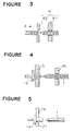
- the stripper 4 comprises each pair of grippers 41 and cutting blades 42.
- the leading end portion of the heating wire 1 is gripped by the pair of grippers 41 and the free end side of the-heating wire is clamped by the cutting blades 42.
- the cutting blades 42 are moved in the direction of X in Figure 3 so that the insulation resin covering the leading end portion of the heating wire 1 is peeled off.
- a terminal pin 1a is connected to the leading end portion of the heating wire 1 which has been subjected to the peeling-off operation of the insulation resin.
- the terminal pin 1a is successively supplied by means of an aligning device such as a parts feeder or the like (not shown).
- an aligning device such as a parts feeder or the like (not shown).
- the leading end portion of the heating wire 1 is inserted, and then, the terminal pin 1a is pressed by the caulking device 5 as shown in Figure 4.
- the terminal pin 1a connected to the leading end portion of the heating wire 1 is fitted to the engaging piece 7a which is mounted on an end of the core 6.
- a notch portion or a recess 71 is formed in an upper surface of the free end of the engaging piece 7a so as to receive the terminal pin 1a.
- the terminal pin 1a is engaged with the notch portion 71.
- the spacing tool 7b is previously disengaged from the one end portion of the core 6.
- the core 6 is rotated around its axial center and at the same time, moved in the axial direction whereby the heating wire 1 is wound on an outer peripheral portion of the core.
- the heating wire 1 In the winding step, it is important to wind the heating wire 1 in a state that the heating wire 1 intersects substantially in perpendicular to the axial center of the core 6.
- the heating wire 1 can be wound in a coil form in contact with the outer peripheral portion of the core 6.
- the rotation of the core 6 is stopped.
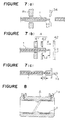
- the electric heating iron 8 is applied to the wound portion of the heating wire 1 to melt the insulation resin covering the outer periphery of the heating wire 1, whereby adjacent portions of the wound heating wire are melt-bonded with molten resin as indicated by a symbol B in Figure 6(a).
- the winding operation to the heating wire 1 is started to an outer peripheral portion at the other end side of the core 6.
- the spacing tool 7b is fitted to an end of the core, as shown in Figure 6(a), and then, the core 6 is moved to a certain extent in the direction of Y in Figure 6(a) so that the heating wire 1 is engaged with the free end portion of the spacing tool 7b. Then, the position of starting the winding of the heating wire 1 is determined, and then, the core is rotated, whereby the heating wire 1 is wound by a predetermined number of turns on the outer peripheral portion of the other end side of the core 6. Then, the rotation of the core 6 is stopped. Thereafter, the electric heating iron 8 is applied to several portions of the heating wire 1 wound in a coil form, whereby adjacent portions of the heating wire are joined with molten resin as shown in Figure 6(b).
- the heating wire is wound by a predetermined number of turns on the outer peripheral portion of the other end side of the core 6 by repeating the winding operations and the melt-bonding operations of the heating wire, and then, the rotation of the core 6 is stopped and an unwound portion of the heating wire 1 is cut with a cutter 34.
- the cut portion, i.e. the rear end portion of the heating wire 1 is treated to peel off the insulation resin covering the rear end portion, and a terminal pin 1a is connected to the rear end portion in the same manner as the before-mentioned operations.
- the length S of the portion of the heating wire 1 where the insulation resin is peeled off can be constant by releasing a pulling force acting on the heating wire 1 and connecting the terminal pin 1a to the rear end portion of the heating wire 1.
- the heating wire 1 gripped by the arm R1 of the robot R is cut with the cutter 34, and then, the gripping force of the arm R1 is released as shown in Figure 7(a). Then, a tensile force acting on the heating wire 1 in the winding step is released, and at the same time, the insulation resin covering the outer periphery of the heating wire 1 is shrinked by a length L1 from the cut end portion.
- the terminal pin 1a is caulked and fixed to the rear end portion.
- the terminal pin 1a connected to the rear end portion of the heating wire 1 is engaged with a pulling device 9.
- the core 6 is rotated while a predetermined tensile force is applied to the rear end side of the heating wire 1 whereby the rear end portion of the heating wire 1 is wound on the outer peripheral portion of the core 6.
- the electric heating iron 8 is applied to the heating wire 1 at a portion near the terminal pin 1a to thereby melt the insulation resin and joint the rear end portion of the heating wire 1 to the adjoining portion of the wire.
- the engaging piece 7a and the spacing tool 7b are removed, and the core 6 is put in a metal mold. Then, molten resin such as polyethylene, polybutene or the like is injected into a cavity formed between the core 6 and the metal mold whereby the electrically melt-bonding joint A as shown in Figure 8 can be obtained.
- molten resin such as polyethylene, polybutene or the like is injected into a cavity formed between the core 6 and the metal mold whereby the electrically melt-bonding joint A as shown in Figure 8 can be obtained.
- the heating wire 1 is wound on an outer peripheral portion of an end side of the core 6; the spacing tool 7b is used to space the heating wire on the core 6, and then, the heating wire 1 is wound on an outer peripheral portion of the other end side of the core 6.
- the spacing operation for the heating wire 1 is unnecessary.
- the core is moved in the axial direction while the heating wire is wound on an outer peripheral portion of the core.
- the same effect can be obtained by winding the heating wire 1 while the heating wire 1 is moved in the axial direction of the core 6.
- the engaging piece 7a and the spacing tool 7b may be mounted on the rotating and driving device if the device is disposed at an end side of the core 6 on which the heating wire 1 is wound.
- the employment of an automation system and energy saving in the winding step and the terminal processing step are possible, and the heating wire can be wound easily and certainly on an outer peripheral portion of a core.
- an electric heating iron is applied to a wound portion of the heating wire to melt insulation resin to thereby melt-bonding adjacent portions of the heating wire. Accordingly, there is no shift of position of the heating wire.
- the heating wire can be tightly wound on the core by engaging a terminal pin fixed to an end portion of the heating wire to apply a tensile force to the heating wire.
- the rotation of the core is stopped; the heating wire is engaged with a spacing tool, and the core is started to rotate. Accordingly, the heating wire is wound on an outer peripheral portion of the other end side of the core without causing a shift of position of the heating wire.
Landscapes
- Engineering & Computer Science (AREA)
- Mechanical Engineering (AREA)
- Manufacturing & Machinery (AREA)
- Branch Pipes, Bends, And The Like (AREA)
- Lining Or Joining Of Plastics Or The Like (AREA)
- Resistance Heating (AREA)
- Wire Processing (AREA)
- Injection Moulding Of Plastics Or The Like (AREA)
Applications Claiming Priority (3)
| Application Number | Priority Date | Filing Date | Title |
|---|---|---|---|
| JP27989093 | 1993-11-09 | ||
| JP279890/93 | 1993-11-09 | ||
| JP5279890A JP2978698B2 (ja) | 1993-11-09 | 1993-11-09 | 電熱線の巻回方法及びその装置 |
Publications (3)
| Publication Number | Publication Date |
|---|---|
| EP0652687A2 true EP0652687A2 (de) | 1995-05-10 |
| EP0652687A3 EP0652687A3 (de) | 1995-12-20 |
| EP0652687B1 EP0652687B1 (de) | 2002-02-20 |
Family
ID=17617360
Family Applications (1)
| Application Number | Title | Priority Date | Filing Date |
|---|---|---|---|
| EP94116840A Expired - Lifetime EP0652687B1 (de) | 1993-11-09 | 1994-10-25 | Verfahren und Vorrichtung zum Aufwickelen eines Heizdrahtes |
Country Status (7)
| Country | Link |
|---|---|
| US (2) | US5581872A (de) |
| EP (1) | EP0652687B1 (de) |
| JP (1) | JP2978698B2 (de) |
| KR (1) | KR100327284B1 (de) |
| DE (1) | DE69429899T2 (de) |
| MY (1) | MY111570A (de) |
| TW (1) | TW259754B (de) |
Cited By (1)
| Publication number | Priority date | Publication date | Assignee | Title |
|---|---|---|---|---|
| CN103474188A (zh) * | 2013-09-30 | 2013-12-25 | 苏州天惠精密机械科技有限公司 | 电子元件缠线机构 |
Families Citing this family (10)
| Publication number | Priority date | Publication date | Assignee | Title |
|---|---|---|---|---|
| US6061902A (en) * | 1998-04-21 | 2000-05-16 | Dalhousie University | Method for recovering leads embedded within a composite structure |
| AU780812B2 (en) * | 1999-09-14 | 2005-04-21 | Georg Fischer Wavin Ag | Improved welding socket |
| JP3529039B2 (ja) | 1999-09-30 | 2004-05-24 | 株式会社ジェイ・エム・エス | 医療用具の嵌合構造およびその製造方法 |
| JP2006329360A (ja) * | 2005-05-27 | 2006-12-07 | Hitachi Metals Ltd | 電気融着継手、その製造方法及び巻線装置 |
| US10250005B2 (en) * | 2014-02-24 | 2019-04-02 | Hubbell Incorporated | Cable installation aid for multi-strand electrical conductors |
| US10139132B2 (en) * | 2015-03-31 | 2018-11-27 | Lam Research Corporation | Apparatus for thermal control of tubing assembly and associated methods |
| DE102018130008A1 (de) * | 2018-11-27 | 2020-05-28 | Rkt Rodinger Kunststoff-Technik Gmbh | Verfahren zum Herstellen eines Kunststoffteils mit mehreren durch das Kunststoffteil verlaufenden Drahtbahnen, Werkzeugeinleger, Wickelvorrichtung und System zum Herstellen eines Kunststoffteils mit mehreren durch das Kunststoffteil verlaufenden Drahtbahnen |
| DE102020126010B4 (de) * | 2020-10-05 | 2025-05-08 | Türk & Hillinger GmbH | Elektrische Heizvorrichtung und Verfahren zur Herstellung einer elektrischen Heizvorrichtung |
| CN112676499B (zh) * | 2020-12-07 | 2022-10-11 | 北京泰杰伟业科技有限公司 | 一种血管支架制造用模具及其加工设备 |
| CN112864753B (zh) * | 2021-01-18 | 2023-12-26 | 舒捷 | 一种用于数据连接线的包装设备 |
Family Cites Families (15)
| Publication number | Priority date | Publication date | Assignee | Title |
|---|---|---|---|---|
| US3378672A (en) * | 1966-03-18 | 1968-04-16 | Susquehanna Corp | Insulated, electrical resistance wire and welding sleeve made therefrom |
| US3506519A (en) * | 1967-01-13 | 1970-04-14 | Susquehanna Corp | Method of making interlocked welded connections between thermoplastic articles |
| US3707756A (en) * | 1971-02-12 | 1973-01-02 | Thomas & Betts Corp | Wire positioner for terminal attaching machine |
| US3940228A (en) * | 1974-08-08 | 1976-02-24 | International Telephone And Telegraph Corporation | Telephone cord mandrel end retainer |
| CH631252A5 (de) * | 1978-05-29 | 1982-07-30 | Werner Sturm | Verfahren und vorrichtung zur herstellung einer elektro-schweissmuffe aus einem thermoplast. |
| GB2090558B (en) * | 1981-01-06 | 1984-08-30 | British Gas Corp | Method of manufacture of a heat sealable fitting and fitting made by such method |
| NL8602469A (nl) * | 1986-09-30 | 1988-04-18 | Wavin Bv | Werkwijze alsmede inrichting en extrusiekop voor het onder toepassen van extrusie vervaardigen van lasbuismoffen en lasfittingen uit thermoplastische materiaal onder toepassing van een in een eerste extruder gevormd eerste buisdeel. |
| JPS63112142A (ja) * | 1986-10-28 | 1988-05-17 | フイリツプス ピトロ−リアム カンパニ− | 熱可塑性構造体を作る方法と装置 |
| GB8719430D0 (en) * | 1987-08-17 | 1987-09-23 | Glynwed Tubes & Fittings | Manufacturing electrofusion coupler |
| GB8910070D0 (en) * | 1989-05-03 | 1989-06-21 | Fusion Plastics Ltd | Electro-fusion fittings |
| FR2648079B1 (fr) * | 1989-06-09 | 1991-11-15 | Boulet D Auria Teruzzi Cie | Procede de fabrication de manchon electro-soudable, dispositif pour la mise en oeuvre de celui-ci et manchons obtenus selon ce procede |
| FR2648078B1 (fr) * | 1989-06-09 | 1997-05-09 | Boulet D Auria Terlizzi | Element d'electro-soudage en matiere plastique conductrice et raccord d'electro-soudage pour elements en matiere plastique realise a l'aide de celui-ci |
| US5214838A (en) * | 1990-04-20 | 1993-06-01 | Globe Products Inc. | Method for inserting stator coil lead wires into terminals having wire-receiving channels |
| EP0529709B1 (de) * | 1991-08-29 | 1994-11-23 | Meteor Ag | Werkstückträger mit Hilfsträger zur Fertigung von elektrischen Spulen |
| CH688922A5 (de) * | 1992-04-27 | 1998-05-29 | Meteor Maschinen Ag | Vorrichtung und Verfahren zum Abisolieren von Runddrähten. |
-
1993
- 1993-11-09 JP JP5279890A patent/JP2978698B2/ja not_active Expired - Fee Related
-
1994
- 1994-10-24 TW TW083109842A patent/TW259754B/zh not_active IP Right Cessation
- 1994-10-25 EP EP94116840A patent/EP0652687B1/de not_active Expired - Lifetime
- 1994-10-25 DE DE69429899T patent/DE69429899T2/de not_active Expired - Lifetime
- 1994-10-27 MY MYPI94002854A patent/MY111570A/en unknown
- 1994-10-31 KR KR1019940028437A patent/KR100327284B1/ko not_active Expired - Fee Related
- 1994-11-01 US US08/333,298 patent/US5581872A/en not_active Expired - Fee Related
-
1996
- 1996-08-13 US US08/696,229 patent/US5678302A/en not_active Expired - Fee Related
Cited By (1)
| Publication number | Priority date | Publication date | Assignee | Title |
|---|---|---|---|---|
| CN103474188A (zh) * | 2013-09-30 | 2013-12-25 | 苏州天惠精密机械科技有限公司 | 电子元件缠线机构 |
Also Published As
| Publication number | Publication date |
|---|---|
| KR100327284B1 (ko) | 2002-06-24 |
| TW259754B (de) | 1995-10-11 |
| DE69429899T2 (de) | 2002-11-07 |
| EP0652687A3 (de) | 1995-12-20 |
| DE69429899D1 (de) | 2002-03-28 |
| MY111570A (en) | 2000-08-30 |
| JP2978698B2 (ja) | 1999-11-15 |
| US5678302A (en) | 1997-10-21 |
| EP0652687B1 (de) | 2002-02-20 |
| JPH07132537A (ja) | 1995-05-23 |
| KR950015406A (ko) | 1995-06-16 |
| US5581872A (en) | 1996-12-10 |
Similar Documents
| Publication | Publication Date | Title |
|---|---|---|
| US5581872A (en) | Method for winding a heating wire | |
| US20110070405A1 (en) | Wrapping tape for a cable harness | |
| WO2009134793A1 (en) | Apparatus and method for automatically, circumferentially wrapping a cable harness | |
| IE71922B1 (en) | Electro-welding sleeve fabrication method device for implementing it and sleeves obtained by the method | |
| JP2001143548A (ja) | 圧接コネクタ付ツイスト線の製造方法 | |
| US8210483B2 (en) | Fastening element for a cable harness | |
| KR960011160B1 (ko) | 코일부품의 제조방법과 코일선 형성장치 | |
| JP3031805B2 (ja) | 自動巻線方法 | |
| CN115194051A (zh) | 一种汽车用大平方电线产品自动下料铆压生产线 | |
| EP0294008A2 (de) | Induktiv heizbare Schweissmuffe, Verfahren und Vorrichtung zu deren Herstellung und Verfahren zu deren Verbindung mit einem eingebrachten Rohrteil | |
| JP3091896B2 (ja) | 電気融着継手の製造方法 | |
| EP0751867A1 (de) | Verbesserungen in zusammenhang mit elektroschweissmuffen | |
| JPH07336834A (ja) | 複層絶縁電線の絶縁剥離装置 | |
| JP2000114086A (ja) | コイル巻線装置 | |
| JPH06254897A (ja) | 電気融着継手の製造方法 | |
| JP3375438B2 (ja) | 電熱線の巻線方法 | |
| US10207787B2 (en) | Automated braided sleeve placement and tensioning | |
| KR100466327B1 (ko) | 가열봉을 구비한 타이어 반제품 절단장치 | |
| JP2521645B2 (ja) | 被溶融着熱可塑性樹脂体 | |
| JP3608132B2 (ja) | 電気融着継手の製造方法及び装置 | |
| JPH0359525B2 (de) | ||
| JPH0359526B2 (de) | ||
| JP2508608B2 (ja) | 空芯コイルの自動巻線実装方法およびその装置 | |
| JPS62243310A (ja) | 巻線部品の製造方法及び装置 | |
| JP2000234690A (ja) | 電気融着式プラスチック管継手 |
Legal Events
| Date | Code | Title | Description |
|---|---|---|---|
| PUAI | Public reference made under article 153(3) epc to a published international application that has entered the european phase |
Free format text: ORIGINAL CODE: 0009012 |
|
| AK | Designated contracting states |
Kind code of ref document: A2 Designated state(s): CH DE FR GB LI NL |
|
| K1C3 | Correction of patent application (complete document) published |
Effective date: 19950510 |
|
| RAP1 | Party data changed (applicant data changed or rights of an application transferred) |
Owner name: MITSUBISHI PLASTICS INC. |
|
| PUAL | Search report despatched |
Free format text: ORIGINAL CODE: 0009013 |
|
| RHK1 | Main classification (correction) |
Ipc: H05B 3/58 |
|
| AK | Designated contracting states |
Kind code of ref document: A3 Designated state(s): CH DE FR GB LI NL |
|
| 17P | Request for examination filed |
Effective date: 19960220 |
|
| GRAG | Despatch of communication of intention to grant |
Free format text: ORIGINAL CODE: EPIDOS AGRA |
|
| 17Q | First examination report despatched |
Effective date: 20010530 |
|
| GRAG | Despatch of communication of intention to grant |
Free format text: ORIGINAL CODE: EPIDOS AGRA |
|
| GRAH | Despatch of communication of intention to grant a patent |
Free format text: ORIGINAL CODE: EPIDOS IGRA |
|
| GRAH | Despatch of communication of intention to grant a patent |
Free format text: ORIGINAL CODE: EPIDOS IGRA |
|
| REG | Reference to a national code |
Ref country code: GB Ref legal event code: IF02 |
|
| GRAA | (expected) grant |
Free format text: ORIGINAL CODE: 0009210 |
|
| AK | Designated contracting states |
Kind code of ref document: B1 Designated state(s): CH DE FR GB LI NL |
|
| REG | Reference to a national code |
Ref country code: CH Ref legal event code: NV Representative=s name: PATENTANWALTSBUERO JEAN HUNZIKER Ref country code: CH Ref legal event code: EP |
|
| REF | Corresponds to: |
Ref document number: 69429899 Country of ref document: DE Date of ref document: 20020328 |
|
| ET | Fr: translation filed | ||
| PLBE | No opposition filed within time limit |
Free format text: ORIGINAL CODE: 0009261 |
|
| STAA | Information on the status of an ep patent application or granted ep patent |
Free format text: STATUS: NO OPPOSITION FILED WITHIN TIME LIMIT |
|
| 26N | No opposition filed |
Effective date: 20021121 |
|
| PGFP | Annual fee paid to national office [announced via postgrant information from national office to epo] |
Ref country code: CH Payment date: 20121012 Year of fee payment: 19 Ref country code: DE Payment date: 20121017 Year of fee payment: 19 Ref country code: FR Payment date: 20121018 Year of fee payment: 19 |
|
| PGFP | Annual fee paid to national office [announced via postgrant information from national office to epo] |
Ref country code: GB Payment date: 20121024 Year of fee payment: 19 |
|
| PGFP | Annual fee paid to national office [announced via postgrant information from national office to epo] |
Ref country code: NL Payment date: 20121016 Year of fee payment: 19 |
|
| REG | Reference to a national code |
Ref country code: NL Ref legal event code: V1 Effective date: 20140501 |
|
| REG | Reference to a national code |
Ref country code: CH Ref legal event code: PL |
|
| GBPC | Gb: european patent ceased through non-payment of renewal fee |
Effective date: 20131025 |
|
| REG | Reference to a national code |
Ref country code: DE Ref legal event code: R119 Ref document number: 69429899 Country of ref document: DE Effective date: 20140501 |
|
| PG25 | Lapsed in a contracting state [announced via postgrant information from national office to epo] |
Ref country code: GB Free format text: LAPSE BECAUSE OF NON-PAYMENT OF DUE FEES Effective date: 20131025 Ref country code: CH Free format text: LAPSE BECAUSE OF NON-PAYMENT OF DUE FEES Effective date: 20131031 Ref country code: LI Free format text: LAPSE BECAUSE OF NON-PAYMENT OF DUE FEES Effective date: 20131031 |
|
| REG | Reference to a national code |
Ref country code: FR Ref legal event code: ST Effective date: 20140630 |
|
| PG25 | Lapsed in a contracting state [announced via postgrant information from national office to epo] |
Ref country code: FR Free format text: LAPSE BECAUSE OF NON-PAYMENT OF DUE FEES Effective date: 20131031 Ref country code: DE Free format text: LAPSE BECAUSE OF NON-PAYMENT OF DUE FEES Effective date: 20140501 Ref country code: NL Free format text: LAPSE BECAUSE OF NON-PAYMENT OF DUE FEES Effective date: 20140501 |