EP0652996B1 - Dispositif a rouleau - Google Patents
Dispositif a rouleau Download PDFInfo
- Publication number
- EP0652996B1 EP0652996B1 EP93915931A EP93915931A EP0652996B1 EP 0652996 B1 EP0652996 B1 EP 0652996B1 EP 93915931 A EP93915931 A EP 93915931A EP 93915931 A EP93915931 A EP 93915931A EP 0652996 B1 EP0652996 B1 EP 0652996B1
- Authority
- EP
- European Patent Office
- Prior art keywords
- spring
- roller
- rail part
- contacting
- roller device
- Prior art date
- Legal status (The legal status is an assumption and is not a legal conclusion. Google has not performed a legal analysis and makes no representation as to the accuracy of the status listed.)
- Expired - Lifetime
Links
- 238000013016 damping Methods 0.000 claims description 17
- 230000006835 compression Effects 0.000 claims description 8
- 238000007906 compression Methods 0.000 claims description 8
- 229920001971 elastomer Polymers 0.000 claims description 5
- 239000000806 elastomer Substances 0.000 claims description 5
- 230000000284 resting effect Effects 0.000 claims description 5
- 230000000694 effects Effects 0.000 claims description 4
- 238000005381 potential energy Methods 0.000 claims description 3
- 241001669679 Eleotris Species 0.000 claims 2
- 210000002105 tongue Anatomy 0.000 description 65
- 239000000725 suspension Substances 0.000 description 5
- 230000006378 damage Effects 0.000 description 3
- 238000010586 diagram Methods 0.000 description 3
- 238000010009 beating Methods 0.000 description 2
- 238000005096 rolling process Methods 0.000 description 2
- 230000000763 evoking effect Effects 0.000 description 1
- 230000000977 initiatory effect Effects 0.000 description 1
- 238000010409 ironing Methods 0.000 description 1
- 239000000314 lubricant Substances 0.000 description 1
- 239000002184 metal Substances 0.000 description 1
- 230000000750 progressive effect Effects 0.000 description 1
- 230000035939 shock Effects 0.000 description 1
- 230000003068 static effect Effects 0.000 description 1
- 239000003351 stiffener Substances 0.000 description 1
Images


Definitions
- the invention relates to a roller device for one to a first Track part adjustable second track part that can be supported on a roller element with respect to the first track part in a remote and adjacent position on a Underlay rests like a sliding chair and is spaced from the underlay between these positions is.
- the invention relates to a roller device for a first track part adjustable second track part which can be supported on a roller element and which is in relation to the first Track part rests at least in the (first) position on a surface such as a sliding chair and is spaced apart from the base outside the first position.
- roller bearings for switch tongues known through the possibility is given, the switch tongue only in an on and off position to one Support the stock rail on a sliding chair.
- the switch tongue foot can be used for this be supported on a roller between the lying and lying position (AT-A-375 697, DE-C 314 265).
- DE-B 1 056 641 is a resilient, height-adjustable roller bearing for To take switch tongues.
- the spring used is pure Supporting function.
- the role itself is stored in a roller block, which in one Cage of a bearing block is arranged. Since the spring used does not dampen, there are blows between the roller block and the bearing block. This in turn leads to shock loads on the tongue.
- the present invention is based on the object, roller devices of the beginning mentioned type to improve that the track part to be shifted to Example a switch tongue can be so damped that a beating on documents how to avoid sliding chairs. At the same time, none should be on the roller elements themselves can cause sudden impacts leading to destruction.
- roller element at least two spring elements are supported, which are mechanically coupled to one another in this way are that only in the on and off position of the second track part Spring elements with tension spring function and only in the intermediate position the other spring element with compression spring function acts.
- the roller element on at least two spring elements different Characteristic curves is supported that the one spring element has a substantially constant rigidity and the other spring element have a variable rigidity and that the Spring elements are mechanically coupled to each other in such a way that by the second Track part loaded roller element, each spring element has a resilient state.
- the spring elements on opposite sides of a Extend support member and spaced from each other via a connecting element are adjustable that the damping effecting spring element with the variable Stiffness on the side of the support element facing away from the second track part like the tongue runs that the spring element with the variable stiffness when unloaded Roller element is attracted to the carrier element by the connecting element, that a spring effect is excluded or essentially excluded, and that at loaded roller element of each of the spring elements usual additional loads and reliefs of the roller element receiving spring travel lengths.
- the roller element can preferably start from a receptacle in which the second Track part can be fixed in the remote position, the receptacle preferably indirectly or directly from the support like threshold.
- the spring elements of a common go out in a recording slidable and attachable to a stop support plate, that between the support plate and this facing bottom surface of the recording a compression spring function exercising first spring element runs that the essentially one Tension spring function exercising second spring element between the carrier plate and a Receiving spacable and the guide track element, wherein the second track part can be held down in its resting and resting position by means of the second spring element and can be supported in the intermediate position via the spring element.
- the tension spring should have stored a potential energy in the tensioned state is equal to or greater than the kinetic energy that in normal conditions in the second Track part can be introduced.
- the second track part in its on and off position via the roller element to be held down on the pad.
- the second track part is locked by the Position in which the switch tongue is held down on the sliding chair, raised to the remote without touching the pad like sliding chair Position to be moved, in which then again a hold down on the Document is made.
- the spring elements are, on the one hand, a suspension spring and on the other hand, a damping spring, at least the latter, preferably however, both are elastomer springs.
- the damping spring has a rigidity on, which is preferably ten times smaller than that of the suspension spring.
- the damping spring When prestressing the spring elements, i.e. when the roller element is not is loaded, the damping spring is set to block or almost to block, then in a working position with the roller element loaded by the tongue to arrive (working point), which makes it possible that with usual loading and unloading (Tongue load) of the roller element the pretension point, i.e. the Block position is not reached.
- the damping spring provides suspension and thus Damping in both directions, so that the tongue beats on a surface how sliding chair is excluded.
- the damping spring quick vibration reduction in the tongue itself evoked.
- the working position of the roller elements predetermined, that is the level at which the tongue comes to rest.
- Roll element assume a receptacle in which the second track part like tongue in the remote position e.g. can be positively fixed. Doing the recording even in the usual way with the stock rail, but preferably with the Support how threshold is connected. The latter measure causes further decoupling from the stock rail.
- the first track part can be a stock rail or a wing rail and the second track part a switch tongue or one Be the centerpiece.
- the teaching according to the invention is based on the example of one to one Stock rail (10) adjustable switch tongue (12) described without this is to be a limitation. Rather, it is an appropriate one Transfer to z. B. a spring-moving centerpiece with associated Wing rails easily possible.
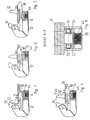
- switch tongue assigned to the stock rail (10) (12) via guide elements with at least one roller element (14) interacts that the switch tongue (12) in its adjacent position (Fig. 3, 7. 12, 16) and in their remote position (Fig. 2, 5, 10, 14) on a sliding chair (16) is supported and fixed there or locked and in between them Positions located area, i.e. when pivoting from the locked in the open position to the sliding chair (16) or a corresponding pad is spaced. These positions can be seen in FIGS. 2, 6, 11 and 15.
- roller element or elements are used (14) from bow-shaped brackets (17), which in the usual way with the Stock rail (10) can be connected.
- the supports (17) supporting the roller elements (14) are associated with support such as threshold, so that a decoupling from the stock rail (10).
- the roller element (14) is arranged stationary with respect to the switch tongue (12).
- a guide element (18) extends from the switch tongue (12) with the underside of the foot (20) of the switch tongue (12) connected as screwed or welded. That too as a guide plate too
- Designating guide element (18) has a guide track or line on the roller side (22), which is cranked.
- the guideline or guideway is set (22) from a central section (24) and two outer sections (26) and (28) together, which lie in mutually offset planes.
- the section (24) projects in the direction of the roller element (14) in order to Interact with this by spacing the underside of the tongue base (12) to the sliding chair (16) between the lying and lying position of the switch tongue (12) to effect.
- the sections run (26) and (28) in a common direction with respect to section (24) the stock rail or the switch tongue (12) offset plane.
- FIG. 4 illustrates on the one hand the plate-shaped Guide element (18) and on the other hand that the bracket (17) from two to each other spaced bow-shaped cheeks (34) and (36), in which the Roller element (14) is mounted.
- the cheeks (34), (36) can be connected by a base plate (38) and stiffeners (40) exhibit.
- FIGS. 5 to 9 differs from 1 to 4 in that the roller element (14) in a cage (42) is mounted, which is vertically displaceable in the holder (17) and on a Spring element (44) can be supported, which has both carrying and damping functions exercises.
- the spring element (44) can be an elastomer spring.
- the spring element (44) adjusts itself so that when the switch tongue (12) between the on and off position, ie in the area in which is normally a distance from the sliding chair (16) according to Fig. 6 takes place during an incorrect travel (indicated by a wheel (46) on the switch tongue (12)) damping takes place such that the switch tongue (12) without destruction the roller element (14) comes to rest on the sliding chair (16).
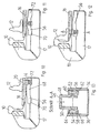
- FIGS. 10 to 17 also apply on the one hand the teaching realizes that the switch tongue (12) in the on and off position the sliding chair (16) rests and between these positions to the sliding chair (16) is spaced and on the other hand in the end positions via the roller element (14) is locked.
- the roller element starts from the switch tongue (12).
- roller element (14) in the true sense.
- the rollers (52) and (54) each run in a guideway (56) and (58) are limited by webs (60) and (62) or (64) and (66).
- the webs (60), (62), (64) and (66) go according to the embodiment of FIGS. 10 to 13 from the Inside of the bow-shaped cheeks (34), (36) of the holder (18). Of the clear distance between the webs (60) and (62) or (64) and (66) is greater than the diameter of the rollers (52) and (45).
- the roller element (14) extending from the holder (46) arrives, So the rollers (52), (54) from the outer section (70) and (72) to the middle section (68).
- the rollers (52) and (54) are based on the Web (62) and (66).
- the switch tongue is raised (12) (Fig. 11), so that a spacing from the sliding chair (16) is ensured.
- rollers (52) and (54) rest on the webs (60) and (64) such that the foot (20) of the switch tongue (12) to the sliding chair (16) attracted, that is, held down on it, so that an initiation of Vibrations cannot lead to impacts on the sliding chair (16).
- a safe hold down of the tongue (12) in its end positions with simultaneous Damping is by the measure of the embodiment shown in FIGS. 14 to 18 can be reached, at the same time ensuring in the event of incorrect driving (FIG. 18), that the roller element (16), that is, which are supported on the webs (62) and (66) Rollers (52) and (54) or their axes are not damaged or destroyed can be.
- the guideways (56) and (58) via spring elements (74) and (76) supported, which emanate from a holding plate (78) in some areas in a cage is movable.
- the cage is laterally by ironing cheeks (80) and (82) a holder (84) limits that of the holder (17) from the basic one Structure corresponds.
- the spring elements (74) and (76) can be elastomer springs.
- the spring element (76) to be designated as a compression spring is on the one hand connected to the Carrier plate (78) and on the other hand with the bottom (86) of the cage or Bracket (84) connected.
- the spring element to be referred to as a tension spring (74) extends between sleeves (96) and (98), one of which is from the carrier plate (78) and the other of one having the guideways (56) and (58) Device (88), namely the bottom surface (90).
- the spring elements (74) and (76) perform different functions.
- the carrier plate (78) lies on one Stop (100), (102) on the inner wall of the cage, that is Insides of the cheeks (80) and (22) of the holder (84).
- the spring element (76) acts as Compression spring, can between the stop (100), (102) and Move the bottom area (86) of the cage.
- the spring element (74) rests Block.
- the bottom (90) of the receptacle (88) lies on that of the carrier plate (78) outgoing sleeve (96), so that the spring properties of the spring element (74) are prevented.
- the base element (90) of the receptacle (88) is towards the edges (92), (94) of the cage or the holder (84) spaced apart.
- the rollers (52) and (54) can otherwise be destroyed Impact-like loads do not occur because the compression spring (76) is effective is.
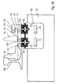
- the recording (115) is open Spring devices (103) and (105) supported, which in turn on the bracket (106) are attached, which in the exemplary embodiment is based on a threshold (110).
- the holder (106) can be directed towards or from a stock rail (108) be moved.
- side legs of the holder (106) have elongated holes (112) on that of the bracket (106) with the threshold (110) connecting Fasteners such as screws can be enforced.
- the receptacle (115) itself preferably consists of two U-shaped ones Cheeks in which the roller elements (107), (109), (111) and (113) are mounted and the over e.g. a flat section are connected to the spring devices (103) and (105) is attached.
- FIG. 20 shows a switch tongue (114) to be assigned to the stock rail (108) on the one hand in the adjacent (solid line) and on the other hand in the remote position (dash-dash line).
- a portion of the switch tongue foot (116) rests between the rollers (111) and (113), ie between the short leg (118) and the long leg (101) in side view U-shaped receptacle (115) of the roller elements (107), (109), (111) and (113).
- This measure causes the switch tongue (114) in the remote position is also virtually locked to beat this to exclude.
- Each spring device (103) or (105) consists of an upper and a lower plate element (124), preferably made of metal, and (126) and a carrier plate (128) extending between them, which is supported by the Bracket (106) goes out. Between the carrier plate (128) and the top plate (124) on the one hand and between the carrier plate (128) and the lower one, ie the Stock rail (108) remote plate (126) on the other hand, the Spring elements (122) or (120) of different stiffnesses.
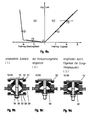
- the stiffness of the spring elements (120) and (122), which are Elastomer springs that are with the plates (124), (126), (128) or with connected to these outgoing, but unspecified sections like are vulcanized, can be seen in principle in Fig. 19a.
- the spring elements (120) and (122) are mechanical through a connecting element (130) coupled. This passes through the spring devices (103) and (105) centrally.
- it is a screw (130) with its plate-shaped head (132) abuts the outside of the plate (124) and its nut (134) abuts the outside of the plate (126) to pass through Tighten the screw (130) the effective length of the screw (130) between adjust the plates (124) and (126).
- the spring element (120) is a damping spring with variable stiffness.
- the spring element (120) preferably has one progressive characteristic curve, as the left part of FIG. 19a is intended to illustrate.
- the upper spring element (122) close to the stock rail (108) has one Spring characteristic with constant or essentially constant stiffness on and should perform the actual load-bearing function.
- the spring device (103), (105) has a position which corresponds to Fig. 19b.
- the plates (124) and (126), one of which is the Support spring (122) and on the other hand the damping spring (120) are out Carrier plate (128) spaced.
- this state coincides with the coordinate origin of the diagram together, in which the force (tension / load) against the Travel is applied.
- the position in which the switch tongue is shown is shown purely schematically in FIG. 19d (114) is supported on the roller elements (107), (109), (111).
- the damping spring (120) is a spring travel - in Fig. 19a purely exemplary 5 units - relieved.
- the suspension spring (122) is moved by the same travel, i.e. in the drawing stretched by 5 travel units. This position corresponds to the point 3 in Fig. 19a, which is the working point.
- vibrations are now introduced into the switch tongue (114), they can completely absorbed by the spring devices (103) and (105) and in particular be damped via the spring element (120) without a Beating occurs; because the working point 3 is so in relation to the spring characteristics set that the damping spring (120) can not reach its block position.
- both the spring tongue is loaded and relieved (114) ensures the resilient state of the spring devices (103) and (105).
Landscapes
- Vibration Prevention Devices (AREA)
Claims (10)
- Dispositif à rouleau destiné à une seconde partie de voie (12) réglable par rapport à une première partie de voie (10) et qui peut s'appuyer sur un élément à rouleau (14), cette seconde partie (12), quand elle est en contact avec la première partie ou écartée de celle-ci, étant en appui sur un support inférieur (18) tel qu'une plaque de glissement dont elle est de préférence espacée lorsqu'elle se trouve entre les positions précédentes,
caractérisé en ce que
l'élément à rouleau (14) est en appui sur au moins deux éléments élastiques (74, 76) accouplés mécaniquement de manière que dans la position au contact ou écartée de la seconde pièce de voie (12), un seul des éléments élastiques (74) intervient en ressort de traction tandis qu'entre les deux positions précédentes, l'autre élément de ressort (76) intervient en ressort de poussée. - Dispositif à rouleau destiné à une seconde partie de voie (114) réglable par rapport à une première partie de voie (108) et qui peut s'appuyer sur un élément à rouleau (107, 109, 111, 113), cette seconde partie (114), quand elle occupe une première position dans laquelle elle est en contact avec la première partie de voie, étant en appui sur un support inférieur tel qu'une plaque de glissement dont elle est espacée quand elle n'occupe pas cette première position,
caractérisé en ce que
l'élément à rouleau (107, 109, 111, 113) est en appui sur au moins deux éléments élastiques (120, 122) ayant des caractéristiques différentes telles qu'un élément élastique (122) présente une raideur essentiellement constante tandis que l'autre élément élastique (120) présente une raideur variable, les deux éléments étant mécaniquement accouplés de manière que quand l'élément à rouleau (107, 101, 111) est chargé par la seconde partie de voie (114), chaque élément élastique dispose d'une capacité élastique. - Dispositif à rouleau selon la revendication 2,
caractérisé en ce que
les éléments élastiques (120, 122) s'étendent sur les côtés opposés d'un élément porteur (128) et un élément de liaison (130) permet de faire varier leur espacement, un élément élastique (120) assurant l'amortissement avec une raideur variable s'étendant sur le côté de l'élément porteur éloigné de la seconde partie de rail telle qu'une aiguille (114) et étant tiré vers cet élément porteur par l'élément de liaison quand l'élément de rouleau (107, 109, 111) n'est pas chargé, de sorte qu'un effet élastique est exclu totalement ou en grande partie tandis que chacun des éléments élastiques, quand l'élément de rouleau est chargé, présente des déplacements élastiques absorbant les contraintes usuelles supplémentaires de charge et de décharge de l'élément à rouleau. - Dispositif à rouleau selon au moins une des revendications précédentes,
caractérisé en ce que
la première partie de rail est une contre-aiguille (10), ou une patte de lièvre, tandis que la seconde partie est une aiguille (12) ou une pointe de coeur de croisement. - Dispositif à rouleau selon au moins une des revendications précédentes,
caractérisé en ce que
l'élément à rouleau (107, 109, 111, 113) part d'un logement (115) dans lequel la seconde partie de voie (114) peut être fixée en position écartée, ce logement partant de préférence directement ou indirectement du support inférieur tel qu'une traverse (110). - Dispositif à rouleau selon au moins une des revendications précédentes,
caractérisé en ce que
les éléments élastiques (120, 122) sont en élastomères. - Dispositif à rouleau selon au moins une des revendications précédentes,
caractérisé en ce queles éléments élastiques (74, 76) partent d'une plaque porteuse (78) commune, pouvant coulisser dans un logement (84) et venir s'appliquer sur une butée (100, 102),entre la plaque porteuse et la face (86) du logement située vers le sol se trouve un premier élément élastique (76) agissant en poussée, tandis qu'un deuxième élément élastique (74) agissant essentiellement en traction est monté entre la plaque porteuse et un élément (88) pouvant être espacé du logement et présentant une piste de guidage (56, 58),la seconde partie de voie (12), lorsqu'elle est dans sa position de contact ou dans sa position écartée peut être maintenue vers le bas par le second élément élastique (74) tandis que, dans les positions intermédiaires, elle peut être soutenue par l'élément élastique (76). - Dispositif à rouleau selon au moins une des revendications précédentes,
caractérisé en ce que
le ressort de traction (74), lorsqu'il est tendu, accumule une énergie potentielle égale ou supérieure à l'énergie cinétique qui peut être induite dans la seconde partie de rail (12), dans des conditions normales. - Dispositif à rouleau selon au moins une des revendications précédentes,
caractérisé en ce que
la seconde partie de rail (12), quand elle occupe sa position de contact ou sa position écartée, est maintenue vers le bas sur le support inférieur (18), par l'élément à rouleau (14). - Dispositif à rouleau selon au moins une des revendications précédentes,
caractérisé en ce que
l'élément à rouleau (14) part d'un dispositif de maintien relié à un support inférieur tel qu'une traverse.
Priority Applications (1)
| Application Number | Priority Date | Filing Date | Title |
|---|---|---|---|
| EP93915931A EP0652996B1 (fr) | 1992-07-22 | 1993-07-16 | Dispositif a rouleau |
Applications Claiming Priority (6)
| Application Number | Priority Date | Filing Date | Title |
|---|---|---|---|
| EP92112528A EP0532860B1 (fr) | 1991-07-25 | 1992-07-22 | Support à roulement pour l'aiguille mobile coopérant avec la contre-aiguille d'un aiguillage |
| DE4224158 | 1992-07-22 | ||
| EP92112528 | 1992-07-22 | ||
| DE4224158A DE4224158A1 (de) | 1992-07-22 | 1992-07-22 | Rolleneinrichtung |
| EP93915931A EP0652996B1 (fr) | 1992-07-22 | 1993-07-16 | Dispositif a rouleau |
| PCT/EP1993/001872 WO1994002682A1 (fr) | 1992-07-22 | 1993-07-16 | Dispositif a rouleau |
Publications (2)
| Publication Number | Publication Date |
|---|---|
| EP0652996A1 EP0652996A1 (fr) | 1995-05-17 |
| EP0652996B1 true EP0652996B1 (fr) | 1999-06-02 |
Family
ID=27203997
Family Applications (1)
| Application Number | Title | Priority Date | Filing Date |
|---|---|---|---|
| EP93915931A Expired - Lifetime EP0652996B1 (fr) | 1992-07-22 | 1993-07-16 | Dispositif a rouleau |
Country Status (1)
| Country | Link |
|---|---|
| EP (1) | EP0652996B1 (fr) |
Families Citing this family (1)
| Publication number | Priority date | Publication date | Assignee | Title |
|---|---|---|---|---|
| ES2617562B2 (es) * | 2017-03-10 | 2018-04-12 | Jez Sistemas Ferroviarios, S.L. | Dispositivo de maniobra para desvíos ferroviarios con corazón de punta móvil |
-
1993
- 1993-07-16 EP EP93915931A patent/EP0652996B1/fr not_active Expired - Lifetime
Also Published As
| Publication number | Publication date |
|---|---|
| EP0652996A1 (fr) | 1995-05-17 |
Similar Documents
| Publication | Publication Date | Title |
|---|---|---|
| EP0964100B1 (fr) | Support à roulement pour l'aiguille mobile coopérant avec la contre-aiguille d'un aiguillage | |
| DE2729692C3 (de) | Vorrichtung zum Einbau in eine Bahngleisweiche | |
| DE202006020567U1 (de) | System zur Befestigung einer Schiene | |
| DE1257817B (de) | Schienenbefestigung auf Betonschwellen od. dgl. | |
| WO1994002682A1 (fr) | Dispositif a rouleau | |
| DE102012111320B3 (de) | Vorrichtung zur Spurführung von auf Schienen beweglichen Geräten und/oder Maschinen | |
| DE102008052152A1 (de) | Weichenzungenhebe- und Rollvorrichtung | |
| DE4410086C2 (de) | Rollvorrichtung für eine Weichenkonstruktion bei Eisenbahnen im Gleisoberbau | |
| EP1060097B1 (fr) | Frein de voie, notamment frein de maintien | |
| DE4112926A1 (de) | Befestigung von schienen in weichen | |
| EP0745161B1 (fr) | Dispositif a galets | |
| DE4211366C2 (de) | Schienenlager | |
| EP0652996A1 (fr) | Dispositif a rouleau | |
| DE19812795C1 (de) | Gleitstuhl für eine Schienenweiche | |
| WO1994026976A1 (fr) | Pointe de c×ur de croisement | |
| DE10110868B4 (de) | Rollvorrichtung | |
| DE10128844B4 (de) | Vorrichtung zum Befestigen von Schienen auf einem festen Untergrund | |
| DE815354C (de) | Unterlagsplatte mit Federkeilen zur Befestigung von Eisenbahnschienen | |
| DE4224158A1 (de) | Rolleneinrichtung | |
| DE3427439A1 (de) | Hoehenverstellbare tischanordnung, insbesondere schiesspritsche | |
| DE4031540A1 (de) | Schienenlager | |
| DE1088524B (de) | Schienenbefestigung fuer Breitfussschienen mittels buegelfoermiger Federklammern | |
| DE4214756A1 (de) | Dehnungsstoß für ein Gleisteil | |
| DE2741372C2 (de) | Schwingungsdämpfender Untersetzer | |
| DE1021003B (de) | Schienenbefestigungsvorrichtung mit hoehenmaessiger Einrichtmoeglichkeit fuer die Schiene |
Legal Events
| Date | Code | Title | Description |
|---|---|---|---|
| PUAI | Public reference made under article 153(3) epc to a published international application that has entered the european phase |
Free format text: ORIGINAL CODE: 0009012 |
|
| 17P | Request for examination filed |
Effective date: 19950204 |
|
| AK | Designated contracting states |
Kind code of ref document: A1 Designated state(s): AT DE DK FR IT NL SE |
|
| RBV | Designated contracting states (corrected) |
Designated state(s): AT DE DK FR IT NL SE |
|
| 17Q | First examination report despatched |
Effective date: 19971002 |
|
| GRAG | Despatch of communication of intention to grant |
Free format text: ORIGINAL CODE: EPIDOS AGRA |
|
| GRAG | Despatch of communication of intention to grant |
Free format text: ORIGINAL CODE: EPIDOS AGRA |
|
| GRAG | Despatch of communication of intention to grant |
Free format text: ORIGINAL CODE: EPIDOS AGRA |
|
| GRAH | Despatch of communication of intention to grant a patent |
Free format text: ORIGINAL CODE: EPIDOS IGRA |
|
| RAP1 | Party data changed (applicant data changed or rights of an application transferred) |
Owner name: BWG BUTZBACHER WEICHENBAU GESELLSCHAFT MBH & CO. K |
|
| GRAH | Despatch of communication of intention to grant a patent |
Free format text: ORIGINAL CODE: EPIDOS IGRA |
|
| GRAA | (expected) grant |
Free format text: ORIGINAL CODE: 0009210 |
|
| AK | Designated contracting states |
Kind code of ref document: B1 Designated state(s): AT DE DK FR IT NL SE |
|
| PG25 | Lapsed in a contracting state [announced via postgrant information from national office to epo] |
Ref country code: SE Free format text: THE PATENT HAS BEEN ANNULLED BY A DECISION OF A NATIONAL AUTHORITY Effective date: 19990602 Ref country code: NL Free format text: LAPSE BECAUSE OF FAILURE TO SUBMIT A TRANSLATION OF THE DESCRIPTION OR TO PAY THE FEE WITHIN THE PRESCRIBED TIME-LIMIT Effective date: 19990602 Ref country code: IT Free format text: LAPSE BECAUSE OF FAILURE TO SUBMIT A TRANSLATION OF THE DESCRIPTION OR TO PAY THE FEE WITHIN THE PRE;WARNING: LAPSES OF ITALIAN PATENTS WITH EFFECTIVE DATE BEFORE 2007 MAY HAVE OCCURRED AT ANY TIME BEFORE 2007. THE CORRECT EFFECTIVE DATE MAY BE DIFFERENT FROM THE ONE RECORDED.SCRIBED TIME-LIMIT Effective date: 19990602 |
|
| REF | Corresponds to: |
Ref document number: 180849 Country of ref document: AT Date of ref document: 19990615 Kind code of ref document: T |
|
| REF | Corresponds to: |
Ref document number: 59309632 Country of ref document: DE Date of ref document: 19990708 |
|
| PG25 | Lapsed in a contracting state [announced via postgrant information from national office to epo] |
Ref country code: DK Free format text: LAPSE BECAUSE OF FAILURE TO SUBMIT A TRANSLATION OF THE DESCRIPTION OR TO PAY THE FEE WITHIN THE PRESCRIBED TIME-LIMIT Effective date: 19990902 |
|
| ET | Fr: translation filed | ||
| PLBE | No opposition filed within time limit |
Free format text: ORIGINAL CODE: 0009261 |
|
| STAA | Information on the status of an ep patent application or granted ep patent |
Free format text: STATUS: NO OPPOSITION FILED WITHIN TIME LIMIT |
|
| 26N | No opposition filed | ||
| PGFP | Annual fee paid to national office [announced via postgrant information from national office to epo] |
Ref country code: AT Payment date: 20030703 Year of fee payment: 11 |
|
| PGFP | Annual fee paid to national office [announced via postgrant information from national office to epo] |
Ref country code: DE Payment date: 20030710 Year of fee payment: 11 |
|
| PGFP | Annual fee paid to national office [announced via postgrant information from national office to epo] |
Ref country code: FR Payment date: 20030711 Year of fee payment: 11 |
|
| PG25 | Lapsed in a contracting state [announced via postgrant information from national office to epo] |
Ref country code: AT Free format text: LAPSE BECAUSE OF NON-PAYMENT OF DUE FEES Effective date: 20040716 |
|
| PG25 | Lapsed in a contracting state [announced via postgrant information from national office to epo] |
Ref country code: DE Free format text: LAPSE BECAUSE OF NON-PAYMENT OF DUE FEES Effective date: 20050201 |
|
| PG25 | Lapsed in a contracting state [announced via postgrant information from national office to epo] |
Ref country code: FR Free format text: LAPSE BECAUSE OF NON-PAYMENT OF DUE FEES Effective date: 20050331 |
|
| REG | Reference to a national code |
Ref country code: FR Ref legal event code: ST |