EP0652998B1 - Vorrichtung zum trocknen von grossen flächen - Google Patents
Vorrichtung zum trocknen von grossen flächen Download PDFInfo
- Publication number
- EP0652998B1 EP0652998B1 EP94915630A EP94915630A EP0652998B1 EP 0652998 B1 EP0652998 B1 EP 0652998B1 EP 94915630 A EP94915630 A EP 94915630A EP 94915630 A EP94915630 A EP 94915630A EP 0652998 B1 EP0652998 B1 EP 0652998B1
- Authority
- EP
- European Patent Office
- Prior art keywords
- air
- nozzle
- outlet
- arrangement
- drying
- Prior art date
- Legal status (The legal status is an assumption and is not a legal conclusion. Google has not performed a legal analysis and makes no representation as to the accuracy of the status listed.)
- Expired - Lifetime
Links
- 238000001035 drying Methods 0.000 title claims abstract description 10
- 150000001875 compounds Chemical class 0.000 claims description 11
- 239000000446 fuel Substances 0.000 claims description 8
- 229920001187 thermosetting polymer Polymers 0.000 claims description 6
- 239000010426 asphalt Substances 0.000 claims 1
- 239000011295 pitch Substances 0.000 abstract description 3
- 238000007789 sealing Methods 0.000 abstract description 3
- 244000025254 Cannabis sativa Species 0.000 abstract description 2
- 239000002352 surface water Substances 0.000 abstract description 2
- XLYOFNOQVPJJNP-UHFFFAOYSA-N water Substances O XLYOFNOQVPJJNP-UHFFFAOYSA-N 0.000 description 5
- ATUOYWHBWRKTHZ-UHFFFAOYSA-N Propane Chemical compound CCC ATUOYWHBWRKTHZ-UHFFFAOYSA-N 0.000 description 4
- 235000004443 Ricinus communis Nutrition 0.000 description 2
- 238000004519 manufacturing process Methods 0.000 description 2
- 239000001294 propane Substances 0.000 description 2
- 241000196324 Embryophyta Species 0.000 description 1
- 240000008821 Menyanthes trifoliata Species 0.000 description 1
- 238000001125 extrusion Methods 0.000 description 1
- 239000000945 filler Substances 0.000 description 1
- 238000010438 heat treatment Methods 0.000 description 1
- 239000007787 solid Substances 0.000 description 1
- 229910001220 stainless steel Inorganic materials 0.000 description 1
- 239000010935 stainless steel Substances 0.000 description 1
- 230000003068 static effect Effects 0.000 description 1
Images


Classifications
-
- E—FIXED CONSTRUCTIONS
- E01—CONSTRUCTION OF ROADS, RAILWAYS, OR BRIDGES
- E01C—CONSTRUCTION OF, OR SURFACES FOR, ROADS, SPORTS GROUNDS, OR THE LIKE; MACHINES OR AUXILIARY TOOLS FOR CONSTRUCTION OR REPAIR
- E01C23/00—Auxiliary devices or arrangements for constructing, repairing, reconditioning, or taking-up road or like surfaces
- E01C23/14—Auxiliary devices or arrangements for constructing, repairing, reconditioning, or taking-up road or like surfaces for heating or drying foundation, paving, or materials thereon, e.g. paint
-
- E—FIXED CONSTRUCTIONS
- E01—CONSTRUCTION OF ROADS, RAILWAYS, OR BRIDGES
- E01C—CONSTRUCTION OF, OR SURFACES FOR, ROADS, SPORTS GROUNDS, OR THE LIKE; MACHINES OR AUXILIARY TOOLS FOR CONSTRUCTION OR REPAIR
- E01C23/00—Auxiliary devices or arrangements for constructing, repairing, reconditioning, or taking-up road or like surfaces
- E01C23/16—Devices for marking-out, applying, or forming traffic or like markings on finished paving; Protecting fresh markings
- E01C23/20—Devices for marking-out, applying, or forming traffic or like markings on finished paving; Protecting fresh markings for forming markings in situ
Definitions
- This invention relates to apparatus for drying extensive surfaces.
- Road markings are laid as a hot molten thermosetting plastics compound, which includes a filler. As the compound cools it sets to a solid which is intended to adhere to the surface of the road. Unfortunately, even a very small amount of moisture on the road surface prevents the adhesion so that many working hours are lost each year while road marking gangs wait for the surface to dry.
- One attempt to dry the surface involves a hollow lance with a plenum chamber at one end from which open a series of small orifices. Air under high pressure is supplied to the plenum chamber by a compressor which is readily available to a road working crew.
- the plenum chamber is also supplied with a fuel, e.g. propane, which is burnt in the compressed air in the chamber.
- propane e.g. propane
- apparatus for drying extensive surfaces comprising an air knife directed at the surface, the air knife comprising one or more nozzles which has or have an outlet comprising an elongate slot ; means for delivering air to the nozzle(s) at a high volume flow rate and low pressure, the total cross sectional area of the nozzle(s) at its or their outlet being approximately equal to the cross sectional area of the outlet of the blower means for delivering air through which the outlet air is delivered, said apparatus either including means for transporting the entire apparatus across the surface, or being attached to a plant for treating the dried surface.
- the arrangement efficiently strips water off the surface and the noise may be kept down to a level acceptable to the work force.
- the apparatus may be used to clear surface water from roads, or sports areas before laying tarmac or markings, or for drying pitches whether grass or synthetic. Other uses may well occur to the reader.
- a much preferred embodiment of the invention includes an arrangement to heat the air supplied to the nozzle. Surprisingly, sufficient heat can easily be provided to dry the surface completely, or sufficiently to lay road markings.
- the means for delivering air to the slot includes a blower driven by a motor mounted in or on the apparatus.
- the blower can be a standard product.
- the motor may be a petrol or diesel unit.
- the arrangement to heat the air preferably includes a heater comprising a chamber, a burner to burn fuel in said air in the chamber, and means mounted in or on the apparatus for storing the fuel and supplying it to the burner.
- a heater comprising a chamber, a burner to burn fuel in said air in the chamber, and means mounted in or on the apparatus for storing the fuel and supplying it to the burner.
- Previous proposals for air knives to use heated air have used electric heaters. That may be adequate for static apparatus in a factory environment, but is not suitable for mobile apparatus which is moved across extensive surfaces, e.g. many miles of roadway preparatory to marking a line or sealing a slot or groove.
- a jet engine constitutes both the arrangement to heat the air and also the means for delivering air to the slot.
- the engine may be a fan jet.
- the apparatus may be automotive or mounted on, say, wheels so that motive power is provided by a pedestrian.
- thermosetting compound may comprise tarmac or a compound for marking lines on the surface.
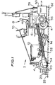
- a road marking vehicle 2 having road wheels 4, is driven by an engine 6, and is controlled by an operator seated at a position 8 where a steering wheel 10 and other controls are located.
- the vehicle has a heated hopper 12 for the thermosetting compound to be laid, and a laying head 14, for example an extrusion shoe (illustrated) or a screed box.
- the laying head is selectively operated to lay the compound on the road so as to provide the desired markings.
- the vehicle illustrated additionally has three air knives 20, illustrated generally in Figure 1 and more particularly in Figures 2 and 4 and 5.
- the air knives 20 are directed downwardly and forwardly at the road 22 ahead of the track that the laying head will follow.
- each air knife comprises a cylinder 24 closed at each end to provide a plenum chamber 26.
- An outlet is provided in the form of a rectangular slot 28 between plates 30 which direct air at high volume and low pressure downwardly and forwardly at the road 22.
- the plates should be manufacture to resist distortion from the high temperatures which will be obtained by the heating arrangement to be described.
- the plates are manufacture from thick plates of high grade stainless steel and, additionally, are bridged at intervals by weld so as to maintain their spacing.
- An inlet manifold 32 is provided in the form of a tapering tube to supply air to the plenum chambers. At its inlet end the manifold has a cross sectional area approximately equal to the total cross sectional area of all three slots 28. The manifold tapers towards the most forward of the air knives so that at its most forward end, it has a cross sectional area approximately equal to the area of the slot of that air knife. At the intermediate air knife the manifold has a cross sectional area approximately equal to the area of the outlet slots of two air knives.
- the air knives 20 are mounted in a frame 40 which is supported above the road by four castors 42 so that the air knives are positioned a predetermined distance from the road surface.
- the frame 40 is attached to the vehicle by arms 44 pivotally connected at one end to the vehicle (not shown) and at the other 46 to the frame. The air knives are thus moved along the road by the vehicle ahead of the laying head.
- the manifold inlet 34 is connected via a heater 54, and a flexible pipe 52 to the outlet of a blower unit 56.
- the cross sectional areas of the pipe 52, and thus the manifold inlet 34 and the total area of the slots 28, are chosen each to approximately equal the cross sectional area of the outlet 58 of the blower 56.
- the blower is driven by a petrol engine 60, the two being mounted on a platform 62 attached to the vehicle.
- a cross section of the heater is shown in Figure 3.
- the heater has a chamber 70 which expands from an inlet 72, which has a cross sectional area equal to that of the pipe 52, to a larger cross sectional area in which a burner 74 is mounted by a perforated conical support 76.
- Propane, or in other examples other fuel is supplied to the burner from a container 78 mounted at the rear of the vehicle.
- the fuel is ignited by a spark plug 80.
- a flame failure device including a sensor 82 operates to cut the fuel supply if the temperature drops indicating the flame has gone out.
- the chamber 70 reduces in cross sectional area to match that of the inlet to the manifold 32.
- Operation of the engine 60 to drive the blower 56 produces a high volume flow of low pressure air at the air knives 20 distinct, say, from the low volume high pressure air supply which is provided by a compressor.
- the air knives will clear loose water from the road as the vehicle is driven at a surprisingly high rate. Without operation of the heater the road would remain damp, although free of loose water, and prevent the adhesion of road marking compound.
- the drying apparatus may have utility in other applications, however.
- One example is to clear loose water from, say, a sports pitch or race track.
- Operation also of the heater will dry the surface more or less completely: sufficient to allow road markings to be laid. In one example we found the temperature of the air at the outlets of the air knives to be about 750°C.
- FIG. 6 An another example is illustrated in part in Figures 6 and 7.
- the main difference is an improved burner 74.
- this is in the form of a ring burner from which we have obtained a temperature at the outlets of the air knives of about 900°C.
- the low pressure high volume air could be both provided and heated by a fan jet.
- the apparatus may be controlled by, or pushed by, a pedestrian operator.
- a pedestrian operator Such an arrangement is illustrated in Figure 8.
- the primary function of the apparatus is to dry the surface, e.g. the road 22.
- Subsequent treatment of the surface e.g. marking with a line, sealing a slot or groove, laying tarmac etc, would be carried out separately by hand or by another machine not illustrated.
- the apparatus is mobile, having a tubular chassis 100 supported on a pair of wheels 102, rotatable about a common axis, and a pair of castor wheels 104.
- the burner 54, pipe 52, blower 56, engine 60 and gas supply 78 are mounted on the chassis 100 and are similar to those of Figure 1, except that the engine is gas fuelled from the same supply 78 as the burner.
- the specific arrangement of air knives is different in that a manifold 106 feeds heated air to two air knives 20 mounted one behind the other.
- Other pedestrian control apparatus may be automotive and/or may include equipment for treating the surface, e.g. for making a road with lines.
Landscapes
- Engineering & Computer Science (AREA)
- Architecture (AREA)
- Civil Engineering (AREA)
- Structural Engineering (AREA)
- Drying Of Solid Materials (AREA)
- Road Repair (AREA)
- Processing And Handling Of Plastics And Other Materials For Molding In General (AREA)
Claims (10)
- Vorrichtung zum Trocknen von großen Flächen, mit einem auf die Oberfläche gerichteten Luftmesser, wobei das Luftmesser eine oder mehrere Düsen enthält, welche einen Auslaß mit einem länglichen Schlitz aufweist oder aufweisen; Mitteln zum Zuführen von Luft zu der/den Düse(n) mit einer hohen Volumenflußrate und niedrigem Druck, wobei die gesamte Querschnittsfläche der Düse(n) an ihrem Auslaß oder ihren Auslässen etwa gleich der Querschnittsfläche des Auslasses der Gebläsemittel zum Zuführen der Luft ist, durch welche die Auslaßluft zugeführt wird, wobei die Vorrichtung entweder Mittel zum Transportieren der gesamten Vorrichtung über die Oberfläche enthält oder an einer Einrichtung zur Behandlung der getrockneten Oberfläche angebracht ist.
- Vorrichtung nach Anspruch 1,
gekennzeichnet durch eine Anordnung zum Heizen der der Düse zugeführten Luft. - Vorrichtung nach den Ansprüchen 1 oder 2,
dadurch gekennzeichnet, daß die Mittel zum Zuführen der Luft zu dem Schlitz ein Gebläse einschließen, angetrieben durch einen Motor, welcher in oder auf der Vorrichtung oder der technischen Einrichtung montiert ist. - Vorrichtung nach den Ansprüchen 2 oder 3,
dadurch gekennzeichnet, daß die Anordnung zum Heizen der Luft einschließt eine Heizung mit einer Kammer, einem Brenner, welcher ausgebildet ist, Brennstoff in der Luft in der Kammer zu verbrennen, und Mittel einschließt, die in oder auf der Vorrichtung zum Speichern des Brennstoffes montiert sind und diesen dem Brenner zuführen. - Vorrichtung nach Anspruch 2,
dadurch gekennzeichnet, daß ein Strahlmotor sowohl die Anordnung zum Heizen der Luft als auch die Mittel zum Zuführen der Luft zu dem Schlitz bildet. - Vorrichtung nach Anspruch 5,
dadurch gekennzeichnet, daß der Motor ein Gebläsestrahl ist. - Vorrichtung nach einem der vorstehenden Ansprüche,
dadurch gekennzeichnet, daß das oder jedes Luftmesser eine Verteilerkammer enthält, von der sich der Auslaß erstreckt. - Vorrichtung nach einem der vorstehenden Ansprüche, wenn die Vorrichtung an der Anlage angebracht ist,
dadurch gekennzeichnet, daß die Anlage Mittel einschließt zum Aufbringen einer Heißfixierverbindung auf die getrocknete Oberfläche. - Vorrichtung nach Anspruch 8,
dadurch gekennzeichnet, daß die Heißfixierverbindung ein gummiertes, gefülltes Bitumenprodukt oder eine Verbindung zum Markieren von Linien auf der Oberfläche ist. - Vorrichtung nach einem der vorstehenden Ansprüche,
dadurch gekennzeichnet, daß die Vorrichtung einen Eigenantrieb aufweist.
Applications Claiming Priority (3)
| Application Number | Priority Date | Filing Date | Title |
|---|---|---|---|
| GB939310333A GB9310333D0 (en) | 1993-05-19 | 1993-05-19 | Road surface drying |
| GB9310333 | 1993-05-19 | ||
| PCT/GB1994/001084 WO1994026982A1 (en) | 1993-05-19 | 1994-05-19 | Apparatus for drying extensive surfaces |
Publications (2)
| Publication Number | Publication Date |
|---|---|
| EP0652998A1 EP0652998A1 (de) | 1995-05-17 |
| EP0652998B1 true EP0652998B1 (de) | 1998-08-05 |
Family
ID=10735769
Family Applications (1)
| Application Number | Title | Priority Date | Filing Date |
|---|---|---|---|
| EP94915630A Expired - Lifetime EP0652998B1 (de) | 1993-05-19 | 1994-05-19 | Vorrichtung zum trocknen von grossen flächen |
Country Status (7)
| Country | Link |
|---|---|
| EP (1) | EP0652998B1 (de) |
| AT (1) | ATE169358T1 (de) |
| AU (1) | AU6726694A (de) |
| DE (1) | DE69412207T2 (de) |
| DK (1) | DK0652998T3 (de) |
| GB (1) | GB9310333D0 (de) |
| WO (1) | WO1994026982A1 (de) |
Cited By (1)
| Publication number | Priority date | Publication date | Assignee | Title |
|---|---|---|---|---|
| WO2012100026A1 (en) * | 2011-01-19 | 2012-07-26 | Graco Minnesota Inc. | Flame indicator |
Families Citing this family (11)
| Publication number | Priority date | Publication date | Assignee | Title |
|---|---|---|---|---|
| US6367469B1 (en) * | 2000-03-23 | 2002-04-09 | Zacho Bo Ravnsbaek | Jet blaster device |
| DE10238154A1 (de) * | 2002-08-15 | 2004-03-04 | Richard Rupprecht Gmbh | Gerät mit Abgaswärmerückführung zur Trocknung, Erhitzung und/oder zur Entfernung von Verunreinigungen von Verkehrsflächen |
| US9416503B1 (en) * | 2008-07-24 | 2016-08-16 | Isaac Sargent | Road surface seam sealing and drying apparatus |
| WO2012083111A1 (en) * | 2010-12-16 | 2012-06-21 | Textile Management Associates, Inc. | Seaming artificial turf |
| USD740860S1 (en) | 2013-02-01 | 2015-10-13 | National Association For Stock Car Auto Racing, Inc. | Road surface clearing apparatus |
| US9388542B2 (en) | 2013-02-01 | 2016-07-12 | National Association For Stock Car Auto Racing, Inc. | Apparatuses, systems, and methods for clearing a surface using pressurized air |
| US10024009B2 (en) | 2013-02-01 | 2018-07-17 | National Association For Stock Car Auto Racing, Inc. | Apparatuses, systems, and methods for clearing a surface using air |
| CN104532728A (zh) * | 2014-12-25 | 2015-04-22 | 浙江美通筑路机械股份有限公司 | 一种具有无线控制功能的热风式路面养护车控制装置 |
| DE202015005988U1 (de) | 2015-08-28 | 2015-10-26 | Andreas Rupprecht | Gerät mit einem Einstrom-Strahltriebwerk zur Trocknung, Erhitzung und/oder zum Entfernen von Verunreinigungen von Verkehrsflächen |
| ITUA20164130A1 (it) * | 2016-06-06 | 2017-12-06 | Ilaria Tessari | Dispositivo di asciugatura e pulizia di superfici erbose |
| US20200340193A1 (en) * | 2019-04-23 | 2020-10-29 | T&T R&D Co. | Movable surface drying apparatus |
Family Cites Families (4)
| Publication number | Priority date | Publication date | Assignee | Title |
|---|---|---|---|---|
| CH377871A (fr) * | 1962-07-11 | 1964-05-31 | Sogerep S A | Machine pour le séchage d'interstices tels que joints de dilatation d'éléments en béton |
| IT1077571B (it) * | 1977-01-12 | 1985-05-04 | Eigenmann Ludwig | Perfezionamento ai metodi per la formazione e la posa in opera meccanica di mezzi e materiali per seganletica stradale orizzontale,e relative macchine perfezionate |
| DE3814895A1 (de) * | 1988-05-03 | 1990-04-12 | Koch Christian | Strassentrocknungsgeraet |
| JP2861054B2 (ja) * | 1989-05-31 | 1999-02-24 | 大日本インキ化学工業株式会社 | 樹脂組成物、塗料、舖装材及び舖装構造体 |
-
1993
- 1993-05-19 GB GB939310333A patent/GB9310333D0/en active Pending
-
1994
- 1994-05-19 DK DK94915630T patent/DK0652998T3/da active
- 1994-05-19 WO PCT/GB1994/001084 patent/WO1994026982A1/en not_active Ceased
- 1994-05-19 AU AU67266/94A patent/AU6726694A/en not_active Abandoned
- 1994-05-19 EP EP94915630A patent/EP0652998B1/de not_active Expired - Lifetime
- 1994-05-19 DE DE69412207T patent/DE69412207T2/de not_active Expired - Fee Related
- 1994-05-19 AT AT94915630T patent/ATE169358T1/de not_active IP Right Cessation
Cited By (1)
| Publication number | Priority date | Publication date | Assignee | Title |
|---|---|---|---|---|
| WO2012100026A1 (en) * | 2011-01-19 | 2012-07-26 | Graco Minnesota Inc. | Flame indicator |
Also Published As
| Publication number | Publication date |
|---|---|
| DE69412207D1 (de) | 1998-09-10 |
| DE69412207T2 (de) | 1998-12-10 |
| ATE169358T1 (de) | 1998-08-15 |
| EP0652998A1 (de) | 1995-05-17 |
| DK0652998T3 (da) | 1999-05-10 |
| AU6726694A (en) | 1994-12-12 |
| WO1994026982A1 (en) | 1994-11-24 |
| GB9310333D0 (en) | 1993-06-30 |
Similar Documents
| Publication | Publication Date | Title |
|---|---|---|
| EP0652998A1 (de) | Vorrichtung zum trocknen von grossen flächen | |
| US4018540A (en) | Road maintenance machine | |
| CN107366394B (zh) | 热熔摊铺防水卷材机车 | |
| DE69523061T2 (de) | Verfahren und vorrichtung zur unkrautbekämpfung | |
| CA1317468C (en) | Maintaining an ice rink adjacent a side edge | |
| US3997276A (en) | Road maintenance machine and methods | |
| JP3745623B2 (ja) | 雑草の熱的枯死方法と装置 | |
| US3043200A (en) | Self-propelled concrete joint treating machine and method | |
| US2303812A (en) | Heater for road finishing machines | |
| US3108586A (en) | Snow removal equipment | |
| US11236479B2 (en) | Snow and ice melting device | |
| CA2056471C (en) | Infrared asphalt heater | |
| US8296968B2 (en) | Surface drying apparatus and method | |
| US6553693B1 (en) | Snow removal apparatus and method of using same | |
| DE60034595T2 (de) | Druckstrahlvorrichtung | |
| US9416503B1 (en) | Road surface seam sealing and drying apparatus | |
| DE102006026529B4 (de) | Fahrbares Gerät mit Asphaltflächenheizer, Walze, Igel-Fräse, Fugeneindrückrad zur Fugenherstellung oder-Reparatur | |
| US10689822B2 (en) | Soil conditioning apparatus and method | |
| GB1257475A (de) | ||
| CA1300417C (en) | Apparatus for reproducing the asphalt road surface | |
| GB2097844A (en) | Asphalt laying machines | |
| JP2000054336A (ja) | 地表処理車両 | |
| JP3416838B2 (ja) | アスファルト乳剤散布機械 | |
| US9085858B2 (en) | Road drying apparatus and method | |
| DE2809249A1 (de) | Strassenmarkierungsvorrichtung |
Legal Events
| Date | Code | Title | Description |
|---|---|---|---|
| PUAI | Public reference made under article 153(3) epc to a published international application that has entered the european phase |
Free format text: ORIGINAL CODE: 0009012 |
|
| AK | Designated contracting states |
Kind code of ref document: A1 Designated state(s): AT BE CH DE DK ES FR GB IE IT LI LU NL PT SE |
|
| 17P | Request for examination filed |
Effective date: 19950523 |
|
| 17Q | First examination report despatched |
Effective date: 19960109 |
|
| GRAG | Despatch of communication of intention to grant |
Free format text: ORIGINAL CODE: EPIDOS AGRA |
|
| GRAG | Despatch of communication of intention to grant |
Free format text: ORIGINAL CODE: EPIDOS AGRA |
|
| GRAH | Despatch of communication of intention to grant a patent |
Free format text: ORIGINAL CODE: EPIDOS IGRA |
|
| GRAH | Despatch of communication of intention to grant a patent |
Free format text: ORIGINAL CODE: EPIDOS IGRA |
|
| GRAA | (expected) grant |
Free format text: ORIGINAL CODE: 0009210 |
|
| AK | Designated contracting states |
Kind code of ref document: B1 Designated state(s): AT BE CH DE DK ES FR GB IE IT LI LU NL PT SE |
|
| PG25 | Lapsed in a contracting state [announced via postgrant information from national office to epo] |
Ref country code: IT Free format text: LAPSE BECAUSE OF FAILURE TO SUBMIT A TRANSLATION OF THE DESCRIPTION OR TO PAY THE FEE WITHIN THE PRESCRIBED TIME-LIMIT;WARNING: LAPSES OF ITALIAN PATENTS WITH EFFECTIVE DATE BEFORE 2007 MAY HAVE OCCURRED AT ANY TIME BEFORE 2007. THE CORRECT EFFECTIVE DATE MAY BE DIFFERENT FROM THE ONE RECORDED. Effective date: 19980805 Ref country code: ES Free format text: THE PATENT HAS BEEN ANNULLED BY A DECISION OF A NATIONAL AUTHORITY Effective date: 19980805 |
|
| REF | Corresponds to: |
Ref document number: 169358 Country of ref document: AT Date of ref document: 19980815 Kind code of ref document: T |
|
| REG | Reference to a national code |
Ref country code: CH Ref legal event code: NV Representative=s name: WILLIAM BLANC & CIE CONSEILS EN PROPRIETE INDUSTRI Ref country code: CH Ref legal event code: EP |
|
| REF | Corresponds to: |
Ref document number: 69412207 Country of ref document: DE Date of ref document: 19980910 |
|
| ET | Fr: translation filed | ||
| REG | Reference to a national code |
Ref country code: IE Ref legal event code: FG4D |
|
| PG25 | Lapsed in a contracting state [announced via postgrant information from national office to epo] |
Ref country code: SE Free format text: LAPSE BECAUSE OF FAILURE TO SUBMIT A TRANSLATION OF THE DESCRIPTION OR TO PAY THE FEE WITHIN THE PRESCRIBED TIME-LIMIT Effective date: 19981105 Ref country code: PT Free format text: LAPSE BECAUSE OF FAILURE TO SUBMIT A TRANSLATION OF THE DESCRIPTION OR TO PAY THE FEE WITHIN THE PRESCRIBED TIME-LIMIT Effective date: 19981105 |
|
| REG | Reference to a national code |
Ref country code: DK Ref legal event code: T3 |
|
| PG25 | Lapsed in a contracting state [announced via postgrant information from national office to epo] |
Ref country code: LU Free format text: LAPSE BECAUSE OF NON-PAYMENT OF DUE FEES Effective date: 19990519 Ref country code: IE Free format text: LAPSE BECAUSE OF NON-PAYMENT OF DUE FEES Effective date: 19990519 |
|
| PLBE | No opposition filed within time limit |
Free format text: ORIGINAL CODE: 0009261 |
|
| STAA | Information on the status of an ep patent application or granted ep patent |
Free format text: STATUS: NO OPPOSITION FILED WITHIN TIME LIMIT |
|
| 26N | No opposition filed | ||
| PGFP | Annual fee paid to national office [announced via postgrant information from national office to epo] |
Ref country code: AT Payment date: 20000519 Year of fee payment: 7 |
|
| PGFP | Annual fee paid to national office [announced via postgrant information from national office to epo] |
Ref country code: DK Payment date: 20000522 Year of fee payment: 7 |
|
| PGFP | Annual fee paid to national office [announced via postgrant information from national office to epo] |
Ref country code: CH Payment date: 20000525 Year of fee payment: 7 |
|
| PGFP | Annual fee paid to national office [announced via postgrant information from national office to epo] |
Ref country code: BE Payment date: 20000526 Year of fee payment: 7 |
|
| PGFP | Annual fee paid to national office [announced via postgrant information from national office to epo] |
Ref country code: NL Payment date: 20000530 Year of fee payment: 7 Ref country code: FR Payment date: 20000530 Year of fee payment: 7 Ref country code: DE Payment date: 20000530 Year of fee payment: 7 |
|
| PG25 | Lapsed in a contracting state [announced via postgrant information from national office to epo] |
Ref country code: DK Free format text: LAPSE BECAUSE OF NON-PAYMENT OF DUE FEES Effective date: 20010519 Ref country code: AT Free format text: LAPSE BECAUSE OF NON-PAYMENT OF DUE FEES Effective date: 20010519 |
|
| PG25 | Lapsed in a contracting state [announced via postgrant information from national office to epo] |
Ref country code: BE Free format text: LAPSE BECAUSE OF NON-PAYMENT OF DUE FEES Effective date: 20010531 |
|
| PG25 | Lapsed in a contracting state [announced via postgrant information from national office to epo] |
Ref country code: LI Free format text: LAPSE BECAUSE OF NON-PAYMENT OF DUE FEES Effective date: 20010618 Ref country code: CH Free format text: LAPSE BECAUSE OF NON-PAYMENT OF DUE FEES Effective date: 20010618 |
|
| BERE | Be: lapsed |
Owner name: S & S G.M.B.H. Effective date: 20010531 |
|
| PG25 | Lapsed in a contracting state [announced via postgrant information from national office to epo] |
Ref country code: NL Free format text: LAPSE BECAUSE OF NON-PAYMENT OF DUE FEES Effective date: 20011201 |
|
| REG | Reference to a national code |
Ref country code: GB Ref legal event code: IF02 |
|
| REG | Reference to a national code |
Ref country code: DK Ref legal event code: EBP |
|
| REG | Reference to a national code |
Ref country code: CH Ref legal event code: PL |
|
| PG25 | Lapsed in a contracting state [announced via postgrant information from national office to epo] |
Ref country code: FR Free format text: LAPSE BECAUSE OF NON-PAYMENT OF DUE FEES Effective date: 20020131 |
|
| NLV4 | Nl: lapsed or anulled due to non-payment of the annual fee |
Effective date: 20011201 |
|
| PG25 | Lapsed in a contracting state [announced via postgrant information from national office to epo] |
Ref country code: DE Free format text: LAPSE BECAUSE OF NON-PAYMENT OF DUE FEES Effective date: 20020301 |
|
| PGFP | Annual fee paid to national office [announced via postgrant information from national office to epo] |
Ref country code: GB Payment date: 20040510 Year of fee payment: 11 |
|
| PG25 | Lapsed in a contracting state [announced via postgrant information from national office to epo] |
Ref country code: GB Free format text: LAPSE BECAUSE OF NON-PAYMENT OF DUE FEES Effective date: 20050519 |
|
| GBPC | Gb: european patent ceased through non-payment of renewal fee |
Effective date: 20050519 |