EP0653190B1 - Geschütztes Skalpell - Google Patents
Geschütztes Skalpell Download PDFInfo
- Publication number
- EP0653190B1 EP0653190B1 EP94870174A EP94870174A EP0653190B1 EP 0653190 B1 EP0653190 B1 EP 0653190B1 EP 94870174 A EP94870174 A EP 94870174A EP 94870174 A EP94870174 A EP 94870174A EP 0653190 B1 EP0653190 B1 EP 0653190B1
- Authority
- EP
- European Patent Office
- Prior art keywords
- guard
- handle
- detent
- blade
- scalpel
- Prior art date
- Legal status (The legal status is an assumption and is not a legal conclusion. Google has not performed a legal analysis and makes no representation as to the accuracy of the status listed.)
- Expired - Lifetime
Links
- 238000001356 surgical procedure Methods 0.000 abstract description 6
- 210000005224 forefinger Anatomy 0.000 description 6
- 210000003813 thumb Anatomy 0.000 description 6
- 230000009471 action Effects 0.000 description 4
- 239000000463 material Substances 0.000 description 4
- 230000008901 benefit Effects 0.000 description 3
- 230000000295 complement effect Effects 0.000 description 3
- 230000000994 depressogenic effect Effects 0.000 description 3
- 238000005520 cutting process Methods 0.000 description 2
- 238000011017 operating method Methods 0.000 description 2
- 229920003023 plastic Polymers 0.000 description 2
- 230000001681 protective effect Effects 0.000 description 2
- 239000007787 solid Substances 0.000 description 2
- 102000007469 Actins Human genes 0.000 description 1
- 108010085238 Actins Proteins 0.000 description 1
- 208000035473 Communicable disease Diseases 0.000 description 1
- 241000700605 Viruses Species 0.000 description 1
- 230000035508 accumulation Effects 0.000 description 1
- 238000009825 accumulation Methods 0.000 description 1
- 230000006872 improvement Effects 0.000 description 1
- 208000015181 infectious disease Diseases 0.000 description 1
- 238000004519 manufacturing process Methods 0.000 description 1
- 239000002184 metal Substances 0.000 description 1
- 238000000034 method Methods 0.000 description 1
- 238000012986 modification Methods 0.000 description 1
- 230000004048 modification Effects 0.000 description 1
- 230000011664 signaling Effects 0.000 description 1
- 238000003466 welding Methods 0.000 description 1
- 210000000707 wrist Anatomy 0.000 description 1
Images







Classifications
-
- A—HUMAN NECESSITIES
- A61—MEDICAL OR VETERINARY SCIENCE; HYGIENE
- A61B—DIAGNOSIS; SURGERY; IDENTIFICATION
- A61B17/00—Surgical instruments, devices or methods
- A61B17/32—Surgical cutting instruments
- A61B17/3209—Incision instruments
- A61B17/3211—Surgical scalpels, knives; Accessories therefor
- A61B17/3213—Surgical scalpels, knives; Accessories therefor with detachable blades
-
- A—HUMAN NECESSITIES
- A61—MEDICAL OR VETERINARY SCIENCE; HYGIENE
- A61B—DIAGNOSIS; SURGERY; IDENTIFICATION
- A61B17/00—Surgical instruments, devices or methods
- A61B17/32—Surgical cutting instruments
- A61B17/3209—Incision instruments
- A61B17/3211—Surgical scalpels, knives; Accessories therefor
- A61B17/3217—Devices for removing or collecting used scalpel blades
-
- A—HUMAN NECESSITIES
- A61—MEDICAL OR VETERINARY SCIENCE; HYGIENE
- A61B—DIAGNOSIS; SURGERY; IDENTIFICATION
- A61B17/00—Surgical instruments, devices or methods
- A61B17/32—Surgical cutting instruments
- A61B17/3209—Incision instruments
- A61B17/3211—Surgical scalpels, knives; Accessories therefor
- A61B2017/32113—Surgical scalpels, knives; Accessories therefor with extendable or retractable guard or blade
Definitions
- the present invention relates to a surgical scalpel and, in particular, to a surgical scalpel having a retractable blade guard to protect against inadvertent nicks or cuts during a surgical procedure in an operating room.
- a guarded surgical scalpel wherein a guard is mounted on the scalpel handle for alternate sliding movement thereon between an advanced position in which the blade is covered and a retracted position in which the blade is exposed, thereby protecting against inadvertent nicks or cuts when the scalpel is being transferred from the surgeon to the nurse, and vice-versa, during a surgical procedure in an operating room.
- Detent means are provided between the guard and the handle, thereby defining the alternate positions of the guard with respect to the handle. Stop means are also provided between the guard and the handle to form a bearing guide between the guard and the handle and to preclude an accidental removal of the guard from the handle, the stop means being independent of the detent means.
- the stop means includes a pin carried transversely of the handle and riding in a closed longitudinal slot in the guard.
- the present invention constitutes an improved guarded surgical scalpel having a handle with a blade mounted thereon.
- the handle is substantially hollow and has a sliding guard telescopically mounted therein.
- the invention is directed to a guarded surgical scalpel having a handle with a blade mounted thereon wherein the handle is substantiallky hollow and wherein there is provided an inverted U-shaped guard telescopically mounted within the handle for sliding movement therein.
- a two-position resiliently biased detent means between the guard and the handle, thereby defining an advanced position of the guard in which the blade is substantially covered and an alternate retracted position of the guard in which the blade is exposed.
- a bearing guide means between the guard and the handle, the bearing guide means being independent of the detent means and providing a stop means limiting the sliding movement of the guard.
- the guard is formed as an inverted U-shaped channel, preferably having a pair of side walls, each of which has a preferably closed longitudinal slot formed therein for receiving the pin.
- the handle includes a lower member having a longitudinally-extending section constituting a cleat, and the cleat is provided with a rib for mounting the blade thereon.
- the present invention thus substantially reduces the risk of the surgeon, nurse or assistant inadvertently acquiring (or transmitting) an infectious disease, such as HIV or HBV, in the operating room or similar medical environment.
- Fig. 1 is a perspective View of an operating room or theater where a surgical scalpel will be utilized.
- Fig. 2A is an enlarged view of an unguarded scalpel, illustrating how an assistant may be cut or nicked when transferring the scalpel during an operating procedure.
- Fig. 2B is an enlarged view of an unguarded scalpel, corresponding substantially to Fig. 2A, but showing how the surgeon may be cut or nicked when transferring the scalpel.
- Fig. 3A illustrates how a conventional scalpel as disclosed in EP-A-555 196 protects the assistant's hand when passing the scalpel to the surgeon during an operation.
- Fig. 3B illustrates how the guard on the conventional scalpel is retracted by the surgeon --- with one hand --- to expose the blade.
- Fig. 3C illustrates how the guard is advanced by the surgeon --- again, with only one hand --- to cover the blade.
- Fig. 3D illustrates how the conventional guarded scalpel protects the assistant's hand when the surgeon passes the scalpel back to the assistant.
- Fig. 4 is a side elevation of the conventional scalpel with the protective guard in a first advanced position to cover the blade.
- Fig. 5 is a side elevation of the conventional scalpel with the protective guard in a second retracted position, thereby exposing the blade.
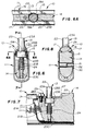
- Fig. 6 is a cross-sectional view, taken along lines 6-6 of Fig. 4, drawn to an enlarged scale, and showing the manually-releasable detent means for the guard.
- Fig. 6A is a cross-sectional view thereof, taken across the lines 6A-6A of Fig. 6, and showing the annular collar on the spring-loaded detent pin received in a respective detent pocket formed on the guard.
- Fig. 7 is a cross-sectional view taken along lines 7-7 of Fig. 6, showing the means for retaining the detent means on the body or handle of the scalpel.
- Fig. 8 is a cross-sectional view taken along lines 8-8 of Fig. 4, drawn to an enlarged scale, and showing the stop means for the guard.
- Fig. 9 is an exploded perspective view of the improved scalpel with its blade guard.
- Fig. 10 corresponds substantially to Fig. 6, but shows a cap or button on the releasable detent means for the blade, thereby providing a preferred tactile means and facilitating manual release of the detent means.
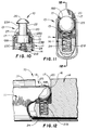
- Fig. 11 is an alternate embodiment of the detent means.
- Fig. 12 is a cross-sectional view thereof, taken along lines 12-12 of Fig. 11.
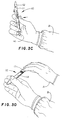
- Figs. 13A-13D show, respectively, the manner in which the guard may be manually retracted to expose the blade on the scalpel, and then advanced to cover the blade to protect against inadvertent cuts and nicks normally occasioned in transferring the scalpel from the nurse to the surgeon, and vice versa, during a surgical procedure; wherein the thumb engages the releasable detent pin (or button) and the forefinger is received in the cut-out formed in the bottom wall of the U-shaped sliding guard to alternately retract and advance the guard.
- Figs. 14A-14D correspond substantially to that of Figs. 13A-13D, but show an alternate manner for selectively and alternately retracting and advancing the sliding guard, wherein the forefinger releases the detent pin, and wherein the thumb engages the cut-out in the bottom wall of the guard; the surgeon may then use the scalpel to cut in a generally upwardly direction or may pivot his or her wrist to cut in a generally downwardly direction, as desired.
- Fig. 15 is a side elevational view of an improved blade mounted on the scalpel.
- Fig. 16 is a partial exploded view, corresponding substantially to Fig. 15, but showing the manner in which the improved blade is mounted on the scalpel.
- Fig. 17 is a side elevational view of the improved blade mounted on a conventional (non-guarded) surgical scalpel.
- Fig. 18 corresponds substantially to Fig. 6, but shows a tapered portion of the detent member received within a respective detent pocket, thereby providing an improved detent acting between the guard and the handle of the guarded scalpel.
- Fig. 19 is an exploded elevational view, corresponding substantially to a portion of Fig. 18 drawn to an enlarged scale, and showing the tapered portion of the detent member initially engaging a respective detent pocket.
- Fig. 20 shows the detent member fully seated in its respective detent pocket.
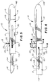
- Fig. 21 is a perspective view of the guarded scalpel of the present invention, showing the guard in the form of an inverted U-shaped channel telescopically mounted within the handle of the scalpel for sliding movement therein, the guard being shown in its advanced position substantially covering the blade.
- Fig. 22 is a further perspective view, corresponding substantially to that of Fig. 21, but showing the guard retracted within the handle to expose the blade.
- Fig. 23 is a longitudinal cross-sectional view of the preferred guarded scalpel, taken along the lines 23-23 of Fig. 21.
- Fig. 24 is an end view of the guarded scalpel of Fig. 23.
- Fig. 25 is a cross-sectional view of the guarded scalpel, taken along the lines 25-25 of Fig. 23, and drawn to an enlarged scale.
- the guarded scalpel 10 has a guard 11 for the blade 12.
- the blade 12 is conventional and is removably mounted on the scalpel 10 (as hereinafter described).
- the scalpel 10 may be passed from the nurse to the surgeon in an guarded position (Fig. 3A) to prevent the nurse from being cut. Thereafter, the surgeon may retract the guard 11 in a one-handed movement (Fig. 3B) to expose the blade 12. After making one or more incisions, the surgeon may advance the guard (Fig. 3C) --- again, in a one-handed movement and without taking his or her eyes away from the patient or the instrumentation in the O.R. --- and pass the scalpel 10 back to the nurse (Fig. 3D). The risk of getting cut has been substantially reduced, if not eliminated altogether.
- guarded scalpels 10 may be passed back and forth in the O.R. during a lengthy procedure on a patient.
- the guard 11 is substantially U-shaped and closely conforms to the outer contours of the scalpel 10.
- the guard 11 includes parallel side walls 11A and 11B, a bottom wall, and a top portion 16.
- the top portion 16 includes a pair of inturned flanges 17, respectively, defining a slot 19 therebetween. These inturned flanges 17 are received in longitudinal guide tracks 15 formed in the sides, respectively, in the body portion or handle 14 of the scalpel 10, thereby slidably mounting the guard 11 on the handle 14.
- a stop means is provided to limit the sliding movement of the guard 11.
- the side wall 11A of the guard 11 has a closed longitudinal slot 30 formed therein; and a pin 32 passes through the closed longitudinal slot 30 and is secured within a transverse bore 31 in the handle 14, thereby restricting the longitudinal sliding movement of the guard 11 and defining its alternate advanced and retracted positions, respectively.
- the pin 32 is a split sleeve as shown more clearly in Fig. 8.
- a two-position resiliently-biased manually-manipulatable detent means 13 is provided between the guard 11 and the handle 14 of the scalpel 10. This detent means 13, which is manually releasable, positively locks the guard 11 in its selected position and precludes inadvertent or accidental movement thereof.
- the preferred detent means 13 includes a resilient-biased detent member 22.
- the detent member 22 is carried by the handle 14 and is disposed substantially within the (vertical) longitudinai midplane or center plane thereof, as shown more clearly in Fig. 6, and about an axis which is substantially perpendicular to the longitudinal axis of the guard 11.
- the detent member 22 is backed up substantially by the material portion of the handle 14 --- the detent member 22 is not disposed laterally thereof --- and minimizes the extended outer contours of the guarded scalpel 10.
- the detent member 22 includes a stem 23A, an intermediate collar 23B, and an upwardly-projecting portion or button 23C.
- the handle 14 has a bore communicating with a counterbore 21B and a cross-cut, respectively.
- Stem 23A of the detent member 22 is slidably guided in the bore, so that the detent member 22 has a smooth inward movement without being cocked.
- a coil spring 24 is within the counterbore 21B and bears against the collar 23B, thereby constantly urging the detent member 22 outwardly (upwardly) of the handle 14; and the collar 23B is slidably received within the cross-cut.
- the button 23C passes through an opening 38 in a retaining plate 27, and the retaining plate 27 is secured to the handle 14 by a screw 29 received in a tapped recess 21A.
- a pair of longitudinally-spaced detent pockets 19A and 19B are formed in the inturned flanges 17 on the guard 11 to receive, alternately, the collar 23B on the detent member 22.
- the collar 23B clears its respective detent pocket 19A or 19B and allows the guard 11 to be slidably moved along the handle 14 and into its alternate position.
- the guard is advanced (forwardly) on the handle 14 to cover the blade 12 and prevent accidental contact with the blade 12 during transfer of the scalpel 10; and when the collar 23B is received in detent pocket 19A, the guard 11 is retracted (rearwardly) on the handle 14 to expose the blade 12 during an operating procedure.
- a cap 26 may be provided (as shown more clearly in Fig. 10).
- an alternate embodiment of the detent member 22 comprises a detent ball 25 resiliently biased by a spring 24.
- the spring 24 is in a blind bore 21B, and the detent ball 25 is slidably guided in a counterbore.
- the bottom wall of the guard 11 has a cut-out 18 extending upwardly into the respective side walls 11A and 11B of the guard 11.
- This cut-out 18 is intended to receive either the thumb or forefinger of the recipient and thereby facilitate manual movement of the guard 11.
- the surgeon or nurse
- the orientation of the scalpel 10 that is, whether the cutting edge of the blade 12 is pointed “up” or “down”
- Figs. 13A-D the blade 12 is "down".
- the surgeon grasps the scalpel 10, such that the surgeon's thumb is on the upwardly-projecting button 23C on the detent member 22, and the surgeon's forefinger is in the cut-out 18.
- the button 23C is depressed, and the guard 11 is moved rearwardly to expose the blade 12.
- the button 23C is again depressed by the surgeon's thumb while the surgeon's forefinger is in the cut-out 18 (Fig. 13C) and, thereafter, the guard 11 is moved forwardly (Fig. 13D) to cover the blade 11.
- Figs. 14A-D a similar sequence is followed. There, however, the cutting edge of the blade is "up”, and the surgeon's thumb is in the cut-out 18 while his or her forefinger is on the button 23C.
- the features and advantages of the above described scalpel are as follows: When the scalpel 10 is passed from the nurse to the surgeon (for example) the surgeon knows intuitively from the "feel" of the scalpel 10 that the guard 11 is "on", covering the blade 12, and that the edge on the blade 12 is either “up” or “down”. The surgeon may retract the guard 11, easily and conveniently, using only one hand and without taking his (or her) eyes away from the patient or the instrumentation in the operating room.
- the detent means is within the "meaty" portion of the handle 14, that is, within the (vertical) longitudinal center plane thereof, thereby taking maximum advantage of the handle material and, conversely, facilitating a strong detent action.
- This strong detent action between the guard 11 and the handle 14 provides not only a tactile indication, but also an auditory "click” that the guard 11 has been moved into its alternate desired position, that is, retracted to expose the blade 12 or advanced to cover the blade 12.
- the detented action is “solid” and prevents inadvertent or accidental movement of the guard 11 during a surgical procedure or in transferring the scalpel 10.
- a stop means between the guard 11 and the handle 14, including the closed slot 30 and the transverse pin 32, is independent of the detent means itself; this improves the reliability of the instrument.
- the guard 11 closely straddles the handle 14 and maintains the desired "slim line” appearance; and the added weight of the guard 11 is relatively insignificant and does not detract from the overall balance, feel and handling of the lightweight scalpel 10.
- the components of the overall assembly of the scalpel 10 may be manufactured conveniently and economically out of readily available materials, and the scalpel may be sterilized in an autoclave for repeated usage.
- the blade 12 has a closed slot 33 which fits over a laterally-extending longitudinal rib 34 formed on the forward end 14A of the handle 14, thereby removably mounting the blade 12 to the scalpel 10.
- the forward end 14A of the scalpel body 10 has a shoulder 35 substantially at right angles thereto.
- This shoulder 35 corresponds to an angled shoulder 36 on a conventional non-guarded scalpel S as shown in Fig. 17.
- the angled shoulder 36 cooperates with a conventional blade (not shown) having a rearward angled portion complementary to the angled shoulder 36.
- the improved blade 12 has a rearward shoulder or edge 38 which is substantially at right angles thereto (as shown more clearly in Fig. 16) and complementary to the right angle shoulder 35 on the scalpel 10.
- the blade 12 fits snugly against the shoulder 53 when the blade 12 is removably mounted on the scalpel 10.
- a blade 12 can be fitted to a conventional non-guarded scalpel S, if desired, as well as to the improved scalpel 101 of the present invention.
- the detent member 29' has an externally-tapered self-aligning portion 32', thereby piloting the detent member 29' into its respective detent pocket 42' and assuring a "solid" detent actin between the guard 11 and the handle 24', and thereby compensating for any misalignments or tolerance accumulations in the manufacture and assembly of the guarded surgical scalpel 10.
- the improved guarded surgical according to the present invention scalpel 100 includes a generally-tubular housing providing a handle 101 having a rectangular cross-section, as shown more clearly in Fig. 25.
- the handle 101 has a closed rearward end 102 and an open forward end 103 and, in this embodiment, is formed from two complementary members including an upper member 101A and a lower member 101B, respectively. These members 101A and 101B are joined together adhesively or by ultrasonic welding or by other suitable means.
- the lower member 101B has a central upstanding longitudinally-extending section constituting a cleat 104.
- This cleat 104 includes a forwardly-extending rib 105 upon which the conventional scalpel blade 106 is mounted.
- a guard 107 is telescopically mounted within the handle 101 for sliding or reciprocating movement therein between an advanced position in which the blade 106 is substantially covered or protected against inadvertent or accidental cuts or nicks (Fig. 21) and an alternate retracted position in which the blade 105 is exposed (Fig. 22) for use during a surgical procedure.
- the guard 107 comprises a substantially inverted U-shaped channel member having a top wall 108 and respective substantially-parallel legs or side walls 109 and 110, respectively, depending therefrom.
- the channel-shaped guard 107 is slidably mounted between the upper member 101A of the handle 101 and the cleat 104 of the lower member 101B.
- the guard 107 is manually retracted and advanced, alternately, by means of a-slide button 111 secured to the top wall 108 by a screw 112.
- the guard 107 has a two-position resiliently-biased detent means 113 with respect to the handle 101.
- This detent means 113 includes a detent ball 114 backed up by a spring 115 lodged in a blind bore 116 in the slide button 111 (Fig. 25).
- This detent ball 114 is carried by the slide button 111, rides in a closed slot 117 formed in the upper member 101A of the handle 101, and is received (alternately) in respective detent pockets 118 and 119 at the ends of the slot 117.
- the detent means 113 thereby defines the extent of the longitudinal sliding movement of the guard 107 within the handle 101 and, preferably, provides a relatively-loud audible "click" signaling to the user of the instrument that the guard 107 has been moved into its alternate position (either advanced or retracted). This detent action is positive, avoids accidental or inadvertent movement of the guard 107, yet it is convenient and easy to manually manipulate the telescopic sliding guard 107.
- the stop means 120 includes at least one pin 121 carried by the upper member 101A of the handle 101, transversely thereof, and received in respective closed longitudinal slots 122 and 123 formed in the downwardly-depending side walls 109 and 110, respectively, of the inverted channel-shaped guard 107.
- the pin 121 is also received in the central longitudinal section 104 of the lower member 101B of the handle 101, as shown more clearly in Fig. 25.
- the guarded scalpel 100 may be made of plastic (as shown) or metal, if desired, so that the guarded scalpel 100 may be either disposable or reusable.
- the guard 107 may be formed of a transparent plastic material, as shown in Figs. 21 and 25, so that the blade 106 is clearly visible at all times.
Landscapes
- Health & Medical Sciences (AREA)
- Life Sciences & Earth Sciences (AREA)
- Surgery (AREA)
- Molecular Biology (AREA)
- General Health & Medical Sciences (AREA)
- Biomedical Technology (AREA)
- Heart & Thoracic Surgery (AREA)
- Medical Informatics (AREA)
- Nuclear Medicine, Radiotherapy & Molecular Imaging (AREA)
- Animal Behavior & Ethology (AREA)
- Engineering & Computer Science (AREA)
- Public Health (AREA)
- Veterinary Medicine (AREA)
- Surgical Instruments (AREA)
- Materials For Medical Uses (AREA)
- Saccharide Compounds (AREA)
- Confectionery (AREA)
Claims (8)
- Geschütztes chirurgisches Skalpell (100) mit einem Griff (101) und einer Klinge (106) sowie einem daran befestigten Schutz (107), einer zwei Positionen einnehmenden, elastisch vorgespannten Rasteinrichtung (113) zwischen dem Schutz (107) und dem Griff (101), wodurch eine vorgeschobene Position des Schutzes (107), in der die Klinge (106) im wesentlichen bedeckt ist, und eine alternative zurückgezogene Position des Schutzes (107), in der die Klinge (106) frei liegt, abgegrenzt wird, sowie mit einer Lager-Führungseinrichtung zwischen dem Schutz (107) und dem Griff (101), die unabhängig von der Rasteinrichtung (113) ist und eine Anschlageinrichtung (120) schafft, die die gleitende Bewegung des Schutzes (107) begrenzt, dadurch gekennzeichnet, daß der Griff (101) im wesentlichen hohl und der Schutz (107) umgekehrt U-förmig ist und innerhalb des Griffs (101) teleskopartig montiert ist, um eine gleitende Bewegung darin ausführen zu können.
- Geschütztes chirurgische Skalpell nach Anspruch 1, bei dem die Anschlageinrichtung (120) einen Stift (121) aufweist, der durch den Griff (101) quer zu diesem getragen wird, und bei dem der Schutz (107) ein Paar von parallelen Seitenwänden (109, 110) umfaßt, die jeweils einen darin ausgebildeten und den Stift (121) aufnehmenden, längsverlaufenden Schlitz (122, 123) aufweisen.
- Geschütztes chirurgische Skalpell nach Anspruch 2, dadurch gekennzeichnet, daß die längsverlaufenden Schlitze (122, 123) an jedem Ende geschlossen sind, so daß die Lager-Führungseinrichtung eine Anschlageinrichtung (120) zum Begrenzen der alternativen vorgeschobenen und zurückgezogenen Positionen des Schutzes (107) in bezug auf den Griff (101) schafft, wobei die Anschlageinrichtung (120) unabhängig von der Rasteinrichtung (113) ist.
- Geschütztes chirurgische Skalpell (100) nach Anspruch 1, dadurch gekennzeichnet, daß die Rasteinrichtung (113) ein Rastelement (114) aufweist, das entweder von dem Griff (101) oder dem Schutz (107) getragen wird, wobei das entsprechend andere Teil, d.h. der Schutz (107) bzw. der Griff (101), einen längsverlaufenden Schlitz (117) aufweist, der das Rastelement (114) aufnimmt.
- Geschütztes chirurgische Skalpell (100) nach Anspruch 4, dadurch gekennzeichnet, daß der längsverlaufende Schlitz (117) ein Paar von voneinander beabstandeten Rast-Ausnehmungen (118, 119) zur alternativen Aufnahme des Rastelementes (114) aufweist.
- Geschütztes chirurgische Skalpell (100) nach Anspruch 5, gekennzeichnet durch einen Rastknopf (111), der über dem Griff (101) angeordnet ist und das Rastelement (114) aus einer entsprechenden Rastausnehmung (118, 119) löst.
- Geschütztes chirurgische Skalpell (100) nach Anspruch 6, dadurch gekennzeichnet, daß der das Rastelement (114) aufnehmende, längsverlaufende Schlitz (117) in der Oberseite (101A) des Griffes (101) ausgebildet ist.
- Geschütztes chirurgische Skalpell (100) nach Anspruch 1, dadurch gekennzeichnet, daß der Griff (101) ein unteres Element (101B) mit einem sich in Längsrichtung erstreckenden Abschnitt umfaßt, der eine Klampe (104) bildet, wobei die Klampe (104) mit einer Rippe (105) zur Montage der Klinge (106) daran versehen ist.
Applications Claiming Priority (2)
| Application Number | Priority Date | Filing Date | Title |
|---|---|---|---|
| US150843 | 1980-05-19 | ||
| US08/150,843 US5411512A (en) | 1992-01-24 | 1993-11-12 | Guarded surgical scalpel |
Publications (2)
| Publication Number | Publication Date |
|---|---|
| EP0653190A1 EP0653190A1 (de) | 1995-05-17 |
| EP0653190B1 true EP0653190B1 (de) | 1997-03-05 |
Family
ID=22536225
Family Applications (1)
| Application Number | Title | Priority Date | Filing Date |
|---|---|---|---|
| EP94870174A Expired - Lifetime EP0653190B1 (de) | 1993-11-12 | 1994-11-09 | Geschütztes Skalpell |
Country Status (8)
| Country | Link |
|---|---|
| US (2) | US5411512A (de) |
| EP (1) | EP0653190B1 (de) |
| JP (1) | JPH0856952A (de) |
| AT (1) | ATE149320T1 (de) |
| AU (1) | AU7776494A (de) |
| BR (1) | BR9404431A (de) |
| CA (1) | CA2135436A1 (de) |
| DE (1) | DE69401896D1 (de) |
Cited By (2)
| Publication number | Priority date | Publication date | Assignee | Title |
|---|---|---|---|---|
| US7909840B2 (en) | 2004-10-20 | 2011-03-22 | Beaver-Visitec International (Us), Inc. | Surgical knife safety handle having user operable lock |
| US8464430B2 (en) | 2008-02-07 | 2013-06-18 | Beaver-Visitec International (Us), Inc. | Retractable safety knife |
Families Citing this family (63)
| Publication number | Priority date | Publication date | Assignee | Title |
|---|---|---|---|---|
| USRE42507E1 (en) | 1993-12-08 | 2011-06-28 | Aspen Surgical Products, Inc. | Surgical scalpel |
| AUPM456494A0 (en) * | 1994-03-17 | 1994-04-14 | Noble House Group Pty Ltd | Scalpel |
| US5727682A (en) * | 1994-05-18 | 1998-03-17 | Bloom & Kreten | Low-cost safe blade package for surgical purposes |
| US5620454A (en) * | 1994-10-25 | 1997-04-15 | Becton, Dickinson And Company | Guarded surgical scalpel |
| US5827309A (en) * | 1994-10-25 | 1998-10-27 | Becton, Dickinson And Company | Guarded surgical scalpel with scalpel blade remover |
| US5683407A (en) * | 1995-10-19 | 1997-11-04 | Becton, Dickinson And Company | Cleanable guarded surgical scalpel with scalpel blade remover |
| US5908432A (en) * | 1998-03-27 | 1999-06-01 | Pan; Huai C. | Scalpel with retractable blade |
| US6530903B2 (en) | 2000-02-24 | 2003-03-11 | Xiping Wang | Safety syringe |
| US6478800B1 (en) | 2000-05-08 | 2002-11-12 | Depuy Acromed, Inc. | Medical installation tool |
| US6626925B2 (en) | 2001-03-29 | 2003-09-30 | Becton Dickinson And Company | Shielded surgical scalpel |
| GB2383952B (en) * | 2002-01-09 | 2005-01-19 | Fulcrum | Surgical Tool |
| AU2003223429A1 (en) * | 2002-04-05 | 2003-10-27 | University Of Rochester | Cryogenically cooled phased array rf receiver coil for magnetic resonance imaging |
| CN1382423A (zh) * | 2002-05-27 | 2002-12-04 | 钱倚天 | 具有保护滑套的手术刀 |
| US7509742B2 (en) * | 2002-11-19 | 2009-03-31 | Earl & Kimberly Votolato, Trustees Of The Votolato Living Trust | Safety cutting apparatus |
| USD502542S1 (en) | 2002-12-27 | 2005-03-01 | Becton Dickinson And Company | Handle |
| USD482788S1 (en) | 2002-12-27 | 2003-11-25 | Becton Dickinson And Company | Blade carrier |
| USD490154S1 (en) | 2002-12-27 | 2004-05-18 | Becton, Dickinson And Company | Handle |
| USD489457S1 (en) | 2002-12-27 | 2004-05-04 | Becton Dickinson And Company | Handle |
| USD483124S1 (en) | 2002-12-27 | 2003-12-02 | Becton Dickinson And Company | Handle |
| USD483123S1 (en) | 2002-12-27 | 2003-12-02 | Becton Dickinson And Company | Blade carrier |
| USD490153S1 (en) | 2002-12-27 | 2004-05-18 | Becton Dickinson And Company | Blade carrier |
| USD486232S1 (en) | 2002-12-27 | 2004-02-03 | Becton Dickinson And Company | Handle |
| USD482449S1 (en) | 2002-12-27 | 2003-11-18 | Becton Dickinson And Company | Handle |
| USD482122S1 (en) | 2002-12-27 | 2003-11-11 | Becton Dickinson And Company | Handle |
| USD481129S1 (en) | 2003-01-29 | 2003-10-21 | Becton Dickinson And Company | Blade holder |
| USD496730S1 (en) | 2003-03-17 | 2004-09-28 | Becton, Dickinson & Company | Surgical knife safety handle |
| US7022128B2 (en) | 2003-04-22 | 2006-04-04 | Becton, Dickinson And Company | Surgical knife safety handle |
| TW200509851A (en) * | 2003-04-22 | 2005-03-16 | Becton Dickinson Co | Surgical knife safety handle |
| US7153317B2 (en) * | 2003-05-30 | 2006-12-26 | Ribbel International Limited | Disposable guarded surgical scalpel |
| US20050065541A1 (en) * | 2003-09-24 | 2005-03-24 | Alb Associates, Llc | Guarded surgical scalpel with blade stripper lock to prevent accidental or inadvertent ejection of the blade |
| US7172611B2 (en) * | 2004-03-22 | 2007-02-06 | Becton, Dickinson And Company | Surgical scalpel assembly |
| US7308896B2 (en) * | 2004-06-22 | 2007-12-18 | Emergency Medical Devices, Inc. | Combination tracheal hook and scalpel device |
| EP1809188A4 (de) | 2004-10-22 | 2010-12-01 | Canica Design Inc | Sicherheitsskalpell |
| US7036660B1 (en) | 2004-11-29 | 2006-05-02 | Michael R. Abidin | Surgical blade package |
| US8114103B2 (en) * | 2005-09-14 | 2012-02-14 | James Edwin Rasco | Scalpel blade protector |
| US7159713B1 (en) | 2005-11-01 | 2007-01-09 | Georgene Austria | Sharp blade protection device |
| US8377072B2 (en) | 2006-02-06 | 2013-02-19 | Depuy Spine, Inc. | Medical device installation tool |
| AU2007218706B2 (en) * | 2006-02-27 | 2012-04-19 | Feather Safety Razor Co., Ltd. | Edged tool |
| USD561898S1 (en) | 2006-02-28 | 2008-02-12 | Feather Safety Razor Co., Ltd. | Blade guard for a surgical knife |
| US7810241B2 (en) * | 2006-05-23 | 2010-10-12 | Pooler Jason C | Shielded scalpel |
| USD571010S1 (en) | 2006-10-17 | 2008-06-10 | Becton, Dickinson And Company | Surgical knife safety handle |
| USD568475S1 (en) * | 2007-03-21 | 2008-05-06 | Sandel Medical Industries, Llc | Scalpel |
| US20100268258A1 (en) * | 2007-12-11 | 2010-10-21 | Maxwell Timothy J | Safety scalpel |
| US20100089405A1 (en) * | 2008-04-04 | 2010-04-15 | Tactical Medical Solutions, Inc. | Combination tracheal hook and surgical blade |
| US8205340B2 (en) * | 2008-07-26 | 2012-06-26 | Georgene Austria | Safety scalpel with blade retention |
| US8256330B2 (en) * | 2008-11-20 | 2012-09-04 | Alcon Research, Ltd. | Guarded surgical knife handle |
| US8256331B2 (en) * | 2008-11-20 | 2012-09-04 | Alcon Research, Ltd. | Guarded surgical knife handle |
| US20100217297A1 (en) * | 2009-02-26 | 2010-08-26 | Anita Nevyas-Wallace | Surgical Knife Providing Enhanced Blade Visualization |
| US20100325899A1 (en) * | 2009-06-24 | 2010-12-30 | Seber Brett P | Retractable utility knife |
| CZ306374B6 (cs) * | 2009-08-18 | 2016-12-28 | Výzkumný ústav živočišné výroby v. v. i. | Skalpel s nastavitelnou hloubkou řezu |
| US8875405B2 (en) * | 2010-04-09 | 2014-11-04 | Oasis Medical, Inc. | Micro surgical knife with safety feature |
| WO2012002910A1 (en) * | 2010-06-28 | 2012-01-05 | Medipurpose Pte Ltd | Safety scalpel |
| US8834500B2 (en) * | 2011-03-04 | 2014-09-16 | Vascular Solutions, Inc. | Hand-held vein removal device |
| US9622773B2 (en) | 2012-03-19 | 2017-04-18 | Aspen Surgical Products, Inc. | Side activated safety scalpel for left and right hand users with blade removal system |
| CA2870783C (en) * | 2012-04-26 | 2015-03-17 | Ryan KANIGAN | Safety scalpel |
| US20160095614A1 (en) | 2014-10-03 | 2016-04-07 | Aspen Surgical Products, Inc. | Sharps blade applicator and storage device |
| US10123815B2 (en) | 2015-02-13 | 2018-11-13 | Precision Engineered Products, Llc | Surgical knife |
| USD813390S1 (en) | 2016-01-15 | 2018-03-20 | Aspen Surgical Products, Inc. | Surgical scalpel blade attachment |
| US20170265882A1 (en) | 2016-03-21 | 2017-09-21 | Aspen Surgical Products, Inc. | Safety scalpel handle |
| US10207414B2 (en) * | 2016-11-17 | 2019-02-19 | Goodrich Corporation | Safety knife with retractable sheath |
| US10716592B2 (en) | 2017-09-05 | 2020-07-21 | Aspen Surgical Products Inc. | Scalpel blade loader |
| US12290256B1 (en) * | 2022-06-02 | 2025-05-06 | Lonnie J. Ginn | Suture cutter device and method of use |
| WO2024249259A1 (en) * | 2023-05-26 | 2024-12-05 | Gwbn, Llc | Cutting device and related systems and methods |
Family Cites Families (31)
| Publication number | Priority date | Publication date | Assignee | Title |
|---|---|---|---|---|
| US1195169A (en) * | 1916-08-22 | Masvin e | ||
| US1914153A (en) * | 1931-09-08 | 1933-06-13 | John J Ogden | Surgical knife |
| US2885780A (en) * | 1957-12-03 | 1959-05-12 | Floyd A Campbell | Marking tool |
| US3706106A (en) * | 1971-01-18 | 1972-12-19 | Norbert Leopoldi | Surgical knife |
| US3943627A (en) * | 1973-11-28 | 1976-03-16 | Stanley Jr Conrad | Front loading utility knife |
| US3906626A (en) * | 1974-04-19 | 1975-09-23 | Becton Dickinson Co | Disposable surgical scalpel |
| US3905101A (en) * | 1974-04-19 | 1975-09-16 | Becton Dickinson Co | Disposable surgical scalpel |
| US4091537A (en) * | 1977-04-26 | 1978-05-30 | Stevenson Machine Shop | Safety utility knife |
| US4393587A (en) * | 1981-04-23 | 1983-07-19 | Kloosterman William A | Spring shielded safety knife |
| US4414974A (en) * | 1981-06-09 | 1983-11-15 | General Conveyors Limited | Microsurgical knife |
| US4516575A (en) * | 1982-06-03 | 1985-05-14 | Coopervision, Inc. | Surgical scalpel |
| US4491132A (en) * | 1982-08-06 | 1985-01-01 | Zimmer, Inc. | Sheath and retractable surgical tool combination |
| US4499898A (en) * | 1982-08-23 | 1985-02-19 | Koi Associates | Surgical knife with controllably extendable blade and gauge therefor |
| US4538356A (en) * | 1982-08-23 | 1985-09-03 | Koi Associates, Inc. | Surgical knife with controllably extendable blade and gauge therefor |
| US4576164A (en) * | 1983-11-14 | 1986-03-18 | Richeson W George | Knife with locking shroud |
| US4523379A (en) * | 1984-05-02 | 1985-06-18 | Tekna | Knife with retractable sheath |
| US4757612A (en) * | 1985-03-21 | 1988-07-19 | Preposreve S.A.R.L. | Fixed-blade knife with retractable blade cover |
| IL75096A (en) * | 1985-05-05 | 1989-05-15 | Porat Michael | Scalpel |
| US4630378A (en) * | 1985-06-13 | 1986-12-23 | Pilling Co. | Gauge for extensible-blade surgical knife |
| US4662075A (en) * | 1985-08-22 | 1987-05-05 | Magnum Diamond Reclamation, Inc. | Apparatus and method for setting knife blade depth |
| GB2187989B (en) * | 1986-03-18 | 1989-11-15 | Sabre Int Prod Ltd | Knives |
| US4815218A (en) * | 1986-06-13 | 1989-03-28 | Cilco, Inc. | Gauge for calibrating surgical scalpel |
| US4735202A (en) * | 1986-10-06 | 1988-04-05 | Alcon Laboratories, Inc. | Microsurgical knife with locking blade guard |
| DE3722899A1 (de) * | 1987-07-08 | 1989-01-19 | Peters Tim | Skalpell |
| US5071426A (en) * | 1989-04-06 | 1991-12-10 | Stuart Dolgin | Surgical scalpel with retractable blade guard |
| US4985034A (en) * | 1989-06-01 | 1991-01-15 | Board Of Regents, The University Of Texas System | Safety surgical blade, handle and shield |
| US5035703A (en) * | 1990-05-09 | 1991-07-30 | Baskas Morris J | Disposable syringe needle and scalpel holder |
| US5015252A (en) * | 1990-08-13 | 1991-05-14 | Jones Mark W | Surgical forceps with suture cutters |
| US5250063A (en) * | 1992-01-24 | 1993-10-05 | Leonard Bloom | Surgical scalpel with retractable guard |
| US5207696A (en) * | 1992-04-30 | 1993-05-04 | Medical Sterile Products, Inc. | Surgical scalpel |
| US5344424A (en) * | 1993-03-12 | 1994-09-06 | Roberts Philip L | Selectively retractable, disposable surgical knife |
-
1993
- 1993-11-12 US US08/150,843 patent/US5411512A/en not_active Expired - Lifetime
-
1994
- 1994-11-09 CA CA002135436A patent/CA2135436A1/en not_active Abandoned
- 1994-11-09 AT AT94870174T patent/ATE149320T1/de not_active IP Right Cessation
- 1994-11-09 EP EP94870174A patent/EP0653190B1/de not_active Expired - Lifetime
- 1994-11-09 DE DE69401896T patent/DE69401896D1/de not_active Expired - Lifetime
- 1994-11-10 JP JP6312317A patent/JPH0856952A/ja active Pending
- 1994-11-10 AU AU77764/94A patent/AU7776494A/en not_active Abandoned
- 1994-11-11 BR BR9404431A patent/BR9404431A/pt active Search and Examination
-
1995
- 1995-04-26 US US08/429,194 patent/US5569281A/en not_active Expired - Lifetime
Cited By (5)
| Publication number | Priority date | Publication date | Assignee | Title |
|---|---|---|---|---|
| US7909840B2 (en) | 2004-10-20 | 2011-03-22 | Beaver-Visitec International (Us), Inc. | Surgical knife safety handle having user operable lock |
| US8814893B2 (en) | 2004-10-20 | 2014-08-26 | Beaver-Visitec International (Us), Inc. | Surgical knife safety handle having user operable lock |
| US9480495B2 (en) | 2004-10-20 | 2016-11-01 | Beaver-Visitec International (Us), Inc. | Surgical knife safety handle having user operable lock |
| US8464430B2 (en) | 2008-02-07 | 2013-06-18 | Beaver-Visitec International (Us), Inc. | Retractable safety knife |
| US9044265B2 (en) | 2008-02-07 | 2015-06-02 | Beaver-Visitec International (Us), Inc. | Retractable safety knife |
Also Published As
| Publication number | Publication date |
|---|---|
| CA2135436A1 (en) | 1995-05-13 |
| US5569281A (en) | 1996-10-29 |
| EP0653190A1 (de) | 1995-05-17 |
| DE69401896D1 (de) | 1997-04-10 |
| US5411512A (en) | 1995-05-02 |
| AU7776494A (en) | 1995-05-18 |
| ATE149320T1 (de) | 1997-03-15 |
| BR9404431A (pt) | 1995-06-20 |
| JPH0856952A (ja) | 1996-03-05 |
Similar Documents
| Publication | Publication Date | Title |
|---|---|---|
| US5569281A (en) | Guarded surgical scalpel | |
| US5275606A (en) | Guarded scalpel for surgical use | |
| US5496340A (en) | Combination guarded surgical scalpel and blade stripper | |
| US5527329A (en) | Surgical scalpel | |
| US5620454A (en) | Guarded surgical scalpel | |
| US5342379A (en) | Safety scalpel | |
| JP4230775B2 (ja) | シールド付外科用メス | |
| US8819943B2 (en) | Safety scalpel | |
| US5330492A (en) | Safety scalpel | |
| US6022364A (en) | Disposable surgical safety scalpel | |
| US7207999B2 (en) | Safety scalpel | |
| US6053929A (en) | Surgical scalpel | |
| US8764781B2 (en) | Guarded surgical knife handle | |
| EP0948937A2 (de) | Chirurgisches Skalpell | |
| US20090192538A1 (en) | Safety scalpel handle | |
| WO1990011725A1 (en) | Surgical scalpel with retractable blade guard | |
| USRE42507E1 (en) | Surgical scalpel | |
| US20170071619A1 (en) | Safety scalpel |
Legal Events
| Date | Code | Title | Description |
|---|---|---|---|
| PUAI | Public reference made under article 153(3) epc to a published international application that has entered the european phase |
Free format text: ORIGINAL CODE: 0009012 |
|
| AK | Designated contracting states |
Kind code of ref document: A1 Designated state(s): AT BE CH DE DK ES FR GB GR IE IT LI LU MC NL PT SE |
|
| RAX | Requested extension states of the european patent have changed |
Free format text: LT PAYMENT 941118;SI PAYMENT 941118 |
|
| 17P | Request for examination filed |
Effective date: 19950811 |
|
| 17Q | First examination report despatched |
Effective date: 19960209 |
|
| GRAG | Despatch of communication of intention to grant |
Free format text: ORIGINAL CODE: EPIDOS AGRA |
|
| GRAH | Despatch of communication of intention to grant a patent |
Free format text: ORIGINAL CODE: EPIDOS IGRA |
|
| GRAH | Despatch of communication of intention to grant a patent |
Free format text: ORIGINAL CODE: EPIDOS IGRA |
|
| GRAA | (expected) grant |
Free format text: ORIGINAL CODE: 0009210 |
|
| AK | Designated contracting states |
Kind code of ref document: B1 Designated state(s): AT BE CH DE DK ES FR GB GR IE IT LI LU MC NL PT SE |
|
| AX | Request for extension of the european patent |
Free format text: LT PAYMENT 941118;SI PAYMENT 941118 |
|
| PG25 | Lapsed in a contracting state [announced via postgrant information from national office to epo] |
Ref country code: NL Free format text: LAPSE BECAUSE OF FAILURE TO SUBMIT A TRANSLATION OF THE DESCRIPTION OR TO PAY THE FEE WITHIN THE PRESCRIBED TIME-LIMIT Effective date: 19970305 Ref country code: LI Effective date: 19970305 Ref country code: IT Free format text: LAPSE BECAUSE OF FAILURE TO SUBMIT A TRANSLATION OF THE DESCRIPTION OR TO PAY THE FEE WITHIN THE PRE;WARNING: LAPSES OF ITALIAN PATENTS WITH EFFECTIVE DATE BEFORE 2007 MAY HAVE OCCURRED AT ANY TIME BEFORE 2007. THE CORRECT EFFECTIVE DATE MAY BE DIFFERENT FROM THE ONE RECORDED.SCRIBED TIME-LIMIT Effective date: 19970305 Ref country code: GR Free format text: LAPSE BECAUSE OF FAILURE TO SUBMIT A TRANSLATION OF THE DESCRIPTION OR TO PAY THE FEE WITHIN THE PRESCRIBED TIME-LIMIT Effective date: 19970305 Ref country code: FR Effective date: 19970305 Ref country code: ES Free format text: THE PATENT HAS BEEN ANNULLED BY A DECISION OF A NATIONAL AUTHORITY Effective date: 19970305 Ref country code: DK Effective date: 19970305 Ref country code: CH Effective date: 19970305 Ref country code: BE Effective date: 19970305 Ref country code: AT Effective date: 19970305 |
|
| REF | Corresponds to: |
Ref document number: 149320 Country of ref document: AT Date of ref document: 19970315 Kind code of ref document: T |
|
| REG | Reference to a national code |
Ref country code: CH Ref legal event code: EP |
|
| REF | Corresponds to: |
Ref document number: 69401896 Country of ref document: DE Date of ref document: 19970410 |
|
| REG | Reference to a national code |
Ref country code: IE Ref legal event code: FG4D Free format text: 72402 |
|
| PG25 | Lapsed in a contracting state [announced via postgrant information from national office to epo] |
Ref country code: SE Effective date: 19970605 Ref country code: PT Effective date: 19970605 |
|
| PG25 | Lapsed in a contracting state [announced via postgrant information from national office to epo] |
Ref country code: DE Effective date: 19970606 |
|
| EN | Fr: translation not filed | ||
| NLV1 | Nl: lapsed or annulled due to failure to fulfill the requirements of art. 29p and 29m of the patents act | ||
| REG | Reference to a national code |
Ref country code: CH Ref legal event code: PL |
|
| PG25 | Lapsed in a contracting state [announced via postgrant information from national office to epo] |
Ref country code: LU Free format text: LAPSE BECAUSE OF NON-PAYMENT OF DUE FEES Effective date: 19971109 Ref country code: IE Free format text: LAPSE BECAUSE OF NON-PAYMENT OF DUE FEES Effective date: 19971109 |
|
| PLBE | No opposition filed within time limit |
Free format text: ORIGINAL CODE: 0009261 |
|
| STAA | Information on the status of an ep patent application or granted ep patent |
Free format text: STATUS: NO OPPOSITION FILED WITHIN TIME LIMIT |
|
| 26N | No opposition filed | ||
| PG25 | Lapsed in a contracting state [announced via postgrant information from national office to epo] |
Ref country code: MC Free format text: LAPSE BECAUSE OF NON-PAYMENT OF DUE FEES Effective date: 19980531 |
|
| PG25 | Lapsed in a contracting state [announced via postgrant information from national office to epo] |
Ref country code: GB Free format text: LAPSE BECAUSE OF NON-PAYMENT OF DUE FEES Effective date: 19981109 |
|
| GBPC | Gb: european patent ceased through non-payment of renewal fee |
Effective date: 19981109 |