EP0653196A1 - Ventil und innendrucksteuervorrichtung für Ostomiebeutel - Google Patents
Ventil und innendrucksteuervorrichtung für Ostomiebeutel Download PDFInfo
- Publication number
- EP0653196A1 EP0653196A1 EP94402501A EP94402501A EP0653196A1 EP 0653196 A1 EP0653196 A1 EP 0653196A1 EP 94402501 A EP94402501 A EP 94402501A EP 94402501 A EP94402501 A EP 94402501A EP 0653196 A1 EP0653196 A1 EP 0653196A1
- Authority
- EP
- European Patent Office
- Prior art keywords
- cover
- degassing device
- housing
- valve
- opening
- Prior art date
- Legal status (The legal status is an assumption and is not a legal conclusion. Google has not performed a legal analysis and makes no representation as to the accuracy of the status listed.)
- Granted
Links
- 238000013022 venting Methods 0.000 title abstract 2
- 238000007872 degassing Methods 0.000 claims description 32
- 239000007789 gas Substances 0.000 claims description 21
- 239000000463 material Substances 0.000 claims description 13
- 239000004033 plastic Substances 0.000 claims description 5
- 229920003023 plastic Polymers 0.000 claims description 5
- 238000001746 injection moulding Methods 0.000 claims description 2
- 238000004519 manufacturing process Methods 0.000 description 5
- 238000006073 displacement reaction Methods 0.000 description 4
- 210000005069 ears Anatomy 0.000 description 3
- 230000029142 excretion Effects 0.000 description 3
- 230000000968 intestinal effect Effects 0.000 description 3
- 239000007788 liquid Substances 0.000 description 3
- 238000000465 moulding Methods 0.000 description 3
- 239000007787 solid Substances 0.000 description 3
- OKTJSMMVPCPJKN-UHFFFAOYSA-N Carbon Chemical compound [C] OKTJSMMVPCPJKN-UHFFFAOYSA-N 0.000 description 2
- 230000007423 decrease Effects 0.000 description 2
- 230000000694 effects Effects 0.000 description 2
- 238000002347 injection Methods 0.000 description 2
- 239000007924 injection Substances 0.000 description 2
- 235000019645 odor Nutrition 0.000 description 2
- 238000007789 sealing Methods 0.000 description 2
- 238000011477 surgical intervention Methods 0.000 description 2
- 239000004952 Polyamide Substances 0.000 description 1
- 239000004698 Polyethylene Substances 0.000 description 1
- 240000008042 Zea mays Species 0.000 description 1
- 229920000122 acrylonitrile butadiene styrene Polymers 0.000 description 1
- 239000004676 acrylonitrile butadiene styrene Substances 0.000 description 1
- 239000000853 adhesive Substances 0.000 description 1
- 238000004026 adhesive bonding Methods 0.000 description 1
- 230000001070 adhesive effect Effects 0.000 description 1
- 239000011324 bead Substances 0.000 description 1
- 210000003323 beak Anatomy 0.000 description 1
- 230000000295 complement effect Effects 0.000 description 1
- 239000002781 deodorant agent Substances 0.000 description 1
- 229940082150 encore Drugs 0.000 description 1
- 239000006260 foam Substances 0.000 description 1
- 238000007455 ileostomy Methods 0.000 description 1
- 230000007257 malfunction Effects 0.000 description 1
- 230000002093 peripheral effect Effects 0.000 description 1
- 229920002647 polyamide Polymers 0.000 description 1
- -1 polyethylene Polymers 0.000 description 1
- 229920000573 polyethylene Polymers 0.000 description 1
- 230000000630 rising effect Effects 0.000 description 1
- 239000000758 substrate Substances 0.000 description 1
- 230000007704 transition Effects 0.000 description 1
Images




Classifications
-
- A—HUMAN NECESSITIES
- A61—MEDICAL OR VETERINARY SCIENCE; HYGIENE
- A61F—FILTERS IMPLANTABLE INTO BLOOD VESSELS; PROSTHESES; DEVICES PROVIDING PATENCY TO, OR PREVENTING COLLAPSING OF, TUBULAR STRUCTURES OF THE BODY, e.g. STENTS; ORTHOPAEDIC, NURSING OR CONTRACEPTIVE DEVICES; FOMENTATION; TREATMENT OR PROTECTION OF EYES OR EARS; BANDAGES, DRESSINGS OR ABSORBENT PADS; FIRST-AID KITS
- A61F5/00—Orthopaedic methods or devices for non-surgical treatment of bones or joints; Nursing devices ; Anti-rape devices
- A61F5/44—Devices worn by the patient for reception of urine, faeces, catamenial or other discharge; Colostomy devices
- A61F5/441—Devices worn by the patient for reception of urine, faeces, catamenial or other discharge; Colostomy devices having venting or deodorant means, e.g. filters ; having antiseptic means, e.g. bacterial barriers
-
- A—HUMAN NECESSITIES
- A61—MEDICAL OR VETERINARY SCIENCE; HYGIENE
- A61F—FILTERS IMPLANTABLE INTO BLOOD VESSELS; PROSTHESES; DEVICES PROVIDING PATENCY TO, OR PREVENTING COLLAPSING OF, TUBULAR STRUCTURES OF THE BODY, e.g. STENTS; ORTHOPAEDIC, NURSING OR CONTRACEPTIVE DEVICES; FOMENTATION; TREATMENT OR PROTECTION OF EYES OR EARS; BANDAGES, DRESSINGS OR ABSORBENT PADS; FIRST-AID KITS
- A61F5/00—Orthopaedic methods or devices for non-surgical treatment of bones or joints; Nursing devices ; Anti-rape devices
- A61F5/44—Devices worn by the patient for reception of urine, faeces, catamenial or other discharge; Colostomy devices
- A61F2005/4415—Devices worn by the patient for reception of urine, faeces, catamenial or other discharge; Colostomy devices venting by manual operation
Definitions
- the invention relates to a device for degassing and controlling the internal pressure of an ostomy collection bag and a bag provided with such a device.
- ostomy collection bags provided with degassing devices which allow both the evacuation of intestinal gases having penetrated in the pocket and maintaining in the latter a residual pressure value which prevents the sheets or films constituting the pocket from sticking to each other, thus preventing satisfactory collection of solid excretions or liquids.
- the device according to Patent Application FR 2 514 636 which comprises a valve body provided with two facing holes, one communicating with the inside of the pocket and surrounded by a seat valve, and the other communicating with the outside.
- valve shutter element in the form of a disc provided, around its periphery, with a certain number of elastic tabs which bear against the internal wall of the body. valve and press the valve member against the vent seat.
- an object of the invention to provide a device for degassing and controlling the internal pressure of a collection bag for an ostomy which makes it possible to solve the problem posed.
- an object of the invention to provide such a device, the use of which is simple and, therefore, can be used by all patients who have undergone a surgical intervention such as a colostomy or an ileostomy.
- an object of the invention to provide a collection bag for ostomy with which a device as defined above can be easily associated.
- a degassing device in particular for an ostomy bag, constituted by an essentially flat housing comprising a bottom having an internal face to the housing and an external face to the housing, adapted to be fixed by said external face on an exposed face of said pocket and provided with an opening communicating with said pocket, as well as a valve of the type closed at rest, said valve being formed by a closure member adapted to be applied on said opening of said bottom on the side of said internal face and in one piece with elastic means for pushing said member against said bottom with a predetermined restoring force, characterized in that the housing further comprises a removable cover adapted to close said bottom and in that the valve is integral with said lid.
- Assembly can therefore be carried out at the factory, for example by simply fitting the cover onto the bottom of the housing. It can also be performed by the user himself. The simplification or the absence of assembly at the factory results in a gain on the production costs all the more remarkable as the number of devices manufactured is important.
- the elastic means consist of at least one elastically deformable flat extending between said cover and said member. closing.
- a flat is easily obtained by manufacturing the bottom and the cover in the form of a blank in one piece, preferably by injection molding of a plastic material, bridges of material connecting in the blank said bottom and said cover so that the distance between said cover and said closure member is greater than the distance between said bottom and said cover in the final housing obtained by breaking said bridges of material and closing said bottom with said cover.
- a filter comprising a central hole is housed in said housing so that it is pinched between said valve and said bottom, its hole coming in the extension of said opening of said bottom. If necessary, the user himself places the filter in the vent. He can do it while he is carrying the pocket. This results in great flexibility of use.
- the assembly formed by said cover and said closure member is shaped to allow manual actuation of said valve.
- said housing is cylindrical and in that said cover is secured to said bottom so that it can be moved relative to said bottom by means of manual actuation in a rotational movement around the 'axis (A) of the housing.
- the cover is fixed on the bottom by interlocking and the manual actuation means consist of a radially projecting ear on the cover.
- said closure member is integral with at least one radial finger adapted to circulate, when said manual actuation means are actuated, in a guide of said bottom extending circumferentially and of shape such that said finger may, depending on its position in said guide, be free or be lifted against said elastic means along a ramp of the guide.
- said closure member consists of a needle, the cover also comprising at least one boss while said bottom comprises at least one helical ramp on which said boss is adapted to flow between a low position and a high position when the cover is turned relative to said bottom so that, in the low position, said needle is returned by the elastic means to close said opening while, in the high position, said needle is pushed out of the opening at the against said elastic means.
- said bosses are integral with a stud which carries said needle at its end, the free ends of said bosses being set back relative to said needle so that said needle enters said opening when said bosses are in the low position.
- the rotation of the cover results in an axial displacement of the needle which results in the opening of the valve.
- said housing preferably comprises an interior space adapted to receive a filter and limited by a cylindrical wall comprising axial recesses communicating with windows above the cover so that the gases can escape despite the presence a filter inside the housing. It is interesting that the bottom then has an internal relief adapted to pinch the filter so that the gases are forced to pass through the filter to escape through the recesses and the windows.
- the cover is fixed on the bottom by a bayonet fitting.
- said bottom and said cover preferably have edges adapted to collaborate so that once said bottom and said cover fitted, the edges cooperate to prevent them from separating, said edges extending over a sector of approximately 90 ° and being arranged diametrically opposite on the cover and on the bottom. Then, the cover can be inserted inside the bottom, the edges of the cover projecting outwards while the edges of the bottom project inwards.
- At least one ledge extends from preferably in an axial stop column adapted to prevent the bottom and cover from turning beyond a certain value and that the bosses consequently leave said ramp.
- the invention also relates to a collection bag comprising a degassing and internal pressure control device as described above.
- FIG. 1 to 7 A first embodiment of the device according to the invention, 10, for degassing and controlling the internal pressure of a collection bag for ostomy P is shown in Figures 1 to 7. It is intended to be fixed on the face exposed from the pocket which, of the disposable or drainable type, is generally constituted by two sheets or films of plastic material impermeable to odors, f 1, f 2, welded together on their periphery s . In a manner known per se, one of the films f 1, f 2 has an opening O, suitable for being placed in communication with the stoma when the pocket is secured to the patient's body, either by a connection system, or using an adhesive pad, either by a belt or, again, by a combination of these various means.
- Pocket P which collects solid or liquid excretions, collects also the intestinal gases which must be evacuated to prevent the bag from increasing excessively in volume. A certain residual pressure must however be maintained in the pocket to overcome the drawback which would result from the approximation and possible bonding of the two films f 1, f 2 to one another and which would prevent entry into the pocket, through the opening O, of solid or liquid excretions to be collected.
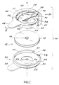
- the device according to the invention comprises an essentially flat box 11 (typical thickness 5 mm), FIG. 2, in which can be housed a filter 12 absorbing odors and produced from a porous substrate, such as foam, a woven or non-woven material, impregnated with activated carbon or another deodorant and which is shaped according to a thin disc covered on each of its faces with a gas-impermeable film, 13 and 14, respectively, the assembly having in its center a hole 15.
- a filter 12 absorbing odors and produced from a porous substrate, such as foam, a woven or non-woven material, impregnated with activated carbon or another deodorant and which is shaped according to a thin disc covered on each of its faces with a gas-impermeable film, 13 and 14, respectively, the assembly having in its center a hole 15.
- the housing 11 results from the assembly between them of a bottom 20 and a cover 21 advantageously made by molding, preferably by injection, of an elastically deformable plastic material such as polyethylene, polyamide, ABS, etc. etc., the bottom and the cover being connected to each other by a thin bead of material as long as they are not paired.
- the housing 11 has a generally cylindrical shape with axis A (with a diameter of the order of 30 mm) and the surfaces of its elements which are inside the housing will be said to be internal, while the others will be said to be external, in contrast.
- the bottom 20 which is intended to be fixed on the exposed face of the pocket, for example by an annular weld S or by gluing, comprises a flat part 22, with circular outline, pierced in its center with an opening 23 which is surrounded, on the internal face 24 of the bottom by a counterbore circular 25 and, on the external face 26, by a frustoconical counterbore 27, FIG. 7.
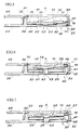
- From the part 22 is integral a wall 30, with cylindrical internal surface 31, of axis A and with frustoconical external surface 32 ( Figures 5 to 7 ) in order to provide a flange 33 for hooking by fitting the housing 21.
- a radial lug 35 protrudes in the plane of the part 22, outside the latter, while the wall 30 has a recess or guide 36, diametrically opposite the ear 35, and which provides at one of its ends a beak or hook 37 and, at its other end, an inclined ramp 38.
- the cover 21, of the same circular contour as that of the bottom 20, includes an annular margin or border 40, partially interrupted, of the same axis A as that of the bottom 20 when the two parts are joined together by hooking on the rim 33 of the end 42 of a cylindrical wall 41 ( Figures 5 to 7); the attachment is such that the cover 21 can rotate relative to the bottom 20 around the axis A, by maneuvering a radial lug 45 extending in the plane of the edge 40, opposite its interrupted part and outside of said border, the ears 45 and 35 being substantially parallel when the device is assembled, FIGS. 5 to 7.
- the latter whose position in the rest condition is as shown in Figure 5, that is to say in the vicinity of the free end 42 of the wall 41, has a generally circular outline, with a face 59 in view of the flat margin 40, while the opposite face, 60, is shaped in a circular projection 61, of shape complementary to that of the counterbore 25 of the bottom 20; in the center of the projection 61 a projection 62, in the form of a semi-spherical stud, is capable of closing the opening 23 of the bottom 20 when, as shown in FIG. 5, said projection 61 is housed in the counterbore 25.
- the valve 50 thus constitutes a valve of the type closed at rest urged by elastic means which push it back towards the internal face of the base with a predetermined return force exerted by the two deformable bands 51 and 52.
- Said restoring force can be obtained directly, during the assembly of the bottom 20 and the cover 21, if said bottom and said cover are produced in the form of a blank in one piece with bridges of material connecting in the rough the bottom and the cover so that the distance between said cover 21 and the valve 50 is greater than the distance between the bottom 20 and the cover 21 in the housing 11, final, obtained by breaking said bridges of material during the 'assembly of the bottom and the cover, the elastically deformable strips 51 and 52 tending to always resume the shape they had in the blank and which represents for them the state of rest.
- the valve 50 also comprises, substantially in the extension of the middle direction of the ear 45, a cylindrical finger 70 which forms the distal end of a part 71 whose direction is thus radial and which is housed opposite the part margin interrupted 40.
- the device 10 which has just been described can be used without the filter 12, - and it is then in the condition shown in Figures 1 or 5 in the rest position -, with its opening 23 at right a hole t made in the film f 1 of the pocket P.
- the device can also, and at the discretion of the patient, be used with a filter 12 which is placed, before their assembly, between the bottom 20 and the cover 21 with the hole 15 of the filter opposite the hole 23 in the bottom 20.
- the closed housing 11 with the ears 35 and 45 facing each other is fixed on the pocket P, the valve 50 being in the condition shown in FIG. 5, that is to say the one in which the circular projection 61 is placed in the counterbore 25 and in which the semi-spherical stud 62 closes the opening 23.
- the finger 70 is in the recess 36 and, when the pressure of the intestinal gases in the pocket P becomes greater than the predetermined restoring force developed by the bands 51 and 52, the valve lifts, for degassing, then then resumes its closed position before the internal pressure of the pocket has dropped to atmospheric pressure, without intervention of the patient: by remaining at a value balancing the restoring force of the strips 51 and 52, the internal pressure guarantees that the walls of the pocket do not stick to each other.
- the operation is automatic.
- valve 50 When the ear 45 is rotated to bring the finger 70 under the spout 37, the valve 50 is blocked in the closed position and any degassing is prohibited.
- the filter 12 When the filter 12 is placed in the housing 11, before closing it, either during assembly of the device in the factory, or while the pocket is in place on a patient, it is placed between the bottom 20 and the valve 50, the rest condition being that shown in Figure 7 in which the semi-spherical stud 62 cooperates with the hole 15 of the filter, to close this hole, while the opening 23 opposite the hole 15 allows the passage of gases collected by the bag into the filter.
- the degassing of the bag P is carried out through the filter 12, as long as the pressure remains at a normal value, the pinching of the filter 12 guaranteeing a good seal of the valve when it is closed, the path of the gases between the bottom 20 and the filter being impeded by the elbow formed by the countersinking 25.
- the appearance of an overpressure causes the valve 50 to move. , independently of any action by the patient then, after degassing and lowering of the internal pressure of the bag to a value balancing the predetermined return force of the elastic bands 51 and 52, said bands bring the valve 50 back onto the filter.
- valve 50' secured to two elastically deformable bands 51 'and 52' has two fingers 70 'and 72, diametrically opposite, adapted to cooperate, each with a corresponding recess or guide from the bottom of the device.
- the operation of such an embodiment with a well balanced structure is the same as that of the embodiment described above with or without a filter.
- the device according to the invention thus has a great flexibility of use making it possible to satisfy the wishes of the users or of those of the medical personnel to take into account very different conditions of use of the collection bag.
- a second embodiment of the device 10 according to the invention, for degassing and controlling the internal pressure of an ostomy collection bag is shown in Figures 9 to 16. Compared to the first embodiment, the similar elements received the same reference numbers.
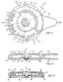
- FIG 9 shows a perspective view of the housing 11 constituting an embodiment of this device 10.
- This housing 11 is cylindrical with an axis of revolution A. It is preferably made of plastic and consists of a bottom 20 and a cover 21 which advantageously adapt to one another by interlocking.
- the bottom 20 has an opening 23 (see Figure 11) while the cover has a valve 50 adapted to cooperate with this opening 23 to open or close it depending on the gas pressure in the pocket increases or decreases, mainly when the user so desires.
- This cover 21 is better visible in Figure 10 which, moreover, shows it turned over so that the inside of the cover is visible.
- a cylindrical wall 41 having a free end 42. Externally and opposite this end, an ear 45 protrudes radially on the wall 41.
- the end 42 of the wall 41 is moreover provided with two sectoral edges 43 projecting radially outwards. They each extend over a sector of approximately 90 ° and are diametrically opposite.
- axial recesses 49 - in this case eight - are made in the wall 41.
- the wall 41 surrounds a flat part or margin 40 of the cover 21 having the shape of a peripheral crown. Windows 39 pierced in the margin 40 thus come in the extension of the axial recesses 49.
- valve 50 which consists first of all of a crown 51 of material thinner than that of the margin 40. It is bordered externally by a recess 56 ensuring the transition between the margin 40 and the thinned crown 51. Similarly, the thinned crown 51 is bordered internally by another recess 57. Thus the crown 51 allows a disc 61 in the center of the valve to move relative to the margin 40.
- the whole margin 40 - thinned crown 51 - disc 61 is molded in such a way so that in the rest position, the disc 61 is located, relative to the plane of the margin 40, in a plane located more inside the cover 21. Consequently, the thinned crown 51 plays the role of elastic means which ensure the return of the disc 61 towards the inside of the housing 11.
- the valve 50 closing member is also constituted by the disc 61 on which protrudes a stud 62 surrounded by three lateral bosses 66 extending in directions making 120 ° relative to each other.
- the stud 62 has a free end terminated by a needle whose size is chosen to partially penetrate the opening 23 and thus close it. The latter protrudes from the free ends 68 of the bosses 66 which are, in turn, flat.
- the bottom 20 is shown in Figure 11. It has a cylindrical wall 30. Externally, an ear 35 extends radially at a level opposite to the free end of the wall 30. Internally, and this time level with the free end of the wall 30, sectoral edges 33 project radially inward. Each of them extends over an area of approximately 35 °. There are two pairs of flanges 33 each extending over a total sector of approximately 90 ° which are diametrically opposite. A rim 33 of each pair is extended by an axial column 34 integral with the wall 30.
- the wall 30 of the bottom 20 surrounds a flat part 22 which has days 29 arranged opposite the flanges 33. They are in fact made necessary for the molding of the bottom 20 by injection.
- the opening 23 intended to communicate with the interior of the ostomy bag.
- the opening 23 is provided on its inner rim with the housing with a sealing lip 27.
- An annular relief 25 projects on the flat part 22 almost halfway between the cylindrical wall 30 and the opening 23.
- three guides 36 in the form of helical ramps 38 rising relative to the flat part 22 of the bottom 20 for example, as shown, in the opposite direction of watch hands are arranged around the opening 23.
- the box internally delimits a space 19 which is capable of accommodating a filter.
- a space 19 which is capable of accommodating a filter.
- Figures 12 to 14 relate to the open position of the valve 50.
- the bosses 66 and the ramps 36 are shown in dotted lines, it can be seen that it is produced when cover 21 and bottom 20 have been turned relative to each other so that the end 68 of the bosses 66 rests on the highest part of the ramps 38, that is to say is in the high position.
- the mobility offered by the thinned crown 51 this causes the needle of the stud 62 to be withdrawn from the opening 23.
- the gases can then pass through the opening 23 between the lip 27 and the needle according to the arrows in Figures 13 and 14.
- the gases are evacuated outside through the windows 39 of the cover 21. If a filter is present in the interior space 19 of the housing 11, the gases are then forced to pass through this filter . They find their way to the windows 39 thanks to the recesses 49 in the wall 41 that the filter cannot obstruct because of their recessed shape.
- Figures 15 and 16 relate to the closed position of the valve 50.
- the bosses 66 are supported at the other end of the ramp 38 of the guides 36, that is to say are in the low position.
- the needle of the stud 62 can penetrate inside the opening 23. It is held there by the restoring force provided by the elastic effect due to the molding conditions of the margin 40 - crown assembly thinned 51 - disc 61.
- the collaboration of the needle with the lip 27 ensures the sealing of the closure.
- the column 34 located at one end of a rim 33 for its part, provides a stop which prevents the cover 51 from being turned too much with respect to the bottom 20 and prevents the bosses 66 from consequently coming completely out of the ramps 38.
- valve 50 can to a certain extent open automatically if the pressure of the gases in the pocket becomes so high that by applying to the surface of the needle through the opening 23, they manage to exert a force capable of overcoming the restoring force of the elastic means constituted by the thinned crown 51.
- the gases escape through the filter when the valve is closed and directly through the opening 15 of the filter and therefore without passing inside the latter when the valve is open.
- the closing of the valve opposes any escape of gas and makes the bag watertight while when it is open, the gases are forced to pass inside the filter.
Landscapes
- Health & Medical Sciences (AREA)
- Heart & Thoracic Surgery (AREA)
- Life Sciences & Earth Sciences (AREA)
- Orthopedic Medicine & Surgery (AREA)
- Engineering & Computer Science (AREA)
- Biomedical Technology (AREA)
- Epidemiology (AREA)
- Vascular Medicine (AREA)
- Nursing (AREA)
- Animal Behavior & Ethology (AREA)
- General Health & Medical Sciences (AREA)
- Public Health (AREA)
- Veterinary Medicine (AREA)
- Orthopedics, Nursing, And Contraception (AREA)
- Infusion, Injection, And Reservoir Apparatuses (AREA)
Applications Claiming Priority (4)
| Application Number | Priority Date | Filing Date | Title |
|---|---|---|---|
| FR9313246 | 1993-11-08 | ||
| FR9313246A FR2712181B1 (fr) | 1993-11-08 | 1993-11-08 | Dispositif de dégazage et de contrôle de la pression interne d'une poche de recueil pour stomie. |
| FR9405805A FR2719765B3 (fr) | 1994-05-11 | 1994-05-11 | Dispositif de dégazage et de contrôle de la pression interne d'une poche de recueil pour stomie. |
| FR9405805 | 1994-05-11 |
Publications (2)
| Publication Number | Publication Date |
|---|---|
| EP0653196A1 true EP0653196A1 (de) | 1995-05-17 |
| EP0653196B1 EP0653196B1 (de) | 1998-05-06 |
Family
ID=26230717
Family Applications (1)
| Application Number | Title | Priority Date | Filing Date |
|---|---|---|---|
| EP94402501A Expired - Lifetime EP0653196B1 (de) | 1993-11-08 | 1994-11-07 | Ventil und innendrucksteuervorrichtung für Ostomiebeutel |
Country Status (6)
| Country | Link |
|---|---|
| US (1) | US5626569A (de) |
| EP (1) | EP0653196B1 (de) |
| JP (1) | JPH07265344A (de) |
| AT (1) | ATE165728T1 (de) |
| DE (1) | DE69410062T2 (de) |
| ES (1) | ES2117773T3 (de) |
Cited By (2)
| Publication number | Priority date | Publication date | Assignee | Title |
|---|---|---|---|---|
| EP0868892A1 (de) | 1997-04-02 | 1998-10-07 | Bristol-Myers Squibb Company | Entlüftungsventil für einen Ostomiebeutel |
| US10449081B2 (en) | 2017-02-18 | 2019-10-22 | Choon Kee Lee | Ostomy apparatus |
Families Citing this family (27)
| Publication number | Priority date | Publication date | Assignee | Title |
|---|---|---|---|---|
| DK171343B1 (da) * | 1994-09-30 | 1996-09-16 | Coloplast As | Filterarrangement til en pose til opsamling af udskilte legemssekreter |
| US5758231A (en) * | 1996-12-20 | 1998-05-26 | Lexmark International, Inc. | Venting plug in toner cartridge |
| GB2334678B (en) * | 1998-02-25 | 2000-10-04 | Bristol Myers Squibb Co | Venting device for an ostomy appliance |
| DK199901606A (da) * | 1999-11-08 | 2001-05-09 | Nystrup Mogens | Ventil til automatisk udluftning af stomiposer m.fl. og til kontrol af gasflow gennem et desodoriseringsfilter |
| KR20040004619A (ko) * | 2001-05-11 | 2004-01-13 | 컴퓨터 어소시에이츠 싱크, 인코포레이티드 | 구식 소프트웨어 애플리케이션을 최신의 객체 지향시스템으로 전환하는 방법과 시스템 |
| DK175563B1 (da) * | 2002-02-05 | 2004-12-06 | Coloplast As | Stomiindretning |
| US20030236509A1 (en) * | 2002-06-25 | 2003-12-25 | Silvestrini Edgar Ignacio | Colostomy bag with gas release valve and method for releasing gas collected in the colostomy bag |
| US7455580B2 (en) * | 2004-11-24 | 2008-11-25 | San Ford Machinery Co., Ltd. | Dry spray device |
| US7976522B2 (en) * | 2005-05-20 | 2011-07-12 | Coloplast A/S | Appliance for irrigation and/or drainage |
| US7326190B2 (en) * | 2005-05-25 | 2008-02-05 | Hollister Incorporated | Ostomy pouch and high performance deodorizing gas filter assembly therefor |
| GB0521078D0 (en) * | 2005-10-17 | 2005-11-23 | T G Eakin Ltd | Access port for a medical appliance and method |
| US7753979B2 (en) * | 2006-02-10 | 2010-07-13 | Home Health Medical Equipment, Inc. | Filter assembly with adjustable inlet opening |
| US20080118190A1 (en) * | 2006-10-17 | 2008-05-22 | Highland Champ Corporation | Exhaust valve for vacuum bag |
| US7713320B2 (en) * | 2006-12-29 | 2010-05-11 | Illinois Tool Works Inc. | Evacuable bag having filter for reducing particulate contamination of vacuum valve |
| US7803206B2 (en) * | 2007-07-26 | 2010-09-28 | Hewlett-Packard Development Company, L.P. | Electronic device filter assembly |
| US20090050512A1 (en) * | 2007-08-24 | 2009-02-26 | Linh Pham | One-way valve with flapper concept for vacuum bag |
| US20090194091A1 (en) * | 2008-02-05 | 2009-08-06 | Ming Dong | Barbecue grill |
| WO2011057635A1 (en) * | 2009-11-10 | 2011-05-19 | Coloplast A/S | A filter - case for a coupling for an ostomy appliance |
| US8657799B2 (en) | 2011-11-07 | 2014-02-25 | Georgann M. Carrubba | Ostomy appliance and method |
| GB2506353A (en) * | 2012-09-26 | 2014-04-02 | Roger Higgins | Pressure sensor to assist in the management of a surgical stoma |
| US9427710B2 (en) * | 2013-03-15 | 2016-08-30 | Bemis Company, Inc. | Radial filtration vent and medical device packaging |
| EP3157477B1 (de) * | 2014-06-23 | 2020-08-05 | Entrenous, LLC | Vorrichtungen für stomagasmanagement |
| US9757270B2 (en) | 2015-02-09 | 2017-09-12 | Tencar Inc. | Ostomy appliance |
| WO2017141190A1 (en) * | 2016-02-18 | 2017-08-24 | Mracna Aaron J | Ostomy pouch vent and method of venting an ostomy pouch |
| KR101900300B1 (ko) | 2016-03-10 | 2018-09-19 | 조재영 | 인공항문 주머니의 가스배출장치 |
| USD848608S1 (en) | 2016-10-21 | 2019-05-14 | Coloplast A/S | Base unit for anal irrigation and controller |
| CN111839874A (zh) * | 2018-12-26 | 2020-10-30 | 南通市第一人民医院 | 一种环保型多功能造口袋及其防护层 |
Citations (5)
| Publication number | Priority date | Publication date | Assignee | Title |
|---|---|---|---|---|
| GB2094153A (en) * | 1981-03-09 | 1982-09-15 | Johnson & Johnson | Colostomy appliance and pressure relief valve therefor |
| FR2514636A1 (fr) * | 1981-10-15 | 1983-04-22 | Int Ostomy Products Aps | Dispositif de ventilation pour sac collecteur de matieres a evacuer en chirurgie abdominale |
| GB2116433A (en) * | 1982-03-16 | 1983-09-28 | Hollister Inc | Ostomy pouch |
| US4451258A (en) * | 1982-03-04 | 1984-05-29 | E. R. Squibb & Sons, Inc. | Ostomy bag with an adjustable vent |
| DE3304311A1 (de) * | 1983-02-09 | 1984-08-16 | Sorbexx GmbH Gesellschaft für Adsorptionstechnik und Verbundstoffe, 8586 Gefrees | Vorrichtung zum entlueften von kolostomiebeuteln |
Family Cites Families (13)
| Publication number | Priority date | Publication date | Assignee | Title |
|---|---|---|---|---|
| FR1381556A (fr) * | 1963-10-31 | 1964-12-14 | Filtre destiné notamment au dosage des poussières atmosphériques | |
| BE795570A (fr) * | 1972-02-17 | 1973-06-18 | Beskyttede Virksomheder | Sac de colostomie ou d'ileostomie |
| US3865109A (en) * | 1973-03-16 | 1975-02-11 | Austin E Elmore | Colostomy fecal pouch venting means |
| US4232672A (en) * | 1978-08-02 | 1980-11-11 | Kingsdown Medical Consultants Limited | Ostomy coupling including a venting valve |
| US4268286A (en) * | 1980-07-24 | 1981-05-19 | Kingsdown Medical Consultants Limited | Attachable filter and ostomy bag including same |
| US4387671A (en) * | 1981-07-13 | 1983-06-14 | Jarvis Robert D | Air filter for a cooling system overflow container |
| US4516974A (en) * | 1982-12-13 | 1985-05-14 | Imnetec Inc. | Universal vent device and method for ostomy appliances |
| DE3304312C1 (de) * | 1983-02-09 | 1984-06-14 | Sorbexx GmbH Gesellschaft für Adsorptionstechnik und Verbundstoffe, 8586 Gefrees | Kolostomiebeutel mit einer Einrichtung zur Filterung und kontrollierten Abfuehrung der Gase |
| FR2615099B1 (fr) * | 1987-05-14 | 1996-08-23 | Biotrol Sa Lab | Systeme de filtre a event de degazage incorpore, destine a etre monte dans des poches de drainage d'anus artificiels au cours de leur fabrication |
| US4938749A (en) * | 1988-09-09 | 1990-07-03 | E. R. Squibb & Sons, Inc. | Ostomy pouch filter housing |
| US4957518A (en) * | 1989-06-06 | 1990-09-18 | Brassell Gilbert W | Assembly useful for retaining components such as a filter to a container and a corresponding combination |
| GB9207007D0 (en) * | 1992-03-28 | 1992-05-13 | Smiths Industries Plc | Medico-surgical collection bags |
| US5372594A (en) * | 1993-08-02 | 1994-12-13 | Colacello; Albert A. | Colostomy pouche with vent valve |
-
1994
- 1994-11-03 US US08/333,643 patent/US5626569A/en not_active Expired - Fee Related
- 1994-11-07 AT AT94402501T patent/ATE165728T1/de not_active IP Right Cessation
- 1994-11-07 DE DE69410062T patent/DE69410062T2/de not_active Expired - Fee Related
- 1994-11-07 EP EP94402501A patent/EP0653196B1/de not_active Expired - Lifetime
- 1994-11-07 ES ES94402501T patent/ES2117773T3/es not_active Expired - Lifetime
- 1994-11-08 JP JP6274053A patent/JPH07265344A/ja active Pending
Patent Citations (5)
| Publication number | Priority date | Publication date | Assignee | Title |
|---|---|---|---|---|
| GB2094153A (en) * | 1981-03-09 | 1982-09-15 | Johnson & Johnson | Colostomy appliance and pressure relief valve therefor |
| FR2514636A1 (fr) * | 1981-10-15 | 1983-04-22 | Int Ostomy Products Aps | Dispositif de ventilation pour sac collecteur de matieres a evacuer en chirurgie abdominale |
| US4451258A (en) * | 1982-03-04 | 1984-05-29 | E. R. Squibb & Sons, Inc. | Ostomy bag with an adjustable vent |
| GB2116433A (en) * | 1982-03-16 | 1983-09-28 | Hollister Inc | Ostomy pouch |
| DE3304311A1 (de) * | 1983-02-09 | 1984-08-16 | Sorbexx GmbH Gesellschaft für Adsorptionstechnik und Verbundstoffe, 8586 Gefrees | Vorrichtung zum entlueften von kolostomiebeuteln |
Cited By (2)
| Publication number | Priority date | Publication date | Assignee | Title |
|---|---|---|---|---|
| EP0868892A1 (de) | 1997-04-02 | 1998-10-07 | Bristol-Myers Squibb Company | Entlüftungsventil für einen Ostomiebeutel |
| US10449081B2 (en) | 2017-02-18 | 2019-10-22 | Choon Kee Lee | Ostomy apparatus |
Also Published As
| Publication number | Publication date |
|---|---|
| US5626569A (en) | 1997-05-06 |
| ES2117773T3 (es) | 1998-08-16 |
| JPH07265344A (ja) | 1995-10-17 |
| DE69410062T2 (de) | 1998-09-03 |
| ATE165728T1 (de) | 1998-05-15 |
| EP0653196B1 (de) | 1998-05-06 |
| DE69410062D1 (de) | 1998-06-10 |
Similar Documents
| Publication | Publication Date | Title |
|---|---|---|
| EP0653196B1 (de) | Ventil und innendrucksteuervorrichtung für Ostomiebeutel | |
| EP0521188B1 (de) | Gerät zum Extrahieren von Kartuschen | |
| EP0286501B1 (de) | Sicherheitsvorrichtung für einen Stoma-Apparat | |
| BE1006543A3 (fr) | Dispositif de fermeture a liberation automatique pour recipients. | |
| EP0549450B1 (de) | Handschuhhalteeinrichtung für Isolierraum | |
| EP0927307B1 (de) | Peristaltische miniatur-pumpe | |
| EP0927306B1 (de) | Tragbare peristaltische pumpe | |
| FR3067011A1 (fr) | Embout et dispositif de distribution de liquide comprenant un capuchon | |
| EP1633646B1 (de) | Verschluss mit einem entriegelbaren, elastisch rückfedernden deckel | |
| CH620357A5 (de) | ||
| WO2003006333A2 (fr) | Dispositif de bouchage et recipient equipe d'un tel dispositif | |
| FR2904297A1 (fr) | Dispositif de distribution de produit fluide. | |
| WO1997047531A1 (fr) | Bouchon avec clapet pour recipient | |
| FR2502591A1 (fr) | Assemblage de liaison pour systemes a deux composantes | |
| EP2683622A1 (de) | Behälter, insbesondere eine wanne für ein kosmetisches produkt, und herstellungsverfahren dafür | |
| EP1075203A1 (de) | Fritiergerät mit filteranlage für den haushalt | |
| WO2010004229A1 (fr) | Dispositif d'inhalation de poudre | |
| WO2015150704A1 (fr) | Dispositif de stockage d'au moins une lentille de contact a usage limite | |
| EP0941724B1 (de) | Stomavorrichtung | |
| FR2640875A1 (de) | ||
| WO2022096839A1 (fr) | Dispositif de remplissage d'un contenant tel qu'une capsule, notamment une capsule pour machine à café | |
| FR3067009B1 (fr) | Embout et dispositif de distribution de liquide comprenant un capuchon | |
| EP0466564B1 (de) | Auseinandernehmbarer Behälter, der für einen internen Druck ausgelegt ist | |
| FR2712181A1 (fr) | Dispositif de dégazage et de contrôle de la pression interne d'une poche de recueil pour stomie. | |
| FR2719765A1 (fr) | Dispositif de dégazage et de contrôle de la pression interne d'une poche de recueil pour stomie. |
Legal Events
| Date | Code | Title | Description |
|---|---|---|---|
| PUAI | Public reference made under article 153(3) epc to a published international application that has entered the european phase |
Free format text: ORIGINAL CODE: 0009012 |
|
| AK | Designated contracting states |
Kind code of ref document: A1 Designated state(s): AT CH DE ES FR GB IT LI NL |
|
| 17P | Request for examination filed |
Effective date: 19950609 |
|
| GRAG | Despatch of communication of intention to grant |
Free format text: ORIGINAL CODE: EPIDOS AGRA |
|
| RAP1 | Party data changed (applicant data changed or rights of an application transferred) |
Owner name: B. BRAUN BIOTROL |
|
| 17Q | First examination report despatched |
Effective date: 19970818 |
|
| GRAG | Despatch of communication of intention to grant |
Free format text: ORIGINAL CODE: EPIDOS AGRA |
|
| GRAH | Despatch of communication of intention to grant a patent |
Free format text: ORIGINAL CODE: EPIDOS IGRA |
|
| GRAH | Despatch of communication of intention to grant a patent |
Free format text: ORIGINAL CODE: EPIDOS IGRA |
|
| GRAA | (expected) grant |
Free format text: ORIGINAL CODE: 0009210 |
|
| AK | Designated contracting states |
Kind code of ref document: B1 Designated state(s): AT CH DE ES FR GB IT LI NL |
|
| REF | Corresponds to: |
Ref document number: 165728 Country of ref document: AT Date of ref document: 19980515 Kind code of ref document: T |
|
| REG | Reference to a national code |
Ref country code: CH Ref legal event code: EP |
|
| GBT | Gb: translation of ep patent filed (gb section 77(6)(a)/1977) |
Effective date: 19980506 |
|
| REF | Corresponds to: |
Ref document number: 69410062 Country of ref document: DE Date of ref document: 19980610 |
|
| REG | Reference to a national code |
Ref country code: CH Ref legal event code: NV Representative=s name: ISLER & PEDRAZZINI AG |
|
| ITF | It: translation for a ep patent filed | ||
| REG | Reference to a national code |
Ref country code: ES Ref legal event code: FG2A Ref document number: 2117773 Country of ref document: ES Kind code of ref document: T3 |
|
| PLBE | No opposition filed within time limit |
Free format text: ORIGINAL CODE: 0009261 |
|
| STAA | Information on the status of an ep patent application or granted ep patent |
Free format text: STATUS: NO OPPOSITION FILED WITHIN TIME LIMIT |
|
| 26N | No opposition filed | ||
| REG | Reference to a national code |
Ref country code: GB Ref legal event code: IF02 |
|
| PGFP | Annual fee paid to national office [announced via postgrant information from national office to epo] |
Ref country code: GB Payment date: 20031114 Year of fee payment: 10 Ref country code: DE Payment date: 20031114 Year of fee payment: 10 Ref country code: CH Payment date: 20031114 Year of fee payment: 10 |
|
| PGFP | Annual fee paid to national office [announced via postgrant information from national office to epo] |
Ref country code: NL Payment date: 20031118 Year of fee payment: 10 |
|
| PGFP | Annual fee paid to national office [announced via postgrant information from national office to epo] |
Ref country code: FR Payment date: 20031119 Year of fee payment: 10 Ref country code: AT Payment date: 20031119 Year of fee payment: 10 |
|
| PGFP | Annual fee paid to national office [announced via postgrant information from national office to epo] |
Ref country code: ES Payment date: 20031124 Year of fee payment: 10 |
|
| PG25 | Lapsed in a contracting state [announced via postgrant information from national office to epo] |
Ref country code: GB Free format text: LAPSE BECAUSE OF NON-PAYMENT OF DUE FEES Effective date: 20041107 Ref country code: AT Free format text: LAPSE BECAUSE OF NON-PAYMENT OF DUE FEES Effective date: 20041107 |
|
| PG25 | Lapsed in a contracting state [announced via postgrant information from national office to epo] |
Ref country code: ES Free format text: LAPSE BECAUSE OF NON-PAYMENT OF DUE FEES Effective date: 20041108 |
|
| PG25 | Lapsed in a contracting state [announced via postgrant information from national office to epo] |
Ref country code: LI Free format text: LAPSE BECAUSE OF NON-PAYMENT OF DUE FEES Effective date: 20041130 Ref country code: CH Free format text: LAPSE BECAUSE OF NON-PAYMENT OF DUE FEES Effective date: 20041130 |
|
| PG25 | Lapsed in a contracting state [announced via postgrant information from national office to epo] |
Ref country code: NL Free format text: LAPSE BECAUSE OF NON-PAYMENT OF DUE FEES Effective date: 20050601 Ref country code: DE Free format text: LAPSE BECAUSE OF NON-PAYMENT OF DUE FEES Effective date: 20050601 |
|
| GBPC | Gb: european patent ceased through non-payment of renewal fee |
Effective date: 20041107 |
|
| REG | Reference to a national code |
Ref country code: CH Ref legal event code: PL |
|
| PG25 | Lapsed in a contracting state [announced via postgrant information from national office to epo] |
Ref country code: FR Free format text: LAPSE BECAUSE OF NON-PAYMENT OF DUE FEES Effective date: 20050729 |
|
| NLV4 | Nl: lapsed or anulled due to non-payment of the annual fee |
Effective date: 20050601 |
|
| REG | Reference to a national code |
Ref country code: FR Ref legal event code: ST |
|
| PG25 | Lapsed in a contracting state [announced via postgrant information from national office to epo] |
Ref country code: IT Free format text: LAPSE BECAUSE OF NON-PAYMENT OF DUE FEES;WARNING: LAPSES OF ITALIAN PATENTS WITH EFFECTIVE DATE BEFORE 2007 MAY HAVE OCCURRED AT ANY TIME BEFORE 2007. THE CORRECT EFFECTIVE DATE MAY BE DIFFERENT FROM THE ONE RECORDED. Effective date: 20051107 |
|
| REG | Reference to a national code |
Ref country code: ES Ref legal event code: FD2A Effective date: 20041108 |