EP0653213A2 - Procédé et installation pour la désinfection de déchets - Google Patents
Procédé et installation pour la désinfection de déchets Download PDFInfo
- Publication number
- EP0653213A2 EP0653213A2 EP94117643A EP94117643A EP0653213A2 EP 0653213 A2 EP0653213 A2 EP 0653213A2 EP 94117643 A EP94117643 A EP 94117643A EP 94117643 A EP94117643 A EP 94117643A EP 0653213 A2 EP0653213 A2 EP 0653213A2
- Authority
- EP
- European Patent Office
- Prior art keywords
- waste
- steam
- container
- frame
- waste containers
- Prior art date
- Legal status (The legal status is an assumption and is not a legal conclusion. Google has not performed a legal analysis and makes no representation as to the accuracy of the status listed.)
- Withdrawn
Links
Images


Classifications
-
- A—HUMAN NECESSITIES
- A61—MEDICAL OR VETERINARY SCIENCE; HYGIENE
- A61L—METHODS OR APPARATUS FOR STERILISING MATERIALS OR OBJECTS IN GENERAL; DISINFECTION, STERILISATION OR DEODORISATION OF AIR; CHEMICAL ASPECTS OF BANDAGES, DRESSINGS, ABSORBENT PADS OR SURGICAL ARTICLES; MATERIALS FOR BANDAGES, DRESSINGS, ABSORBENT PADS OR SURGICAL ARTICLES
- A61L11/00—Methods specially adapted for refuse
-
- A—HUMAN NECESSITIES
- A61—MEDICAL OR VETERINARY SCIENCE; HYGIENE
- A61L—METHODS OR APPARATUS FOR STERILISING MATERIALS OR OBJECTS IN GENERAL; DISINFECTION, STERILISATION OR DEODORISATION OF AIR; CHEMICAL ASPECTS OF BANDAGES, DRESSINGS, ABSORBENT PADS OR SURGICAL ARTICLES; MATERIALS FOR BANDAGES, DRESSINGS, ABSORBENT PADS OR SURGICAL ARTICLES
- A61L2/00—Disinfection or sterilisation of materials or objects, in general; Accessories therefor
- A61L2/02—Disinfection or sterilisation of materials or objects, in general; Accessories therefor using physical processes
- A61L2/04—Heat
- A61L2/06—Hot gas
-
- A—HUMAN NECESSITIES
- A61—MEDICAL OR VETERINARY SCIENCE; HYGIENE
- A61L—METHODS OR APPARATUS FOR STERILISING MATERIALS OR OBJECTS IN GENERAL; DISINFECTION, STERILISATION OR DEODORISATION OF AIR; CHEMICAL ASPECTS OF BANDAGES, DRESSINGS, ABSORBENT PADS OR SURGICAL ARTICLES; MATERIALS FOR BANDAGES, DRESSINGS, ABSORBENT PADS OR SURGICAL ARTICLES
- A61L2/00—Disinfection or sterilisation of materials or objects, in general; Accessories therefor
- A61L2/24—Apparatus using programmed or automatic operation
Definitions
- a method for sterilizing hospital waste is already known (DE 39 24 744 C1) in which plastic waste containers filled with said hospital waste and hermetically sealed with a lid are placed on a preparation conveyor belt or a preparation turntable in a lock chamber of a sterilization tunnel, which are then brought hermetically is closed at the end of input.
- a lock door is then opened, through which the waste containers are moved from the preparation conveyor belt or preparation turntable of the lock chamber onto a main conveyor belt or transferred to a main turntable within a sterilization chamber, which is then hermetically sealed.
- Water or disinfectant is injected into each individual waste container via movable injection needles arranged in the sterilization chamber in order to moisten the waste.
- the moistened waste in the waste containers is subjected to a microwave treatment, after the completion of which all the waste containers present in the sterilization chamber are removed again at the discharge end thereof, the lock door to the lock chamber, in which the preparation conveyor belt or preparation turntable is located, hermetically during this unloading process is kept closed.
- the object of the invention is to provide a method and a device for the disinfection of waste contaminated with pathogens or pathogens, which works safely and reliably, is easy to carry out and to handle, and which ensures that Once the waste containers have been closed, no germs or pathogens can escape outdoors either before or during the disinfection process.
- this object is achieved in that in one or at the same time containing multiple wastes and germ-tightly closed by removable lids, waste water from a steam boiler which has been overheated from below of at least 130.degree starts to run when a predetermined internal temperature of at least 110 ° C has been reached in the upper region of the container or all waste containers.
- the device according to the invention for carrying out this method is characterized in that several steam injectors are arranged in a treatment room enclosed by thermal protective walls and forming a horizontal storage surface for connecting one or more waste containers, which are connected to a steam boiler via a valve and the waste containers can be coupled individually with injector valves and that outlet pipe stubs are provided which penetrate the container lid and are connected together via a manifold to a steam condenser, from which the condensate is fed into the steam boiler, and that electrical temperature detectors, each by the Protect the container lid into the individual containers, generate a start signal for a selectable operating time when a preset operating temperature is reached.
- waste containers made of metal and to build them in such a way that they can be reused over a long period of time and very frequently, it being recommended for hygienic reasons to manufacture the waste containers from stainless steel and also in a stable construction, which ensures frequent reuse.
- the method according to the invention is also far superior to the known sterilization method in terms of effectiveness, because with the injected water vapor, for example generated by a high-performance steam boiler, a treatment that can be controlled both thermally and in terms of time can be carried out, by means of which prescribed regulations for achieving complete sterilization or Disinfection of the waste in question from public or private healthcare facilities can ensure the highest possible level of safety.
- the water vapor temperature is between 130 ° C and 200 ° C, the efficiency or disinfection at higher steam temperatures, for example at 180 ° C, being faster than at a temperature close to 130 ° C lying steam temperature.
- the procedure according to claim 4 is of considerable advantage, since it is easy to implement and can be carried out with absolute certainty. There is thus also the possibility of returning the water vapor leaving the waste containers during the treatment period to the steam boiler as condensate, so that fresh water consumption can also be reduced to a minimum.
- the method according to the invention can be carried out not only with the required operational safety but also while ensuring the desired work result of complete disinfection or sterilization of the treated waste, the handling of the waste containers filled with the waste to be treated being very simple is.
- both the outlet pipe socket and the temperature detector can be inserted into the container lid in a manner without the risk that the openings of the individual container lids are freed from their sealing plugs contaminated gases or waste parts can escape.
- the configurations according to claims 7 and 8 serve at the same time to increase this security, while the configuration according to claim 9 represents a very simple, functionally reliable possibility of connecting the individual container interiors with a collecting line, through which the gases escaping with steam during the treatment period are closed Steam cycle can be transferred.
- the sealing plugs provided according to claim 11 are very simple, inexpensive means to tightly close the openings required in the container lids. In addition, they can easily be pushed out of the openings of the container lids into the interior of the container through the outlet pipe sockets to be inserted into these openings or through the protective tubes of the temperature detectors. On in this way it can also be ensured that these openings are sealed again at least approximately simultaneously with the pushing out of the sealing plugs to the outside by the sealing elements of the outlet pipe socket seated on their edge and thus the risk of escape of contaminated gases is reduced to a minimum.
- the centering elements arranged on the storage frame according to claim 13 enable interference-free engagement or coupling of the steam injectors with the injector valves of the individual Waste container ensured.
- the centering elements can consist of conical rings or wedge-shaped fingers.
- the embodiment according to claim 14 ensures not only a simple and at the same time robust design the steam injectors as well as the injector valves but also a very easy handling and inexpensive manufacture. It also ensures a tight connection between the steam injectors and the injector valves.
- the embodiment according to claim 15 also contributes to cost reduction by the storage frame itself being designed as a distributor through which the water vapor supplied via a supply line from the steam boiler is evenly conducted to the individual steam injectors and via these into the individual waste containers.
- the embodiment according to claim 16, 17 and 18 has the advantage that the device can be transported as a whole and preferably easily installed at the location where the waste to be disinfected is produced, the crane according to claim 16 and the garbage press according to claim 17 supplementary aids are, which additionally facilitate the use of the device and the subsequent disposal of the disinfected waste.
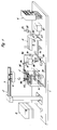
- FIG. 1 shows in a schematically simplified representation a complete device for disinfecting waste, in particular of clinical waste, the components of which, which are described in more detail below, are arranged as a complete system on a portable console 1.
- This console 1 can itself be mobile and equipped for this purpose with a chassis. However, as shown in FIG. 1, it can also be provided only as a supporting element for the parts belonging to the system in the form of a large plate or pallet, which can be transported on a truck and possibly placed on site.
- This device consists essentially of a treatment room 2, a high-performance steam boiler 3, an electrical control unit 4, a crane 5 designed as a column slewing crane and a garbage press 6.
- the crane 5 is arranged between the treatment room 2 and the garbage press 6 so that it it is possible to insert waste container 9 into the treatment chamber 2 with its trolley 8 mounted on a horizontal boom 7 and its lifting device (not shown in detail), to take it out of this and to empty it into the waste press 6.
- the treatment room 2 consists of a rectangular treatment chamber 14 formed, which is provided with four protective walls 10 to 13 and a horizontal floor 15.
- a frame 16 is inserted, which consists of a shelf 17 resting on the floor 15 and a receiving frame 18 arranged vertically above it.
- the storage frame 17 has two longitudinal legs 19 and 20 running parallel to one another and three transverse legs 21, 22 and 23 running at right angles thereto, all of which consist of rectangular tubes and in their grid-like crossing points steam injectors 24 are arranged, which are arranged both in the longitudinal and in Have the same distance from each other in the transverse direction.
- the cavities of the longitudinal legs 19, 20 and the cross legs 21, 22 and 23 are each closed at their front ends, but connected to one another.
- the two longitudinal legs 19 and 20 are connected by connecting pipe sockets 25 and 26 and a connecting pipe 27 to a steam feed line 28 which can be actuated by an electromotive i.e. Openable and closable valve 29 is connected to the high-performance steam boiler 3. (Fig. 1)
- the receiving frame 18 is supported by four vertical supports 31 arranged at the ends of the transverse legs 21 and 23 of the storage frame 17. It consists of three longitudinal spars 32, 33 and 34 and four crossbars 35, 36, 37 and 38, which enclose a total of six squares, the centers of which are perpendicular to the steam injectors 24 of the storage frame 17 and whose width is selected such that a waste container 9 with little lateral play therein laterally can be recorded.
- the steam injectors 24 each consist of a cylindrical flange sleeve 39 with a smaller and thinner upper section 40 and a thicker lower section 41 as well as with one lying on the longitudinal leg 19 or 20 Flange 42 and with a centering projection 43 which projects into a bore 44 of the longitudinal leg 19 or 20. Between the thinner upper section 40 and the thicker, lower section 41 there is a conical ring shoulder 45 on which an elastic sealing ring 46 rests.
- the flange sleeves 39 which form the steam injectors 24 and are tightly inserted with vertical axes 47 in the longitudinal legs 19 and 20 of the storage frame 17, are surrounded by concentrically arranged, upwardly tapering centering elements 48, which here have the shape of conical rings which but also another form z. B. could have the shape of four wedge-shaped fingers.
- the waste containers 9 are all of the same design, so that it is sufficient to describe a single one in its individual parts.
- a waste container 9 consists of a hollow body 50 made of stainless steel sheet that tapers slightly conically downwards. This has at its lower end a cylindrical, double-walled base section 51, at the upper end of which a container base 52, also made of stainless steel sheet, is welded tight.
- This container bottom 52 has an injector valve 53 in its center, which consists of a tightly welded centered pipe socket 54 and a sealing but loosely attached cap 55, preferably made of slightly elastic plastic.
- the bore 56 of the pipe socket 54 has a slightly larger diameter than the upper section 40 of the flange sleeve 39 of a steam injector 24, so that this upper part 40 of the steam injector 24 can be inserted with radial clearance from below into the injector valve 53 or its pipe socket 54.
- the axial aspect ratios are selected so that when the waste container 9 is lowered onto the storage frame 17 and the simultaneous insertion of the upper section 40 of a steam injector 24 into the pipe socket 54 of the injector valve 53, the closure cap 55 from the pipe socket 54 is lifted off and thus the injector valve 53 is opened.
- a plurality of slot openings 57 are provided, through which water vapor, which is supplied via the steam feed line 28, can flow into the interior of the properly placed waste container 9.
- the sealing ring 46 is designed and arranged in such a way that it lies sealingly on the underside of the container bottom 52 when the waste container 9 has the lower edge 58 of its base section 51 on the storage frame 17 sits on.
- Fig. 3 two waste containers 9 are shown, which are parked on the storage frame 17 and the injector valves 53 are connected to the steam injectors 24. It can be seen that the container bottom 52 is seated on the sealing ring 46, which is supported on the conical ring shoulder 45 of the thicker lower part of the flange sleeve 39 forming the steam injector 24. It can also be seen that the two caps 55 are lifted off the pipe socket 54 of the injector valve 53. It can also be imagined that these caps 55 can be put back on the pipe socket 54 when the waste containers 9 are moved upwards and the upper sections 40 of the flange sleeves 39 leave the bores 56 of the pipe socket 54.
- the waste container 9 has in its upper half two diametrically opposed hanging eyes 61 which both as handles as can also be used for hanging chain hooks of the hoist of the crane 5.
- the waste container 9 is closed at the top by means of a slightly curved lid 62, which is seated with a sealing ring 63 on the upper edge 64 of the hollow body 50 and by means of two tension levers 65 and 66, which are diametrically opposed, but offset to the hanging eyes 61 at the upper end of the hollow body 50 are arranged on the outside.
- These tensioning levers 65 and 66 are suspended by two eyelet rings 67 and 68 on tensioning hooks 69 and 70 of the cover and are pivotably supported by hinges 71 and 72, respectively. 5, the clamping levers 65 and 66 are each shown in their closed position, in which the container lid 62 with its sealing ring 63 rests tightly on the upper edge 64 of the waste container 9 under tension.
- Such tension levers 65, 66 are known per se. Therefore, no further explanation of their functioning and handling is required at this point.
- This sealing plug 74 has an annular groove 76 above an annular flange 75, which is designed in this way is that it can accommodate the edge of the opening 73 in a clamping and sealing manner, or that the sealing plug can be inserted from below into the opening 73 in such a way that the opening edge comes to lie in a sealing manner in this annular groove 76 and that the flange 75 thereby its upper end face 77 also fits snugly against the inside of the cover wall 62 '.
- This plug 74 is made of an elastic, heat-resistant material that can withstand temperatures of 200 ° C.
- the sealing plug 74 In order to obtain a tight fit of the sealing plug 74 in the opening 73 of the container lid 72, a relatively high dimensional stability is required. On the other hand, however, the sealing plug 74 should be able to be inserted into the opening 73 relatively easily and without damage as often as possible and also be able to be pushed out of it again.
- the upper part of the sealing plug is provided with a cylindrical recess 78, and the circumferential ring rib 79 lying above the annular groove 76 is provided with a conical surface 80 and 81 on both the top and the bottom.
- this plug 74 is not lost and is always available, it is appropriate to use a connecting element, not shown, for. B. by means of a chain or by means of another to attach flexible connecting element to the inside of the container lid 62.
- the containers 9 are tightly closed in the manner shown in FIG. 5 by means of the covers 62, the openings 73 of which are sealed by the sealing plugs 54.
- the condensate collector 88 is connected by a liquid pump 91 and a return line 93 to the steam boiler 3 so that the condensate collected is returned to the steam circuit of the steam boiler 3, as are the gases sucked off by the vacuum pump 90 and supplied to the steam boiler 3.
- the fresh water supply to the steam boiler 3 takes place via a Line 94 and a valve 95.
- Its burner 96 is supplied with fuel from a fuel tank 97 via a fuel line 97 ′ and controlled by the control unit 4.
- a rectangular grid frame 98 which has two longitudinal frame legs 99 and 100 and three transverse frame legs 101, 102 and 103, which are all in a common plane and consist of interconnected rectangular tubes to which the manifold 85 is connected together.
- this grid frame 98 is pivotable about a horizontal hinge axis 108 on horizontal support arms 109 and 110 of the receiving frame 18 so that it consists of a horizontal closed position, which in FIGS 3 is shown, can be pivoted into a vertical rest position, not shown.
- this grid frame 98 is matched to the storage frame 17.
- six outlet pipe sockets 111 are arranged on the underside so that they are in a coaxial position and perpendicular to the steam injectors 24 of the storage frame 17 when the grid frame 98 occupies its horizontal position shown in FIGS. 2 and 3.
- FIG. 3 in this closed position of the grid frame 98, its outlet pipe connections 111 protrude through the openings 73 of the covers 62 into the interior of the individual waste containers 9. It can also be seen that the sealing plugs 74 are no longer in the openings 73 but inside the container 9.
- the individual outlet pipe sockets 111 By moving the grid frame 98 down from its raised rest position into the horizontal closed position, the individual outlet pipe sockets 111 have pushed the sealing plugs 74 of the individual lids 62 out of the openings 73 into the interior of the container. This creates a connection between the interior of the individual waste containers 9 and the cavities of the grid frame 98 to the collecting line 85.
- the individual outlet pipe sockets 111 are each provided with plate-shaped elastic sealing elements 112 which tightly enclose their upper sections and which in this horizontal closed position of the grid frame 98 also lie sealingly on the covers 62 of the individual waste containers 9, so that through the openings 73, neither parts of the gaseous nor the possibly liquid or even solid contents can escape.
- the individual outlet pipe sockets 111 of the grid frame 98 are thus connected in a sealed manner to the interiors of the individual waste containers 9.
- a clamping bracket 114 is provided which on the side of the receiving frame 18 opposite the support arms 109 and 110 has hinges 115 and 116 pivotably mounted on the frame 16 about a horizontal pivot axis 17 and provided with two clamping screws 118 and 119 with which the grid frame 98 can be pressed with its sealing elements 112 onto the lid 62 of the individual waste containers 9 in the manner shown in FIG. 3.
- electrical temperature detectors 120 are arranged in the outlet pipe sockets 111 of the grid frame 98 in protective tubes 121, which are individually connected to an electrical control circuit and which transmit the temperatures prevailing in the individual waste containers 9 to an electronic one Report the temperature monitoring device.
- This temperature monitoring device is also part of the control unit 4, which moreover contains a data registration device with a printer, which records, processes and processes all the data important for the control and control of the disinfection process holds on. This makes it possible to save the treatment data for each individual waste container in order to have control over the treatment intensity and duration at all times and also to be able to subsequently document the treatment data.
- the gases entering the condenser 86 during the steam supply through the outlet pipe socket 111 and the collecting line 85 which increasingly consist of water vapor with increasing time, reach the condenser 86 and partly via the suction line 89 and the pump 90 back into the steam circuit of the steam boiler 3.
- the condensate accumulating in the condenser 86 reaches the condensate collecting tank 88 via the condensate line 87 and is also automatically fed from there to the steam circuit of the steam boiler 3 by the pump 91 from time to time.
- the individual waste containers are also connected to the steam supply line or their container covers 62 are connected to the collecting line 85 in a very simple and safe manner.
- the decoupling of the waste container 9 both from the steam supply and from the manifold 85 is done in a very simple manner. All that is required is to unlock the clamping bracket 114, pivot it outwards and pivot the grid frame 98 upwards, in order to release all the container lids 62 at the same time.
- the individual waste containers 9 can then be removed individually from the treatment chamber 14 with the aid of the crane 5 and preferably emptied immediately into the waste press 6 in order to then be set up at their usual filling locations.
- the removed container lids 62 are then closed again with the aid of the sealing plugs 74, so that when the waste container 9 is filled again they are available for closure again. Before filling, it is of course necessary to place the cap 55 on the pipe socket 54 so that the injector valves 53 are closed again.
- the walls 10 to 13 and the bottom 15 of the treatment chamber 14 are preferably filled with thermally insulating material so that, on the one hand, protection against contact against combustion and, on the other hand, protection against heat loss and at the same time a reduction in the amount of condensate within the individual waste containers 9 is achieved.
Landscapes
- Health & Medical Sciences (AREA)
- Epidemiology (AREA)
- Life Sciences & Earth Sciences (AREA)
- Animal Behavior & Ethology (AREA)
- General Health & Medical Sciences (AREA)
- Public Health (AREA)
- Veterinary Medicine (AREA)
- Apparatus For Disinfection Or Sterilisation (AREA)
- Processing Of Solid Wastes (AREA)
Applications Claiming Priority (2)
| Application Number | Priority Date | Filing Date | Title |
|---|---|---|---|
| DE4338710 | 1993-11-12 | ||
| DE4338710A DE4338710C2 (de) | 1993-11-12 | 1993-11-12 | Verfahren und Vorrichtung zur Desinfektion von Abfällen |
Publications (2)
| Publication Number | Publication Date |
|---|---|
| EP0653213A2 true EP0653213A2 (fr) | 1995-05-17 |
| EP0653213A3 EP0653213A3 (fr) | 1995-08-09 |
Family
ID=6502473
Family Applications (1)
| Application Number | Title | Priority Date | Filing Date |
|---|---|---|---|
| EP94117643A Withdrawn EP0653213A3 (fr) | 1993-11-12 | 1994-11-09 | Procédé et installation pour la désinfection de déchets. |
Country Status (2)
| Country | Link |
|---|---|
| EP (1) | EP0653213A3 (fr) |
| DE (1) | DE4338710C2 (fr) |
Cited By (1)
| Publication number | Priority date | Publication date | Assignee | Title |
|---|---|---|---|---|
| CN102058896A (zh) * | 2011-01-10 | 2011-05-18 | 林中选 | 一种医疗废弃物的消毒方法 |
Family Cites Families (3)
| Publication number | Priority date | Publication date | Assignee | Title |
|---|---|---|---|---|
| DE3924744C1 (fr) * | 1989-07-26 | 1991-02-07 | Nordpunkt Ag, Novaggio, Ch | |
| DE4234061A1 (de) * | 1992-10-09 | 1994-04-21 | Straehle Andreas | Verfahren und Vorrichtung zum Desinfizieren und/oder Sterilisieren von infektiösem Müll |
| DE4234062A1 (de) * | 1992-10-09 | 1994-04-14 | Straehle Andreas | Vorrichtung zum Desinfizieren und/oder Sterilisieren von infektiösem Müll |
-
1993
- 1993-11-12 DE DE4338710A patent/DE4338710C2/de not_active Expired - Fee Related
-
1994
- 1994-11-09 EP EP94117643A patent/EP0653213A3/fr not_active Withdrawn
Cited By (1)
| Publication number | Priority date | Publication date | Assignee | Title |
|---|---|---|---|---|
| CN102058896A (zh) * | 2011-01-10 | 2011-05-18 | 林中选 | 一种医疗废弃物的消毒方法 |
Also Published As
| Publication number | Publication date |
|---|---|
| EP0653213A3 (fr) | 1995-08-09 |
| DE4338710A1 (de) | 1995-05-18 |
| DE4338710C2 (de) | 1997-07-24 |
Similar Documents
| Publication | Publication Date | Title |
|---|---|---|
| DE69228668T2 (de) | Verfahren und Vorrichtung zur Entsorgung von medizinischen Abfallmaterialien | |
| EP0410306B1 (fr) | Procédé et dispositif pour la stérilisation de déchets, notamment de déchets d'hôpitaux | |
| EP2520496B1 (fr) | Systeme de support presterilisable | |
| DE4236246C2 (de) | Verfahren und Vorrichtung zur Entsorgung von infektionsfähige Keime enthaltendem Material | |
| EP0483104A2 (fr) | Installation pour le chauffage, la désinfection ou la stérilisation de produits | |
| DE3317300C2 (de) | Standfester, verschließbarer Behälter zur Aufnahme eines standfesten Innenbehälters mit Krankenhausabfall | |
| EP0734734B1 (fr) | Procédé et appareil pour la désinfection ou la stérilisation de déchets infectés | |
| DE2207339C3 (de) | Behälter zum Aufbewahren und Transportieren von in Krankenhäusern benötigten Gütern | |
| EP0772558A1 (fr) | Recipient de sterilisation, notamment pour dechets d'hopitaux | |
| EP0697923B1 (fr) | Dispositif d'elimination de dechets | |
| EP0372664B1 (fr) | Autoclave de stérilisation de déchets ou produits similaires | |
| DE4303034C2 (de) | Mobile Desinfektionsanlage, insbesondere für Klinikabfälle | |
| DE4338710C2 (de) | Verfahren und Vorrichtung zur Desinfektion von Abfällen | |
| DE4014856A1 (de) | Fahrbare desinfektionsanlage zur kontinuierlichen desinfektion von krankenhausmuell | |
| DE102010018241A1 (de) | Dampfsterilisationsvorrichtung und Verfahren zur Sterilisierung von kontaminiertem medizinischem und/oder biologischem Material | |
| DE4234062A1 (de) | Vorrichtung zum Desinfizieren und/oder Sterilisieren von infektiösem Müll | |
| DE4235512C2 (de) | Verfahren und Kraftfahrzeug zum Desinfizieren von, insbesondere medizinischem oder dergleichen, Abfall | |
| DE202008009661U1 (de) | Sterilisationsbehälter | |
| WO1994007545A1 (fr) | Appareil de desinfection et de sterilisation de dechets medicaux et son procede d'utilisation | |
| DE4234061A1 (de) | Verfahren und Vorrichtung zum Desinfizieren und/oder Sterilisieren von infektiösem Müll | |
| DE7833722U1 (de) | Behälter zur Sammlung und zum Transport von infektiösen oder nicht keimfreien Abfällen | |
| AT407609B (de) | Desinfektionsapparat und instrumentenbehälter hiefür | |
| DE4108595C2 (fr) | ||
| DE4407311C1 (de) | Verfahren zur Desinfektion oder Sterilisation von Infektionsmüll | |
| DE9411696U1 (de) | Entsorgungsvorrichtung |
Legal Events
| Date | Code | Title | Description |
|---|---|---|---|
| PUAI | Public reference made under article 153(3) epc to a published international application that has entered the european phase |
Free format text: ORIGINAL CODE: 0009012 |
|
| AK | Designated contracting states |
Kind code of ref document: A2 Designated state(s): AT CH ES FR GB IT LI SE |
|
| PUAL | Search report despatched |
Free format text: ORIGINAL CODE: 0009013 |
|
| AK | Designated contracting states |
Kind code of ref document: A3 Designated state(s): AT CH ES FR GB IT LI SE |
|
| 17P | Request for examination filed |
Effective date: 19960203 |
|
| 17Q | First examination report despatched |
Effective date: 19981020 |
|
| GRAG | Despatch of communication of intention to grant |
Free format text: ORIGINAL CODE: EPIDOS AGRA |
|
| GRAG | Despatch of communication of intention to grant |
Free format text: ORIGINAL CODE: EPIDOS AGRA |
|
| GRAH | Despatch of communication of intention to grant a patent |
Free format text: ORIGINAL CODE: EPIDOS IGRA |
|
| GRAH | Despatch of communication of intention to grant a patent |
Free format text: ORIGINAL CODE: EPIDOS IGRA |
|
| STAA | Information on the status of an ep patent application or granted ep patent |
Free format text: STATUS: THE APPLICATION IS DEEMED TO BE WITHDRAWN |
|
| 18D | Application deemed to be withdrawn |
Effective date: 20000601 |