EP0653237A1 - Verfahren zur Verminderung der Stickoxidkonzentration im Abgas einer Brennkraftmaschine oder einer Verbrennungsanlage - Google Patents
Verfahren zur Verminderung der Stickoxidkonzentration im Abgas einer Brennkraftmaschine oder einer Verbrennungsanlage Download PDFInfo
- Publication number
- EP0653237A1 EP0653237A1 EP94115280A EP94115280A EP0653237A1 EP 0653237 A1 EP0653237 A1 EP 0653237A1 EP 94115280 A EP94115280 A EP 94115280A EP 94115280 A EP94115280 A EP 94115280A EP 0653237 A1 EP0653237 A1 EP 0653237A1
- Authority
- EP
- European Patent Office
- Prior art keywords
- exhaust gas
- sensor element
- nitrogen
- ammonia
- concentration
- Prior art date
- Legal status (The legal status is an assumption and is not a legal conclusion. Google has not performed a legal analysis and makes no representation as to the accuracy of the status listed.)
- Granted
Links
Images




Classifications
-
- F—MECHANICAL ENGINEERING; LIGHTING; HEATING; WEAPONS; BLASTING
- F01—MACHINES OR ENGINES IN GENERAL; ENGINE PLANTS IN GENERAL; STEAM ENGINES
- F01N—GAS-FLOW SILENCERS OR EXHAUST APPARATUS FOR MACHINES OR ENGINES IN GENERAL; GAS-FLOW SILENCERS OR EXHAUST APPARATUS FOR INTERNAL-COMBUSTION ENGINES
- F01N3/00—Exhaust or silencing apparatus having means for purifying, rendering innocuous, or otherwise treating exhaust
- F01N3/08—Exhaust or silencing apparatus having means for purifying, rendering innocuous, or otherwise treating exhaust for rendering innocuous
- F01N3/10—Exhaust or silencing apparatus having means for purifying, rendering innocuous, or otherwise treating exhaust for rendering innocuous by thermal or catalytic conversion of noxious components of exhaust
- F01N3/18—Exhaust or silencing apparatus having means for purifying, rendering innocuous, or otherwise treating exhaust for rendering innocuous by thermal or catalytic conversion of noxious components of exhaust characterised by methods of operation; Control
- F01N3/20—Exhaust or silencing apparatus having means for purifying, rendering innocuous, or otherwise treating exhaust for rendering innocuous by thermal or catalytic conversion of noxious components of exhaust characterised by methods of operation; Control specially adapted for catalytic conversion
- F01N3/206—Adding periodically or continuously substances to exhaust gases for promoting purification, e.g. catalytic material in liquid form, NOx reducing agents
- F01N3/208—Control of selective catalytic reduction [SCR], e.g. by adjusting the dosing of reducing agent
-
- B—PERFORMING OPERATIONS; TRANSPORTING
- B01—PHYSICAL OR CHEMICAL PROCESSES OR APPARATUS IN GENERAL
- B01D—SEPARATION
- B01D53/00—Separation of gases or vapours; Recovering vapours of volatile solvents from gases; Chemical or biological purification of waste gases, e.g. engine exhaust gases, smoke, fumes, flue gases, aerosols
- B01D53/30—Controlling by gas-analysis apparatus
-
- B—PERFORMING OPERATIONS; TRANSPORTING
- B01—PHYSICAL OR CHEMICAL PROCESSES OR APPARATUS IN GENERAL
- B01D—SEPARATION
- B01D53/00—Separation of gases or vapours; Recovering vapours of volatile solvents from gases; Chemical or biological purification of waste gases, e.g. engine exhaust gases, smoke, fumes, flue gases, aerosols
- B01D53/34—Chemical or biological purification of waste gases
- B01D53/74—General processes for purification of waste gases; Apparatus or devices specially adapted therefor
- B01D53/86—Catalytic processes
- B01D53/8621—Removing nitrogen compounds
- B01D53/8625—Nitrogen oxides
-
- B—PERFORMING OPERATIONS; TRANSPORTING
- B01—PHYSICAL OR CHEMICAL PROCESSES OR APPARATUS IN GENERAL
- B01D—SEPARATION
- B01D53/00—Separation of gases or vapours; Recovering vapours of volatile solvents from gases; Chemical or biological purification of waste gases, e.g. engine exhaust gases, smoke, fumes, flue gases, aerosols
- B01D53/34—Chemical or biological purification of waste gases
- B01D53/74—General processes for purification of waste gases; Apparatus or devices specially adapted therefor
- B01D53/86—Catalytic processes
- B01D53/8696—Controlling the catalytic process
-
- B—PERFORMING OPERATIONS; TRANSPORTING
- B01—PHYSICAL OR CHEMICAL PROCESSES OR APPARATUS IN GENERAL
- B01D—SEPARATION
- B01D53/00—Separation of gases or vapours; Recovering vapours of volatile solvents from gases; Chemical or biological purification of waste gases, e.g. engine exhaust gases, smoke, fumes, flue gases, aerosols
- B01D53/34—Chemical or biological purification of waste gases
- B01D53/92—Chemical or biological purification of waste gases of engine exhaust gases
- B01D53/94—Chemical or biological purification of waste gases of engine exhaust gases by catalytic processes
- B01D53/9495—Controlling the catalytic process
-
- F—MECHANICAL ENGINEERING; LIGHTING; HEATING; WEAPONS; BLASTING
- F01—MACHINES OR ENGINES IN GENERAL; ENGINE PLANTS IN GENERAL; STEAM ENGINES
- F01N—GAS-FLOW SILENCERS OR EXHAUST APPARATUS FOR MACHINES OR ENGINES IN GENERAL; GAS-FLOW SILENCERS OR EXHAUST APPARATUS FOR INTERNAL-COMBUSTION ENGINES
- F01N3/00—Exhaust or silencing apparatus having means for purifying, rendering innocuous, or otherwise treating exhaust
- F01N3/08—Exhaust or silencing apparatus having means for purifying, rendering innocuous, or otherwise treating exhaust for rendering innocuous
- F01N3/10—Exhaust or silencing apparatus having means for purifying, rendering innocuous, or otherwise treating exhaust for rendering innocuous by thermal or catalytic conversion of noxious components of exhaust
- F01N3/18—Exhaust or silencing apparatus having means for purifying, rendering innocuous, or otherwise treating exhaust for rendering innocuous by thermal or catalytic conversion of noxious components of exhaust characterised by methods of operation; Control
- F01N3/20—Exhaust or silencing apparatus having means for purifying, rendering innocuous, or otherwise treating exhaust for rendering innocuous by thermal or catalytic conversion of noxious components of exhaust characterised by methods of operation; Control specially adapted for catalytic conversion
- F01N3/206—Adding periodically or continuously substances to exhaust gases for promoting purification, e.g. catalytic material in liquid form, NOx reducing agents
-
- G—PHYSICS
- G01—MEASURING; TESTING
- G01N—INVESTIGATING OR ANALYSING MATERIALS BY DETERMINING THEIR CHEMICAL OR PHYSICAL PROPERTIES
- G01N27/00—Investigating or analysing materials by the use of electric, electrochemical, or magnetic means
- G01N27/26—Investigating or analysing materials by the use of electric, electrochemical, or magnetic means by investigating electrochemical variables; by using electrolysis or electrophoresis
- G01N27/403—Cells and electrode assemblies
- G01N27/406—Cells and probes with solid electrolytes
- G01N27/407—Cells and probes with solid electrolytes for investigating or analysing gases
- G01N27/4073—Composition or fabrication of the solid electrolyte
- G01N27/4074—Composition or fabrication of the solid electrolyte for detection of gases other than oxygen
-
- F—MECHANICAL ENGINEERING; LIGHTING; HEATING; WEAPONS; BLASTING
- F01—MACHINES OR ENGINES IN GENERAL; ENGINE PLANTS IN GENERAL; STEAM ENGINES
- F01N—GAS-FLOW SILENCERS OR EXHAUST APPARATUS FOR MACHINES OR ENGINES IN GENERAL; GAS-FLOW SILENCERS OR EXHAUST APPARATUS FOR INTERNAL-COMBUSTION ENGINES
- F01N2560/00—Exhaust systems with means for detecting or measuring exhaust gas components or characteristics
- F01N2560/02—Exhaust systems with means for detecting or measuring exhaust gas components or characteristics the means being an exhaust gas sensor
- F01N2560/021—Exhaust systems with means for detecting or measuring exhaust gas components or characteristics the means being an exhaust gas sensor for measuring or detecting ammonia NH3
-
- F—MECHANICAL ENGINEERING; LIGHTING; HEATING; WEAPONS; BLASTING
- F01—MACHINES OR ENGINES IN GENERAL; ENGINE PLANTS IN GENERAL; STEAM ENGINES
- F01N—GAS-FLOW SILENCERS OR EXHAUST APPARATUS FOR MACHINES OR ENGINES IN GENERAL; GAS-FLOW SILENCERS OR EXHAUST APPARATUS FOR INTERNAL-COMBUSTION ENGINES
- F01N2560/00—Exhaust systems with means for detecting or measuring exhaust gas components or characteristics
- F01N2560/02—Exhaust systems with means for detecting or measuring exhaust gas components or characteristics the means being an exhaust gas sensor
- F01N2560/026—Exhaust systems with means for detecting or measuring exhaust gas components or characteristics the means being an exhaust gas sensor for measuring or detecting NOx
-
- F—MECHANICAL ENGINEERING; LIGHTING; HEATING; WEAPONS; BLASTING
- F01—MACHINES OR ENGINES IN GENERAL; ENGINE PLANTS IN GENERAL; STEAM ENGINES
- F01N—GAS-FLOW SILENCERS OR EXHAUST APPARATUS FOR MACHINES OR ENGINES IN GENERAL; GAS-FLOW SILENCERS OR EXHAUST APPARATUS FOR INTERNAL-COMBUSTION ENGINES
- F01N2610/00—Adding substances to exhaust gases
- F01N2610/02—Adding substances to exhaust gases the substance being ammonia or urea
-
- F—MECHANICAL ENGINEERING; LIGHTING; HEATING; WEAPONS; BLASTING
- F01—MACHINES OR ENGINES IN GENERAL; ENGINE PLANTS IN GENERAL; STEAM ENGINES
- F01N—GAS-FLOW SILENCERS OR EXHAUST APPARATUS FOR MACHINES OR ENGINES IN GENERAL; GAS-FLOW SILENCERS OR EXHAUST APPARATUS FOR INTERNAL-COMBUSTION ENGINES
- F01N2610/00—Adding substances to exhaust gases
- F01N2610/06—Adding substances to exhaust gases the substance being in the gaseous form
-
- F—MECHANICAL ENGINEERING; LIGHTING; HEATING; WEAPONS; BLASTING
- F01—MACHINES OR ENGINES IN GENERAL; ENGINE PLANTS IN GENERAL; STEAM ENGINES
- F01N—GAS-FLOW SILENCERS OR EXHAUST APPARATUS FOR MACHINES OR ENGINES IN GENERAL; GAS-FLOW SILENCERS OR EXHAUST APPARATUS FOR INTERNAL-COMBUSTION ENGINES
- F01N2610/00—Adding substances to exhaust gases
- F01N2610/14—Arrangements for the supply of substances, e.g. conduits
- F01N2610/1453—Sprayers or atomisers; Arrangement thereof in the exhaust apparatus
- F01N2610/146—Control thereof, e.g. control of injectors or injection valves
-
- F—MECHANICAL ENGINEERING; LIGHTING; HEATING; WEAPONS; BLASTING
- F02—COMBUSTION ENGINES; HOT-GAS OR COMBUSTION-PRODUCT ENGINE PLANTS
- F02B—INTERNAL-COMBUSTION PISTON ENGINES; COMBUSTION ENGINES IN GENERAL
- F02B3/00—Engines characterised by air compression and subsequent fuel addition
- F02B3/06—Engines characterised by air compression and subsequent fuel addition with compression ignition
-
- Y—GENERAL TAGGING OF NEW TECHNOLOGICAL DEVELOPMENTS; GENERAL TAGGING OF CROSS-SECTIONAL TECHNOLOGIES SPANNING OVER SEVERAL SECTIONS OF THE IPC; TECHNICAL SUBJECTS COVERED BY FORMER USPC CROSS-REFERENCE ART COLLECTIONS [XRACs] AND DIGESTS
- Y02—TECHNOLOGIES OR APPLICATIONS FOR MITIGATION OR ADAPTATION AGAINST CLIMATE CHANGE
- Y02T—CLIMATE CHANGE MITIGATION TECHNOLOGIES RELATED TO TRANSPORTATION
- Y02T10/00—Road transport of goods or passengers
- Y02T10/10—Internal combustion engine [ICE] based vehicles
- Y02T10/12—Improving ICE efficiencies
Definitions
- the nitrogen oxide and particle emissions (dust) of a diesel engine optimized for performance and consumption can only be reduced insignificantly by means of combustion technology.
- aftertreatment of the diesel engine exhaust gases is therefore essential.
- a significant reduction in NO x emissions from a diesel engine can be achieved by application of the so-called S elective- C atalytic- R eduction technique.
- gaseous ammonia NH3 ammonia in aqueous solution or urea is injected as a reducing agent in the exhaust system, so that in particular the chemical reactions on a catalyst 4NO + 4NH3 + O2 ⁇ 4N2 + 6H2O 2NO2 + 4NH3 + O2 ⁇ 3N2 + 6H2O can expire.
- To reduce 1 mole of NO x in the diesel engine exhaust gas requires about 0.9 to 1.1 moles of NH3. If less ammonia NH3 is injected, the catalyst no longer works with the highest efficiency. Overdosing should also be avoided, as otherwise unused ammonia NH3 will get into the atmosphere.
- the SCR process known from DE 36 10 364 can reduce the proportion of NOx in the exhaust gas from combustion plants by more than 80% and at the same time limit the NH 3 emissions to below 5 ppm.
- the dosage of the reducing agent is monitored Computer that evaluates the output signal of an NH 3 sensor arranged in the exhaust tract behind the NO x converter and, if necessary, readjustes the supply of reducing agent by controlling a delivery unit.
- An NH3 sensor is an electrochemical cell, which contains a cup-shaped body made of stabilized zirconium dioxide as an essential component. Two electrodes are applied to the solid electrolyte, the outer electrode exposed to the exhaust gas being made, for example, of TiO2, Pt V2O5 or V2O5 and the inner electrode exposed to a reference gas (air) made of platinum.
- the advantage that can be achieved with the invention is, in particular, that the NH3 amount required for a stoichiometric conversion of nitrogen monoxide NO to nitrogen N2 and water H2O in a simple manner by measuring the electrical resistance of a vanadate layer exposed to the exhaust gas can determine. An absolute measurement of the NO or NH3 concentration is not necessary. Since the aim of the control is a maximum resistance of the metal oxide layer used as the sensor element, any resistance drift that may be present does not cause any problems.
- the exhaust system of a diesel engine 1 shown schematically in FIG. 1 is said to largely break down the nitrogen oxides NOx formed during operation and to release the remaining residual gases to the atmosphere with as little noise as possible. It consists of an SCR catalytic converter 2 described in / 1 / and / 2 /, one or more switching dampers 3 and a pipe system 4 which connects the individual components to the exhaust gas outlet openings present in the cylinder head of the diesel engine 1.
- Upstream of the SCR catalytic converter 2 is a metering device 5, which is stored in a storage container 6 Injecting reducing agent into the exhaust tract.
- the metering device 5 contains in particular a membrane pump connected to an injection nozzle 7 or an injection valve with an upstream flow meter.
- a control unit 8 ensures that a certain amount of the ammonia-containing reducing agent can be supplied to the exhaust gas.
- a particularly suitable reducing agent is an aqueous urea solution (CO (NH2) 2). This is decomposed with the addition of heat to carbon dioxide CO2 and ammonia NH3, the ammonia NH3 adsorbed on the surface of the catalyst 2 and reacts with the nitrogen oxides NO and NO2 present in the exhaust gas to form the non-toxic substances nitrogen N2 and water H2O.
- CO aqueous urea solution
- the reaction must 4NH3 + 4NO + O2 ⁇ 4N2 + 6H2O run stoichiometrically.
- the NO or NH3 concentration is therefore measured with the aid of a detector 9 arranged in the exhaust pipe 4 behind the SCR catalytic converter 2 and used to control the amount of urea injected.
- the amount of urea required for a stoichiometric reaction is then injected due to the properties of the detector to be described when the electrical resistance of a vanadate layer used as an NO- or NH3-sensitive element passes through a maximum or its electrical conductivity passes through a minimum.
- the detector 9 is actively heated with the aid of a resistance layer arranged on the rear side of the substrate 10.
- the resistance layer designated 17 in FIG. 2 consists, for example, of platinum (Pt), gold (Au) or an electrically conductive ceramic and has a meandering structure. Also shown is the approximately 10 to 100 nm thick metal layer 18 consisting of titanium (Ti), chromium (Cr), nickel (Ni) or tungsten (W), which improves the adhesion between the substrate 10 and the platinum electrodes 11, 11 ' .
- the dimensions of the comb electrodes 11 and 11 ' depend on the specific resistance of the sensor layer 12 applied over it in the desired temperature range.
- the comb structure 11, 11 ′ can have thicknesses of 0.1 to 10 ⁇ m, widths of 1 to 1000 ⁇ m and electrode spacings of 1 to 100 ⁇ m.
- electrode thickness D 1.5 ⁇ m
- length of the interdigital structure L 1 mm
- electrode spacing S 50 ⁇ m.
- FIG. 4 shows a scale representation of an interdigital structure in a top view.
- a platinum resistance layer 19 is used as the temperature sensor.
- a 1.5 ⁇ m thick platinum layer 20 is first deposited on the heated corundum substrate 10 in a sputtering system (see FIGS. 5a, b).
- the structuring of the layer 20 takes place in a positive photo step, in which the photoresist 21 is applied at the location of the electrodes to be produced and exposed through a mask 22 (see FIG. 5c, d, e).
- the developed photoresist 21 protects the platinum layer 20 during the subsequent etching step (see FIG. 5f).
- the desired comb electrodes 11 and 11 '(see FIG. 5g) are obtained, on which the gas-sensitive vanadate layer 12 is subsequently deposited (see FIG. 5h).
- the extraordinary properties of the detector are based on the sputtering method to be used in the production of the gas-sensitive layer 12 and the subsequent tempering.
- Metallic vanadium (V) and aluminum (Al) serve as starting materials, which are reactively atomized from corresponding targets in a plasma consisting of 80% argon and 20% oxygen and are deposited on the heated substrate 10.
- the sandwich structure 23 shown in FIG. 6 is built up by alternately atomizing the two targets.
- Layers with an Al2O3 content of more than 50% show a somewhat smaller measurement effect. However, they can still be used at higher temperatures of up to 680 ° C.
- the vanadate layer In addition to nitrogen monoxide NO and ammonia NH3, the vanadate layer also responds to changes in the oxygen partial pressure and hydrogen H2 (see FIG. 10).
- the cross sensitivity to oxygen O2 and hydrogen H2 is considerably smaller than the reaction to nitrogen monoxide NO and ammonia NH3.
- 500 ppm of hydrogen H2 in air result in approximately the same change in conductivity as the addition of 10 ppm of nitrogen monoxide NO.
- the gases carbon monoxide CO (up to 1500 ppm), methane CH4 (up to 5000 ppm) and carbon dioxide CO2 (up to 1%) are undetectable up to the concentrations given in brackets.
- a moist gas mixture 80 mbar H2O
- a significant decrease in the NH3 sensitivity is observed; however, it still remains twice as sensitive to nitrogen monoxide NO (see the right part of FIG. 9).
- the sensitivity of the AlVO4 thin film in moist air is shown at 500 ° C and a NO portion of 10 ppm.
- Another gas in the specified concentration was added to the moist air within the time intervals marked by a horizontal line.
- the air therefore contained, for example, 1500 ppm carbon monoxide CO between the 60th and the 120th minute and an additional 10 ppm of nitrogen monoxide NO between the 80th and the 100th minute.
- the NO sensitivity of the AlVO4 layer is not affected by the presence of carbon monoxide CO, methane CH4 and carbon dioxide CO2.
- the addition of hydrogen H2 causes no masking of the NO sensitivity, but a clear cross sensitivity can be determined.
- a similar effect is observed with oxygen O2 when its concentration decreases from 20% to 2%.
- the stainless steel housing shown in FIG. 12 is used to install the detector 9 in the wall of the exhaust pipe 4.
- the housing consists of two parts, the housing head 26 having a gas inlet opening 24 and a metal web 25 on the one with a bore 27 for receiving the detector 9 provided base body 29 is attached. Before welding the two parts 26 and 29, the detector 9 is glued in the bore 27 of the base body 29. After assembly, the sensitive element is located in an S-shaped flow channel which connects the gas inlet opening 24 to the gas outlet opening 30.
- the ceramic plate 31 closing the bore 27 of the lower housing part 29 is also shown. It contains several channels through which the connecting wires 32 used for contacting the detector 9 are led to the outside.
- the control unit 8 will cause the metering device 5 to first inject more urea into the exhaust gas. If this measure leads to an increase in the sensor resistance, the nitrogen monoxide NO may not yet have been completely converted to nitrogen N2 and water H2O. The amount of urea injected is now increased until the sensor resistance reaches the maximum value indicated by an arrow in FIG. 14 and that the catalyst 2 leaving exhaust gas contains neither nitrogen monoxide NO nor excess ammonia NH3.
- the invention is of course not limited to the exemplary embodiments described.
- a second detector based on sputtered Al2O3 / V2O5 layers in the exhaust tract in front of the injector 7.
- This detector is then preferably used to monitor the regulation described, by measuring the NO concentration and comparing it with the amount of urea injected in each case.
- the NH3 sensitivity of the detector does not interfere, since the engine exhaust gas in front of the injector 7 contains no ammonia NH3.
- ammonia in aqueous solution or gaseous ammonia can also be used as the reducing agent, the reducing agent also being able to be injected directly into the SCR catalytic converter 2.
- the method according to the invention can of course also be used in so-called DeNO x systems for smoke gas denitrification (see, for example, / 3 /).
Landscapes
- Chemical & Material Sciences (AREA)
- Engineering & Computer Science (AREA)
- Chemical Kinetics & Catalysis (AREA)
- Health & Medical Sciences (AREA)
- Analytical Chemistry (AREA)
- Environmental & Geological Engineering (AREA)
- General Chemical & Material Sciences (AREA)
- Oil, Petroleum & Natural Gas (AREA)
- Combustion & Propulsion (AREA)
- Biomedical Technology (AREA)
- General Engineering & Computer Science (AREA)
- Mechanical Engineering (AREA)
- Toxicology (AREA)
- Life Sciences & Earth Sciences (AREA)
- Biochemistry (AREA)
- Electrochemistry (AREA)
- Physics & Mathematics (AREA)
- Molecular Biology (AREA)
- General Health & Medical Sciences (AREA)
- General Physics & Mathematics (AREA)
- Immunology (AREA)
- Pathology (AREA)
- Investigating Or Analyzing Materials By The Use Of Fluid Adsorption Or Reactions (AREA)
- Exhaust Gas After Treatment (AREA)
Abstract
Description
- Die Stickoxid- und Partikelemissionen (Staub) eines auf Leistung und Verbrauch optimierten Dieselmotors lassen sich durch verbrennungstechnische Maßnahmen nur noch unwesentlich verringern. Um auch die in Zukunft vom Gesetzgeber vorgeschriebenen Abgasgrenzwerte einhalten zu können, ist eine Nachbehandlung der dieselmotorischen Abgase daher unumgänglich.
- Eine deutliche Verringerung der NOx-Emission eines Dieselmotors läßt sich durch Anwendung des sogenannten Selective-Catalytic-Reduction-Verfahrens erreichen. Beim SCR-Verfahren wird gasförmiges Ammoniak NH₃, Ammoniak in wässriger Lösung oder Harnstoff als Reduktionsmittel in das Abgassystem eingespritzt, so daß an einem Katalysator insbesondere die chemischen Reaktionen
4NO + 4NH₃ + O₂ → 4N₂ + 6H₂O
2NO₂ + 4NH₃ + O₂ → 3N₂ + 6H₂O
ablaufen können. Zur Reduktion von 1 Mol NOx im dieselmotorischen Abgas benötigt man etwa 0,9 bis 1,1 Mol NH₃. Wird weniger Ammoniak NH3 eingespritzt, arbeitet der Katalysator nicht mehr mit dem höchsten Wirkungsgrad. Eine Überdosierung ist ebenfalls zu vermeiden, da ansonsten unverbrauchtes Ammoniak NH3 in die Atmosphäre gelangt. - Das aus der DE 36 10 364 bekannte SCR-Verfahren kann den NOx-Anteil im Abgas von Feuerungsanlagen um mehr als 80 % reduzieren und gleichzeitig den NH₃-Ausstoß auf unter 5 ppm begrenzen. Die Dosierung des Reduktionsmittels überwacht ein Rechner, der das Ausgangssignal eines im Abgastrakt hinter dem NOx-Konverter angeordneten NH₃-Sensors bewertet und die Reduktionsmittelzufuhr durch Ansteuerung einer Fördereinheit ggf. nachregelt. Als NH₃-Sensor dient eine elektrochemische Zelle, die als wesentliche Komponente einen aus stabilisiertem Zirkondioxid gefertigten becherförmigen Körper enthält. Auf dem Festelektrolyten sind zwei Elektroden aufgebracht, wobei die dem Abgas ausgesetzte äußere Elektrode beispielsweise aus TiO₂, Pt V₂O₅ oder V₂O₅ und die einem Referenzgas (Luft) ausgesetzte innere Elektrode aus Platin besteht.
- Das in der DE 36 06 635 beschriebene Verfahren zur Verringerung der NOx-Konzentration nutzt die hohen Temperaturen des Abgases, um das in fester oder flüssiger Form vorliegende Reduktionsmittel zu verdampfen und in reaktive Komponenten aufzuspalten. Nach erfolgter Konzentration werden die reaktiven Komponenten über ein Bündel von Rohrleitungen in eine vergleichsweise kühle Zone des Abgastraktes eingespritzt, wo sie mit den Stickoxiden zu Stickstoff, Wasser und Kohlendioxid reagieren. Ein nach dem Chemilumineszenz-Vergleichsverfahren arbeitender Sensor dient der Messung der NOx-Konzentration. Sein Ausgangssignal wird einem Regler mit Sollwertvorgabe zugeführt, der den Stellmotor eines Dosierventils ansteuert.
- Ziel der Erfindung ist die Schaffung eines Verfahrens, mit dem sich die Konzentration von Stickoxiden NOx im Abgas einer Brennkraftmaschine oder einer Verbrennungsanlage deutlich verringern läßt. Es soll insbesondere gewährleistet sein, daß das Abgas weder Stickstoffmonoxid NO noch überschüssigen Ammoniak NH₃ enthält. Diese Aufgaben werden erfindungsgemäß durch ein Verfahren nach Patentanspruch 1 gelöst.
- Der mit der Erfindung erzielbare Vorteil besteht insbesondere darin, daß man die für eine stöchiometrische Umsetzung von Stickstoffmonoxid NO zu Stickstoff N₂ und Wasser H₂O erforderliche NH₃-Menge in einfacher Weise durch Messung des elektrischen Widerstands einer dem Abgas ausgesetzten Vanadatschicht bestimmen kann. Eine Absolutmessung der NO- bzw. NH₃-Konzentration ist nicht erforderlich. Da Regelziel ein maximaler Widerstand der als Sensorelement verwendeten Metalloxidschicht ist, bereitet eine eventuell vorhandene Widerstandsdrift keine Probleme.
- Die abhängigen Ansprüche betreffen vorteilhafte Weiterbildungen und Ausgestaltungen der im folgenden anhand der Zeichnungen erläuterten Erfindung. Hierbei zeigt:
- Fig. 1
- eine mit einem SCR-Katalysator ausgestattete Abgasanlage eines Dieselmotors
- Fig. 2 und 3
- den schematischen Aufbau eines NO/NH₃-Detektors
- Fig. 4
- die Kammelektroden des NO/NH₃-Detektors
- Fig. 5
- Verfahrensschritte zur Herstellung der Kammelektroden
- Fig. 6
- eine auf den Kammelektroden abgeschiedene Al₂O₃-V₂O₅-Sandwich-Struktur
- Fig. 7 bis 11
- die Sensitivität einer AlVO₄-Dünnschicht auf Stickstoffmonoxid NO, Ammoniak NH₃ und andere Gase
- Fig. 12
- ein Ausführungsbeispiel eines Detektorgehäuses
- Fig. 13
- ein das Verfahren zur Regelung der eingespritzen Harnstoffmenge erläuternden Ablaufplan
- Fig. 14
- den elektrischen Widerstand einer Vanadatschicht in einem Stickstoffmonoxid NO und Ammoniak NH₃ enthaltenden Gasgemisch in Abhängigkeit von der Menge des dem Gasgemisch zugesetzten Ammoniaks NH₃
- Die in Fig. 1 schematisch dargestellte Abgasanlage eines Dieselmotors 1 soll die während des Betriebs entstehenden Stickoxide NOx weitgehend abbauen und die verbleibenden Restgase möglichst geräuscharm an die Atmosphäre abgeben. Sie besteht aus einem beispielsweise in /1/ und /2/ beschriebenen SCR-Katalysator 2, einem oder mehreren Schaltdämpfern 3 und einem Rohrsystem 4, das die einzelnen Komponenten mit den im Zylinderkopf des Dieselmotors 1 vorhandenen Abgasaustrittsöffnungen verbindet. Dem SCR-Katalysator 2 vorgelagert ist eine Dosiereinrichtung 5, die das in einem Vorratsbehälter 6 gelagerte Reduktionsmittel in den Abgastrakt einspritzt. Die Dosiereinrichtung 5 enthält insbesondere eine mit einer Einspritzdüse 7 verbundene Membranpumpe oder ein Einspritzventil mit vorgeschaltetem Durchflußmesser. Eine Steuereinheit 8 sorgt dafür, daß dem Abgas eine bestimmte Menge des ammoniakhaltigen Reduktionsmittels zugeführt werden kann.
- Als Reduktionsmittel kommt insbesondere eine wässrige Harnstofflösung (CO(NH₂)₂) in Betracht. Diese wird unter Wärmezufuhr zu Kohlendioxid CO₂ und Ammoniak NH₃ zerlegt, wobei das Ammoniak NH₃ auf der Oberfläche des Katalysators 2 adsorbiert und mit den im Abgas vorhandenen Stickoxiden NO und NO₂ zu den ungiftigen Stoffen Stickstoff N₂ und Wasser H₂O reagiert. Um sicherzustellen, daß das in die Umgebung gelangende Dieselabgas weder Stickstoffmonoxid NO noch überschüssiges Ammoniak NH₃ enthält, muß die Reaktion
4NH₃ + 4NO + O₂ → 4N₂ + 6H₂O
stöchiometrisch ablaufen. Erfindungsgemäß wird deshalb die NO- bzw. NH₃-Konzentration mit Hilfe eines im Abgasrohr 4 hinter dem SCR-Katalysator 2 angeordneten Detektor 9 gemessen und zur Steuerung der eingespritzten Harnstoffmenge herangezogen. Die für eine stöchiometrische Reaktion erforderliche Harnstoffmenge wird aufgrund der noch zu beschreibenden Eigenschaften des Detektors dann eingespritzt, wenn der elektrische Widerstand einer als NO- bzw. NH₃- sensitives Element verwendeten Vanadatschicht ein Maximum bzw. deren elektrische Leitfähigkeit ein Minimum durchläuft. - Das Substrat 10 des in den Figuren 1 und 2 dargestellten Detektors 9 besteht aus einem elektrisch isolierenden Material wie Glas, Berylliumoxid BeO, Aluminiumoxid Al₂O₃ oder Silizium (mit Si₃N₄/SiO₂-Isolation). Auf dem zwischen 0,1 und 2 mm dicken Substrat 10 sind zwei eine Interdigitalstruktur bildende Platinelektroden 11, 11', eine diese Elektroden leitend verbindende Vanadatschicht 12(AlVO₄ oder FeVO₄) als NH₃- bzw. NO- empfindliches Element sowie ein Temperaturfühler 13 angeordnet. Die mit 14 bezeichnete Passivierungsschicht aus Siliziumoxid schirmt die den beiden Kammelektroden 11, 11' und dem Temperaturfühler 13 jeweils zugeordneten Anschlußleitung 15, 15' bzw. 16, 16' vor dem im Abgas vorhandenen Sauerstoff ab.
- Um die gewünschte Betriebstemperatur von bis zu 600 °C einstellen und unabhängig von äußeren Einflüssen konstant halten zu können, wird der Detektor 9 mit Hilfe einer auf der Rückseite des Substrats 10 angeordneten Widerstandsschicht aktiv beheizt. Die in Fig. 2 mit 17 bezeichnete Widerstandsschicht besteht beispielsweise aus Platin (Pt), Gold (Au) oder einer elektrisch leitfähigen Keramik und besitzt eine mäanderförmige Struktur. Dargestellt ist auch die etwa 10 bis 100 nm dicke und aus Titan (Ti), Chrom (Cr), Nickel (Ni) oder Wolfram (W) bestehende Metallschicht 18, die die Haftung zwischen dem Substrat 10 und den Platinelektroden 11, 11' verbessert.
- Die Abmessungen der Kammelektroden 11 und 11' hängen vom spezifischen Widerstand der darüber aufgebrachten Sensorschicht 12 im gewünschten Temperaturbereich ab. So kann die Kammstruktur 11, 11' beispielsweise Dicken von 0,1 bis 10 µm, Breiten von 1 bis 1000 µm und Elektrodenabstände von 1 bis 100 µm aufweisen. Für eine 1 µm dicke AlVO₄-Schicht 12 führen die folgenden Abmessungen zu gut meßbaren spezifischen Widerständen im Temperaturbereich zwischen 500 und 600 °C: Elektrodendicke D = 1,5 µm, Länge der Interdigitalstruktur L = 1 mm, Elektrodenabstand S = 50 µm.
- Die Figur 4 zeigt eine maßstabsgetreue Abbildung einer Interdigitalstruktur in Draufsicht. Als Temperaturfühler findet bei diesem Ausführungsbeispiel eine aus Platin bestehende Widerstandsschicht 19 Verwendung. Zur Herstellung der Kammelektroden 11, 11' wird zunächst eine 1,5 µm dicke Platinschicht 20 auf dem beheizten Korundsubstrat 10 in einer Sputteranlage abgeschieden (s. Figur 5a, b). Die Strukturierung der Schicht 20 erfolgt in einem positiv-Fotoschritt, bei dem man den Fotolack 21 am Ort der zu erzeugenden Elektroden aufbringt und durch eine Maske 22 belichtet (s. Figur 5c, d, e). Der entwickelte Fotolack 21 schützt die Platinschicht 20 während des nachfolgenden Ätzschritts (s. Figur 5f). Nach dem Entfernen des Fotolacks 21 mit Azeton erhält man die gewünschten Kammelektroden 11 und 11' (s. Figur 5g) auf der anschließend die gassensitive Vanadatschicht 12 abgeschieden wird (s. Figur 5h).
- Die Verwendung von Gold Au anstelle von Platin Pt als Elektrodenmaterial hat keinen Einfluß auf die Gasempfindlichkeit des Al₂O₃/V₂O₅-Mischoxids.
- Die außergewöhnlichen Eigenschaften des Detektors beruhen auf dem bei der Herstellung der gassensitiven Schicht 12 anzuwendenden Sputterverfahren und der sich daran anschließenden Temperung. Die Beschichtung der Kammelektroden 11, 11' kann man beispielsweise in der Sputteranlage Z490 von Leybold vornehmen. Als Ausgangsmaterialien dienen metallisches Vanadium (V) und Aluminium (Al), die reaktiv, d. h. in einem aus 80 % Argon und 20 % Sauerstoff bestehenden Plasma von entsprechenden Targets zerstäubt werden und sich auf dem beheizten Substrat 10 niederschlagen. Durch abwechselndes Zerstäuben der beiden Targets baut sich die in Fig. 6 dargestellte Sandwich-Struktur 23 auf. Sie hat eine Dicke von etwa 1 µm und besteht aus jeweils 60 bis 80 etwa 10 bis 15 nm dicken V₂O₅- bzw. Al₂O₃-Schichten, wobei der Al₂O₃-Anteil 50% bis maximal 70% beträgt. Die Sputterparameter sind in der folgenden Tabelle angegeben.
Restgasdruck ca. 2 - 4 x 10⁻⁶ mbar Sputtergasdruck 4,2 x 10⁻³ mbar Sputtergas 20% O₂/80% Ar DC-Potential Al-Target: 155 V V-Target : 225 V Substrattemperatur ca. 250°C - Um ein homogenes Mischoxid zu erzeugen, wird die Sandwich-Struktur 23 in einem Hochtemperaturofen an Luft etwa 5 bis 15 Stunden getempert. Die Ofentemperatur hat hierbei einen entscheidenden Einfluß auf die Topographie und die Phase der Al₂O₃/V₂O₅-Schichten. Eine optimale Sensitivität für Ammoniak NH₃ und Stickstoffmonoxid NO zeigen Schichten, die bei Temperaturen T zwischen 550 °C ≦ T ≦ 610 °C getempert wurden und aus gleichen Anteilen von V₂O₅ und Al₂O₃ bestehen. Durch das Tempern entsteht das für die hohe Gasempfindlichkeit verantwortliche Aluminiumvanadat AlVO₄. Die maximale Arbeitstemperatur der Vanadatschicht liegt bei etwa 600 °C. Aluminiumvanadat AlVO₄ besitzt eine trikline Einheitszelle mit a = 0,6471 nm, b = 0,7742 nm, c = 0,9084 nm, α = 96,848 A, β = 105,825 A und χ = 101,399 A, deren Volumen V = 0,4219 nm³ beträgt.
- Schichten mit einem Al₂O₃-Anteil von mehr als 50 % zeigen einen etwas kleineren Meßeffekt. Man kann sie allerdings auch bei höheren Temperaturen von bis zu 680 °C noch einsetzen.
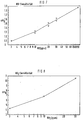
- Die folgenden Diagramme sollen die Empfindlichkeit bzw. Sensitivität der nach dem beschriebenen Verfahren hergestellten AlVO₄-Dünnschichten auf verschiedene Gase dokumentieren. Aufgetragen ist jeweils die Größe σ/σo (σo: Leitfähigkeit der sensitiven Schicht in synthetischer Luft (80 % N₂/20 % O₂)) in Abhängigkeit von der Zeit t bzw. der Konzentration des jeweiligen Gases.
- Bereits die Anwesenheit kleinster Mengen von Stickstoffmonoxid NO und Ammoniak NH₃ in trockener synthetischer Luft führt zu einem deutlichen Anstieg der Leitfähigkeit des Aluminiumvanadats AlVO₄ (s. Fig. 7 und 8). So ändert sich die Leitfähigkeit um etwa 75 %, wenn man der Luft 10 ppm Stickstoffmonoxid NO beimischt. Die Zugabe von 10 ppm Ammoniak NH₃ hat eine Erhöhung der Leitfähigkeit um mehr als ein Faktor 6 zur Folge.
- Wie die Fig. 9 zeigt, erhöht sich der spezifische Widerstand der AlVO₄-Dünnschicht bei Anwesenheit von Stickstoffdioxid NO₂. Da das Aluminiumvanadat gegenüber Stickstoffmonoxid NO ein völlig anderes Verhalten zeigt (Verringerung des spezifischen Widerstandes, s. Fig. 7), kann man beide Stickoxide eindeutig voneinander unterscheiden, sofern nur eines der beiden Stickoxide mit dem sensitiven Element wechselwirkt.
- Außer auf Stickstoffmonoxid NO und Ammoniak NH₃ spricht die Vanadatschicht auch auf Änderungen des Sauerstoffpartialdrucks und Wasserstoff H₂ an (s. Fig. 10). Die Querempfindlichkeit auf Sauerstoff O₂ und Wasserstoff H₂ ist allerdings erheblich kleiner als die Reaktion auf Stickstoffmonoxid NO und Ammoniak NH₃. So haben 500 ppm Wasserstoff H₂ in Luft annähernd dieselbe Änderung der Leitfähigkeit zur Folge wie die Zugabe von 10 ppm Stickstoffmonoxid NO. Nicht nachweisbar sind die Gase Kohlenmonoxid CO (bis 1500 ppm), Methan CH₄ (bis 5000 ppm) und Kohlendioxid CO₂ (bis 1 %) bis zu den in den Klammern jeweils angegebenen Konzentrationen. In einem feuchten Gasgemisch (80 mbar H₂O) beobachtet man eine deutliche Abnahme der NH₃-Sensitivität; sie bleibt aber immer noch doppelt so groß wie die Empfindlichkeit für Stickstoffmonoxid NO (s. den rechten Teil der Fig. 9).
- In Fig. 11 ist die Empfindlichkeit der AlVO₄-Dünnschicht in feuchter Luft (80 mbar H₂O) bei 500 °C und einem NO-Anteil von 10 ppm dargestellt. Innerhalb der jeweils durch eine waagrechte Linie markierten Zeitintervallen wurde der feuchten Luft ein weiteres Gas in der angegebenen Konzentration beigemischt. Die Luft enthielt also beispielsweise zwischen der 60. und der 120. Minute 1500 ppm Kohlenmonoxid CO und zwischen der 80. und der 100. Minute zusätzlich noch 10 ppm Stickstoffmonoxid NO. Wie die Meßergebnisse zeigen, wird die NO-Empfindlichkeit der AlVO₄-Schicht durch die Anwesenheit von Kohlenmonoxid CO, Methan CH₄ und Kohlendioxid CO₂ nicht beeinflußt. Die Beimischung von Wasserstoff H₂ bewirkt zwar keine Maskierung der NO-Sensitivität, es ist aber eine eindeutige Querempfindlichkeit festzustellen. Einen ähnlichen Effekt beobachtet man bei Sauerstoff O₂, wenn sich dessen Konzentration von 20 % auf 2 % verringert.
- Das in Fig. 12 dargestellte Edelstahlgehäuse dient dem Einbau des Detektors 9 in die Wandung des Abgasrohrs 4. Das Gehäuse besteht aus zwei Teilen, wobei der eine Gaseintrittsöffnung 24 und einen Metallsteg 25 aufweisende Gehäusekopf 26 auf dem mit einer Bohrung 27 zur Aufnahme des Detektors 9 versehenen Grundkörper 29 befestigt ist. Vor dem Verschweißen der beiden Teile 26 und 29 wird der Detektor 9 in der Bohrung 27 des Grundkörpers 29 verklebt. Nach der Montage befindet sich das sensitive Element in einem S-förmig gekrümmten Strömungskanal, der die Gaseintrittsöffnung 24 mit der Gasaustrittsöffnung 30 verbindet. Im linken Teil der Fig. 12 ist zusätzlich auch die die Bohrung 27 des unteren Gehäuseteils 29 abschließende Keramikplatte 31 gezeigt. Sie enthält mehrere Kanäle, durch die man die der Kontaktierung des Detektors 9 dienenden Anschlußdrähte 32 nach außen führt.
- Mit Hilfe des oben beschriebenen NO/NH₃-Detektors 9 läßt sich ein einfaches und effektives Verfahren zur Regelung der Harnstoffeinspritzung in den SCR-Katalysator 2 verwirklichen. Da der Detektor 9 sowohl auf Stickstoffmonoxid NO als auch auf Ammoniak NH₃ mit einer Erhöhung der Leitfähigkeit reagiert (vgl. die Fig. 7 und 8) kann man zunächst nicht entscheiden, welches der beiden Gase mit der sensitiven Schicht 12 wechselwirkt. Wie anhand des in Fig. 13 dargestellten Ablaufplans zu erkennen ist, wird die Steuereinheit 8 die Dosiereinrichtung 5 veranlassen, zunächst mehr Harnstoff in das Abgas einzuspritzen. Führt diese Maßnahme zu einer Erhöhung des Sensorwiderstands, so kann das Stickstoffmonoxid NO noch nicht vollständig zu Stickstoff N₂ und Wasser H₂O umgesetzt worden sein. Die eingespritzte Harnstoffmenge wird nun solange erhöht, bis der Sensorwiderstand den in Fig. 14 durch einen Pfeil gekennzeichneten Maximalwert erreicht und das den Katalysator 2 verlassende Abgas weder Stickstoffmonoxid NO noch überschüssiges Ammoniak NH₃ enthält.
- Führt die Mehreinspritzung von Harnstoff hingegen zu einem kleineren Sensorwiderstand, muß der NH₃-Überschuß im Abgas durch Verringerung der Harnstoffmenge abgebaut werden (s. rechter Teil des Ablaufplans). Im Diagramm der Fig. 14 nähert man sich dem die optimale Harnstoffmenge definierenden Maximalwert des Sensorwiderstands daher von rechts.
- Die Erfindung beschränkt sich selbstverständlich nicht auf die beschriebenen Ausführungsbeispiele. So ist es beispielsweise möglich, einen zweiten Detektor auf der Basis gesputterter Al₂O₃/V₂O₅-Schichten im Abgastrakt vor der Einspritzdüse 7 anzuordnen. Dieser Detektor dient dann vorzugsweise der Überwachung der beschriebenen Regelung, indem man die NO-Konzentration mißt und mit der jeweils eingespritzten Harnstoffmenge vergleicht. Die NH₃-Empfindlichkeit des Detektors wirkt sich hierbei nicht störend aus, da das Motorabgas vor der Einspritzdüse 7 kein Ammoniak NH₃ enthält.
- Als Reduktionsmittel kommen anstelle von Harnstoff auch Ammoniak in wässriger Lösung oder gasförmiges Ammoniak in Betracht, wobei man das Reduktionsmittel auch direkt in den SCR-Katalysator 2 einspritzen kann.
- Das erfindungsgemäße Verfahren läßt sich selbstverständlich auch in sogenannten DeNOx-Anlagen zur Rauchgasentstickung anwenden (s. beispielsweise /3/).
- /1/ Motortechnische Zeitschrift 49 (1988) 1, S. 17 bis 21
/2/ Motortechnische Zeitschrift 54 (1993) 6, S. 310 bis 315
/3/ Umwelt, 1986 No. 1, Fachreport Rauchgasreinigung, FR 19 bis FR 25
Claims (9)
- Verfahren zur Verminderung der Stickoxidkonzentration im Abgas einer Brennkraftmaschine oder einer Verbrennungsanlage bei dem dem Abgas ein ammoniakhaltiges Reduktionsmittel zugesetzt wird und bei dem Stickoxide in einer vom Abgas durchströmten Katalysatoreinheit (2) zu Stickstoff und Wasser umgesetzt werden,
dadurch gekennzeichnet,- daß ein sowohl auf Stickstoffmonoxid als auch auf Ammoniak ansprechendes erstes Sensorelement (12) im Abgasstrom hinter der Katalysatoreinheit (2) angeordnet wird,- daß der von der Stickstoffmonoxid- und Ammoniak-Konzentration abhängige Widerstand oder die elektrische Leitfähigkeit des Sensorelements (12) gemessen werden und- daß dem Abgas eine solche Menge des Reduktionsmittels zugesetzt wird, bei der der elektrische Widerstand des Sensorelements (12) am größten bzw. die elektrische Leitfähigkeit am kleinsten ist. - Verfahren nach Anspruch 1,
dadurch gekennzeichnet,
daß dem Abgas gasförmiges Ammoniak, Ammoniak in wässriger Lösung oder Harnstoff als Reduktionsmittel zugesetzt wird. - Verfahren nach Anspruch 1 oder 2,
dadurch gekennzeichnet,
daß der elektrische Widerstand oder die elektrische Leitfähigkeit eines aus einer Metalloxid-Vanadiumoxid-Mischung bestehenden Sensorelements (12) gemessen wird. - Verfahren nach Anspruch 3,
dadurch gekennzeichnet,
daß der elektrische Widerstand oder die elektrische Leitfähigkeit eines aus einer Aluminiumoxid-Vanadiumoxid-Mischung oder einer Eisenoxid-Vanadium-Mischung bestehenden Sensorelements (12) gemessen wird. - Verfahren nach einem der Ansprüche 1 bis 4,
dadurch gekennzeichnet,
daß der elektrische Widerstand oder die elektrische Leitfähigkeit eines aus einem Vanadat MeVO₄ bestehenden Sensorelements (12) gemessen wird, wobei Me ein dreiwertiges Metall bezeichnet.. - Verfahren nach Anspruch 5,
dadurch gekennzeichnet,
daß der elektrische Widerstand oder die elektrische Leitfähigkeit eines aus Aluminium- oder Eisenvanadat bestehenden Sensorelements (12) gemessen wird. - Verfahren nach einem der Ansprüche 1 bis 6,
dadurch gekennzeichnet,
daß ein schichtförmig ausgebildetes und durch ein Elektrodenpaar (11, 11') kontaktiertes Sensorelement (12) verwendet wird. - Verfahren nach einem der Ansprüche 1 bis 7,
dadurch gekennzeichnet,
daß das Sensorelement (12) aktiv beheizt und auf einer konstanten Temperatur gehalten wird. - Verfahren nach einem der Ansprüche 1 bis 8,
dadurch gekennzeichnet,
daß ein dem ersten Sensorelement (12) entsprechendes zweites Sensorelement im Abgasstrom vor der Katalysatoreinheit (2) angeordnet und zur Messung der Stickstoffmonoxid-Konzentration herangezogen wird.
Applications Claiming Priority (2)
| Application Number | Priority Date | Filing Date | Title |
|---|---|---|---|
| DE4334071A DE4334071C1 (de) | 1993-10-06 | 1993-10-06 | Verfahren zur Verminderung der Stickoxidkonzentration im Abgas einer Brennkraftmaschine oder einer Verbrennungsanlage |
| DE4334071 | 1993-10-06 |
Publications (2)
| Publication Number | Publication Date |
|---|---|
| EP0653237A1 true EP0653237A1 (de) | 1995-05-17 |
| EP0653237B1 EP0653237B1 (de) | 1996-12-27 |
Family
ID=6499545
Family Applications (1)
| Application Number | Title | Priority Date | Filing Date |
|---|---|---|---|
| EP94115280A Expired - Lifetime EP0653237B1 (de) | 1993-10-06 | 1994-09-28 | Verfahren zur Verminderung der Stickoxidkonzentration im Abgas einer Brennkraftmaschine oder einer Verbrennungsanlage |
Country Status (3)
| Country | Link |
|---|---|
| US (1) | US5540047A (de) |
| EP (1) | EP0653237B1 (de) |
| DE (2) | DE4334071C1 (de) |
Cited By (4)
| Publication number | Priority date | Publication date | Assignee | Title |
|---|---|---|---|---|
| EP0820799A3 (de) * | 1996-07-25 | 1998-08-12 | Ngk Insulators, Ltd. | System und Verfahren zur Entfernung von NOx aus Abgasen |
| NL1028497C2 (nl) * | 2005-03-09 | 2006-09-12 | Dsm Ip Assets Bv | Werkwijze voor de bereiding van een ureum-bevattende waterige stroom. |
| CN102027212B (zh) * | 2008-05-16 | 2014-01-29 | 标致·雪铁龙汽车公司 | 氮氧化物排放模型的校正方法 |
| EP3477068A4 (de) * | 2016-06-23 | 2020-07-29 | NGK Insulators, Ltd. | Abgasreinigungssystem und abgasreinigungsverfahren |
Families Citing this family (84)
| Publication number | Priority date | Publication date | Assignee | Title |
|---|---|---|---|---|
| ATE169130T1 (de) * | 1993-11-04 | 1998-08-15 | Siemens Ag | Verfahren und einrichtung zur dosierung eines reaktanten in ein strömungsmedium |
| DE19529835A1 (de) * | 1995-08-12 | 1997-02-13 | Opel Adam Ag | Abgasstrang eines Ottomotors |
| US6345496B1 (en) | 1995-11-09 | 2002-02-12 | Toyota Jidosha Kabushiki Kaisha | Method and device for purifying exhaust gas of an engine |
| EP0861367B1 (de) * | 1995-11-17 | 2000-08-16 | Toyota Jidosha Kabushiki Kaisha | Verfahren und vorrichtung zur reinigung von abgasen einer brennkraftmaschine |
| JP3713831B2 (ja) * | 1996-04-19 | 2005-11-09 | トヨタ自動車株式会社 | 内燃機関の排気浄化装置 |
| KR100290272B1 (ko) * | 1996-06-10 | 2001-05-15 | 가나이 쓰토무 | 내연기관의 배기 가스 정화 장치 및 내연기관의 배기 가스 정화촉매 |
| JP3454334B2 (ja) * | 1996-06-18 | 2003-10-06 | トヨタ自動車株式会社 | 排気浄化方法及びその装置 |
| HUP9800244A2 (hu) * | 1997-03-21 | 1999-06-28 | Von Roll Umwelttechnik Aktiengesellschaft | Eljárás és készülék egy kezelőanyag beadagolási mennyiségének szabályozására égésfolyamatok füstgázaiban a nitrogén-monoxid-tartalom csökkentésére |
| US6361754B1 (en) * | 1997-03-27 | 2002-03-26 | Clean Diesel Technologies, Inc. | Reducing no emissions from an engine by on-demand generation of ammonia for selective catalytic reduction |
| US5809775A (en) * | 1997-04-02 | 1998-09-22 | Clean Diesel Technologies, Inc. | Reducing NOx emissions from an engine by selective catalytic reduction utilizing solid reagents |
| EP0881367B1 (de) | 1997-05-30 | 2002-10-16 | Volkswagen Aktiengesellschaft | Katalysatorsystem zur Entstickung von Abgasen bei Dieselbrennkraftmaschinen |
| DE19727268C1 (de) * | 1997-06-26 | 1999-01-14 | Siemens Ag | Verfahren zur Überwachung der Reduktionsmitteldosierung bei einem SCR-Katalysator |
| DE19736384A1 (de) * | 1997-08-21 | 1999-02-25 | Man Nutzfahrzeuge Ag | Verfahren zur Dosierung eines Reduktionsmittels in stickoxidhaltiges Abgas einer Brennkraftmaschine |
| DE19749400C2 (de) | 1997-11-07 | 2001-11-29 | Siemens Ag | Verfahren zur Verringerung des NOX-Gehaltes im Abgas einer Dieselbrennkraftmaschine |
| DE19756251C1 (de) * | 1997-12-17 | 1999-07-22 | Siemens Ag | Verfahren und Vorrichtung zur Reduzierung der Stickoxide im Abgas einer Verbrennungsanlage |
| DE19807935C1 (de) | 1998-02-25 | 1999-08-26 | Siemens Ag | Vorrichtung zur Reduzierung des NO¶x¶-Gehaltes im Abgas einer Brennkraftmaschine |
| DE19808382A1 (de) * | 1998-02-27 | 1999-09-02 | Volkswagen Ag | Steuerung eines NOx-Absorber-Katalysator |
| DE19823923C2 (de) * | 1998-05-28 | 2003-04-17 | Siemens Ag | Verfahren zur Stickoxidreduzierung im Abgas einer Brennkraftmaschine |
| DE19846487C5 (de) * | 1998-10-09 | 2004-12-30 | Basf Ag | Meßsonde für die Detektion der Momentankonzentrationen mehrerer Gasbestandteile eines Gases |
| DE19852244C1 (de) * | 1998-11-12 | 1999-12-30 | Siemens Ag | Verfahren und Vorrichtung zur Abgasreinigung mit Trimmregelung |
| DE19856369C2 (de) * | 1998-12-07 | 2000-12-07 | Siemens Ag | Resistiver Gassensor und Verfahren zu dessen Herstellung |
| DE19901915C1 (de) * | 1999-01-19 | 2000-04-20 | Siemens Ag | Verfahren zur katalytischen Umsetzung von im Abgas eines Verbrennungsmotors enthaltenen Stickoxiden |
| DE19907669C1 (de) * | 1999-02-23 | 2000-11-30 | Daimler Chrysler Ag | Verfahren zur Korrektur des Wassereinflusses auf das Signal eines Sensors zur Detektion der im Abgas eines Verbrennungsmotors befindlichen Reduktionsmittelkonzentration |
| DE19919472C2 (de) * | 1999-04-29 | 2001-04-19 | Bosch Gmbh Robert | Vorrichtung und Verfahren zur Detektion von Ammoniak |
| US6305160B1 (en) | 1999-07-12 | 2001-10-23 | Ford Global Technologies, Inc. | Emission control system |
| US6295809B1 (en) | 1999-07-12 | 2001-10-02 | Ford Global Technologies, Inc. | Emission control system with a catalyst |
| US6266955B1 (en) | 1999-08-20 | 2001-07-31 | Caterpillar Inc. | Diagnostic system for an emissions control on an engine |
| US6440382B1 (en) * | 1999-08-31 | 2002-08-27 | Micron Technology, Inc. | Method for producing water for use in manufacturing semiconductors |
| US7871598B1 (en) | 2000-05-10 | 2011-01-18 | Novartis Ag | Stable metal ion-lipid powdered pharmaceutical compositions for drug delivery and methods of use |
| EP1164266B1 (de) * | 2000-06-13 | 2009-10-07 | Ford Global Technologies, Inc. | Verfahren zur Optimierung der Zugabe eines Reduktionmittels zu einem SCR-Katalysator einer Brennkraftmaschine |
| US6427439B1 (en) | 2000-07-13 | 2002-08-06 | Ford Global Technologies, Inc. | Method and system for NOx reduction |
| US6526746B1 (en) * | 2000-08-02 | 2003-03-04 | Ford Global Technologies, Inc. | On-board reductant delivery assembly |
| US6740597B1 (en) * | 2000-08-31 | 2004-05-25 | Micron Technology, Inc. | Methods of removing at least some of a material from a semiconductor substrate |
| EP1209120A3 (de) * | 2000-11-24 | 2004-02-04 | Herbert Wancura | Verfahren und Vorrichtung zur Herstellung von Brenngas |
| US6625977B2 (en) | 2000-12-20 | 2003-09-30 | Caterpillar Inc | Method and a system for removing particulates and toxic substances from an exhaust of an engine that use hydrocarbons as a fuel |
| DE10102237A1 (de) * | 2001-01-19 | 2002-08-08 | Bosch Gmbh Robert | Vorrichtung zur Dosierung einer Harnstofflösung |
| US6449945B1 (en) | 2001-04-18 | 2002-09-17 | Ford Global Technologies, Inc. | Emission control system |
| US6594985B2 (en) * | 2001-06-19 | 2003-07-22 | Ford Global Technologies, Inc. | Exhaust gas aftertreatment device efficiency estimation |
| US6650991B2 (en) * | 2001-06-19 | 2003-11-18 | Ford Global Technologies, Llc | Closed-loop method and system for purging a vehicle emission control |
| US6742326B2 (en) | 2001-08-09 | 2004-06-01 | Ford Global Technologies, Llc | High efficiency conversion of nitrogen oxides in an exhaust aftertreatment device at low temperature |
| US6421599B1 (en) | 2001-08-09 | 2002-07-16 | Ford Global Technologies, Inc. | Control strategy for an internal combustion engine in a hybrid vehicle |
| US6698191B2 (en) | 2001-08-09 | 2004-03-02 | Ford Global Technologies, Llc | High efficiency conversion of nitrogen oxides in an exhaust aftertreatment device at low temperature |
| US6928359B2 (en) | 2001-08-09 | 2005-08-09 | Ford Global Technologies, Llc | High efficiency conversion of nitrogen oxides in an exhaust aftertreatment device at low temperature |
| DE10142236A1 (de) * | 2001-08-29 | 2003-04-10 | Conti Temic Microelectronic | Verfahren zum Bestimmen der Reduktionsmittelkonzentration (NH3) im Abgasstrom eines Verbrennungsmotors |
| GB2382657A (en) * | 2001-09-04 | 2003-06-04 | Ford Global Tech Inc | A method and apparatus for determining if a sensor is responding to a first substance or a second substance |
| US7121085B2 (en) | 2001-09-04 | 2006-10-17 | Ford Global Technologies, Llc | Method and apparatus for controlling hydrocarbon injection into engine exhaust to reduce NOx |
| US6487852B1 (en) | 2001-09-04 | 2002-12-03 | Ford Global Technologies, Inc. | Method and apparatus for controlling reactant injection into an active lean NOx catalyst |
| US6546720B2 (en) * | 2001-09-04 | 2003-04-15 | Ford Global Technologies, Inc. | Method and apparatus for controlling the amount of reactant to be added to a substance using a sensor which is responsive to both the reactant and the substance |
| DE10207984A1 (de) * | 2002-02-25 | 2003-10-23 | Daimler Chrysler Ag | Vorrichtung zur Abgasreinigung und Verfahren hierzu |
| US7497076B2 (en) * | 2002-05-07 | 2009-03-03 | Extengine Transport Systems | Emission control system |
| AU2003273138A1 (en) * | 2002-05-07 | 2003-12-12 | Extengine Transport Systems | Emission control system |
| US20040126286A1 (en) * | 2002-06-19 | 2004-07-01 | Deruyter John C. | Method and apparatus for reducing a nitrogen oxide |
| US7575931B2 (en) * | 2002-06-19 | 2009-08-18 | E.I. Du Pont De Nemours And Company | Method and apparatus for reducing a nitrogen oxide, and control thereof |
| US6887284B2 (en) * | 2002-07-12 | 2005-05-03 | Dannie B. Hudson | Dual homogenization system and process for fuel oil |
| US6941746B2 (en) * | 2002-11-21 | 2005-09-13 | Combustion Components Associates, Inc. | Mobile diesel selective catalytic reduction systems and methods |
| US6834498B2 (en) * | 2002-11-21 | 2004-12-28 | Ford Global Technologies, Llc | Diesel aftertreatment systems |
| US6895747B2 (en) | 2002-11-21 | 2005-05-24 | Ford Global Technologies, Llc | Diesel aftertreatment systems |
| US6862879B2 (en) | 2002-11-21 | 2005-03-08 | Ford Global Technologies, Llc | Diesel aftertreatment system |
| US6761025B1 (en) | 2002-12-19 | 2004-07-13 | Caterpillar Inc. | Enhanced ammonia feed control for selective catalytic reduction |
| SE0303201D0 (sv) * | 2003-09-09 | 2003-11-25 | Volvo Lastvagnar Ab | Förbränningsmotor av kolvtyp och metod att styra densamma |
| US7776265B2 (en) * | 2004-03-18 | 2010-08-17 | Cummins Filtration Ip, Inc. | System for diagnosing reagent solution quality |
| DE102004046639A1 (de) * | 2004-09-25 | 2006-03-30 | Robert Bosch Gmbh | Verfahren zum Betreiben einer Brennkraftmaschine und Vorrichtung zur Durchführung des Verfahrens |
| SE0402499L (sv) | 2004-10-13 | 2006-02-21 | Volvo Lastvagnar Ab | Motordrivet fordon och metod med fragmenterad insprutning av kolväten för optimerad oxidering av kvävemonoxid i avgasefterbehandlingssystem |
| US20060248876A1 (en) * | 2005-05-04 | 2006-11-09 | Taxon Morse N | Selective catalytic reduction exhaust after-treatment |
| CN100587235C (zh) * | 2005-09-29 | 2010-02-03 | 沃尔沃拉斯特瓦格纳公司 | 用于排气后处理系统的诊断方法 |
| DE102006021089B4 (de) * | 2006-05-05 | 2009-11-12 | Continental Automotive Gmbh | Verfahren und Vorrichtung zum Betreiben einer Brennkraftmaschine |
| US7426825B2 (en) * | 2006-07-25 | 2008-09-23 | Gm Global Technology Operations, Inc. | Method and apparatus for urea injection in an exhaust aftertreatment system |
| EP1884772A1 (de) * | 2006-08-02 | 2008-02-06 | Nederlandse Organisatie voor Toegepast-Natuuurwetenschappelijk Onderzoek TNO | Qualitätskontrolle selektiver katalytischer Reduktionsreagenzien |
| DE112007003583A5 (de) * | 2007-09-18 | 2010-07-29 | Fev Motorentechnik Gmbh | NH3-Überwachung eines SCR-Katalysators |
| DE102007044610B4 (de) * | 2007-09-19 | 2010-04-08 | Continental Automotive Gmbh | Verfahren zur Detektion der minimalen Öffnungszeit einer Reduktionsmittelzuführeinrichtung in einem Abgasnachbehandlungssystem mit einem SCR-Katalysator |
| US7736608B2 (en) * | 2007-11-29 | 2010-06-15 | General Electric Company | Methods and systems for reducing the emissions from combustion gases |
| FR2926592B1 (fr) * | 2008-01-18 | 2012-07-13 | Peugeot Citroen Automobiles Sa | Procede d'injection d'agent reducteur dans une ligne d'echappement |
| US7856807B2 (en) * | 2008-03-17 | 2010-12-28 | Cummins Filtration Ip, Inc. | Flow reversal chambers for increased residence time |
| US8071037B2 (en) | 2008-06-25 | 2011-12-06 | Cummins Filtration Ip, Inc. | Catalytic devices for converting urea to ammonia |
| DE102008064606B4 (de) * | 2008-12-19 | 2020-03-05 | Volkswagen Ag | Funktionsanpassung einer Abgasreinigungsvorrichtung |
| FR2949812B1 (fr) * | 2009-09-10 | 2012-03-30 | Peugeot Citroen Automobiles Sa | Dispositif et procede de regulation de l'injection d'une quantite de reducteur en phase gaz |
| TWI498158B (zh) * | 2010-04-16 | 2015-09-01 | Treibacher Ind Ag | 用於廢氣之選擇性催化還原反應的觸媒組成物 |
| EP2665902B1 (de) * | 2011-01-18 | 2018-11-07 | Stant USA Corp. | Entlüftungsanlage für einen dieselabgasflüssigkeitstank |
| DE102013108505A1 (de) * | 2013-08-07 | 2015-03-05 | Emitec Denmark A/S | Verfahren zum Bestimmen der Qualität von Reduktionsmittel |
| US9695727B2 (en) | 2015-09-02 | 2017-07-04 | Deere & Company | System and method for adaptive aftertreatment control of NOx |
| JP6730069B2 (ja) * | 2016-04-14 | 2020-07-29 | ローム株式会社 | 窒素酸化物系ガスセンサ、および酸素ポンプ |
| JP7074014B2 (ja) * | 2018-10-17 | 2022-05-24 | トヨタ自動車株式会社 | ガス分離システム |
| US11732628B1 (en) | 2020-08-12 | 2023-08-22 | Old World Industries, Llc | Diesel exhaust fluid |
| CN115616059B (zh) * | 2022-10-17 | 2026-04-21 | 凯龙高科技股份有限公司 | 一种用于氨氮气体检测的气体传感器及其制备方法 |
Citations (8)
| Publication number | Priority date | Publication date | Assignee | Title |
|---|---|---|---|---|
| JPS53129098A (en) * | 1977-04-18 | 1978-11-10 | Hitachi Ltd | Gas sensor material |
| JPS6383652A (ja) * | 1986-09-29 | 1988-04-14 | Toshiba Corp | ガスセンサ |
| US4751054A (en) * | 1985-07-16 | 1988-06-14 | Babcock - Hitachi Kabushiki Kaisha | Apparatus for removing NOx from a gas |
| EP0362483A1 (de) * | 1988-07-25 | 1990-04-11 | Degussa Aktiengesellschaft | Verfahren zur katalytischen Entstickung von Abgasen mittels eines Reduktionsmittels |
| WO1991019975A1 (en) * | 1990-06-12 | 1991-12-26 | Catalytica, Inc. | NOx SENSOR ASSEMBLY |
| JPH0429049A (ja) * | 1990-05-25 | 1992-01-31 | Toto Ltd | アンモニアガスセンサ |
| DE4217552C1 (de) * | 1992-05-27 | 1993-08-19 | Mercedes-Benz Aktiengesellschaft, 7000 Stuttgart, De | |
| DE4227741A1 (de) * | 1992-08-21 | 1994-02-24 | Bayerische Motoren Werke Ag | Verfahren zur Reduktion von in Abgasen enthaltenen Stickoxiden |
Family Cites Families (5)
| Publication number | Priority date | Publication date | Assignee | Title |
|---|---|---|---|---|
| DE3606535A1 (de) * | 1986-02-28 | 1987-09-03 | Kloeckner Humboldt Deutz Ag | Verfahren und vorrichtung zur verminderung von stickoxiden in abgasen |
| DE3610364A1 (de) * | 1986-03-27 | 1987-10-01 | Kernforschungsz Karlsruhe | Verfahren zum verringern des no(pfeil abwaerts)x(pfeil abwaerts)-gehaltes in gasen, bei welchem dem gaststrom kontinuierlich nh(pfeil abwaerts)3(pfeil abwaerts) zugesetzt wird |
| JP3375645B2 (ja) * | 1991-05-14 | 2003-02-10 | 株式会社日立製作所 | 内燃機関の制御装置 |
| WO1992021871A1 (fr) * | 1991-06-03 | 1992-12-10 | Isuzu Motors Limited | DISPOSITIF POUR LA REDUCTION DU NO¿x? |
| US5367875A (en) * | 1992-12-07 | 1994-11-29 | Coltec Industries Inc | Automated catalytic reduction system |
-
1993
- 1993-10-06 DE DE4334071A patent/DE4334071C1/de not_active Expired - Fee Related
-
1994
- 1994-09-28 DE DE59401394T patent/DE59401394D1/de not_active Expired - Fee Related
- 1994-09-28 EP EP94115280A patent/EP0653237B1/de not_active Expired - Lifetime
- 1994-10-06 US US08/319,290 patent/US5540047A/en not_active Expired - Lifetime
Patent Citations (8)
| Publication number | Priority date | Publication date | Assignee | Title |
|---|---|---|---|---|
| JPS53129098A (en) * | 1977-04-18 | 1978-11-10 | Hitachi Ltd | Gas sensor material |
| US4751054A (en) * | 1985-07-16 | 1988-06-14 | Babcock - Hitachi Kabushiki Kaisha | Apparatus for removing NOx from a gas |
| JPS6383652A (ja) * | 1986-09-29 | 1988-04-14 | Toshiba Corp | ガスセンサ |
| EP0362483A1 (de) * | 1988-07-25 | 1990-04-11 | Degussa Aktiengesellschaft | Verfahren zur katalytischen Entstickung von Abgasen mittels eines Reduktionsmittels |
| JPH0429049A (ja) * | 1990-05-25 | 1992-01-31 | Toto Ltd | アンモニアガスセンサ |
| WO1991019975A1 (en) * | 1990-06-12 | 1991-12-26 | Catalytica, Inc. | NOx SENSOR ASSEMBLY |
| DE4217552C1 (de) * | 1992-05-27 | 1993-08-19 | Mercedes-Benz Aktiengesellschaft, 7000 Stuttgart, De | |
| DE4227741A1 (de) * | 1992-08-21 | 1994-02-24 | Bayerische Motoren Werke Ag | Verfahren zur Reduktion von in Abgasen enthaltenen Stickoxiden |
Non-Patent Citations (4)
| Title |
|---|
| DATABASE WPI Section Ch Week 7850, Derwent World Patents Index; Class E31, AN 78-90665A * |
| DATABASE WPI Section Ch Week 8821, Derwent World Patents Index; Class J04, AN 88-142900 * |
| DATABASE WPI Section Ch Week 9211, Derwent World Patents Index; Class E35, AN 92-085478 * |
| TATSUMI ISHIHARA ET AL.: "The Mixed Oxide Al2O3-V2O5 as a Semiconductor Gas Sensor for NO and NO2", SENSORS AND ACTUATORS, vol. 19, no. 3, September 1989 (1989-09-01), LAUSANNE CH, pages 259 - 265, XP000047321 * |
Cited By (6)
| Publication number | Priority date | Publication date | Assignee | Title |
|---|---|---|---|---|
| EP0820799A3 (de) * | 1996-07-25 | 1998-08-12 | Ngk Insulators, Ltd. | System und Verfahren zur Entfernung von NOx aus Abgasen |
| US6017503A (en) * | 1996-07-25 | 2000-01-25 | Ngk Insulators, Ltd. | Method of removing NOx from exhaust gases |
| US6455009B1 (en) | 1996-07-25 | 2002-09-24 | Ngk Insulators, Ltd. | System for removing NOx from exhaust gases |
| NL1028497C2 (nl) * | 2005-03-09 | 2006-09-12 | Dsm Ip Assets Bv | Werkwijze voor de bereiding van een ureum-bevattende waterige stroom. |
| CN102027212B (zh) * | 2008-05-16 | 2014-01-29 | 标致·雪铁龙汽车公司 | 氮氧化物排放模型的校正方法 |
| EP3477068A4 (de) * | 2016-06-23 | 2020-07-29 | NGK Insulators, Ltd. | Abgasreinigungssystem und abgasreinigungsverfahren |
Also Published As
| Publication number | Publication date |
|---|---|
| EP0653237B1 (de) | 1996-12-27 |
| US5540047A (en) | 1996-07-30 |
| DE59401394D1 (de) | 1997-02-06 |
| DE4334071C1 (de) | 1995-02-09 |
Similar Documents
| Publication | Publication Date | Title |
|---|---|---|
| EP0653237B1 (de) | Verfahren zur Verminderung der Stickoxidkonzentration im Abgas einer Brennkraftmaschine oder einer Verbrennungsanlage | |
| DE69117289T2 (de) | Stickoxyd-sensoraufbau | |
| EP0604468B1 (de) | Abgassensor | |
| EP2226480B1 (de) | Verfahren zur Einstellung der Dosierungen des Reduktionsmittels bei selektiver katalytischer Reduktion | |
| EP2226482B1 (de) | Verfahren zur Anpassung der Dosiermenge eines Reduktionsmittels zur selektiven katalytischen Reduktion | |
| DE69124603T2 (de) | Stickoxydsensor und verfahren zur feststellung von stickoxyd | |
| EP1338770A2 (de) | Abgasreinigungsanlage für eine Brennkraftmaschine | |
| DE102008036884A1 (de) | Verfahren zum Betreiben einer Abgasreinigungsanlage mit einem SCR-Katalysator | |
| DE19846487C2 (de) | Meßsonde für die Detektion der Momentankonzentrationen mehrerer Gasbestandteile eines Gases | |
| WO2007110258A1 (de) | Ammoniaksensor | |
| EP0652435A2 (de) | Sensor zur Bestimmung des Verlaufs der Konzentration | |
| WO2001064319A1 (de) | Verfahren und abgasreinigungsanlage zur katalytischen reduktion von stickoxiden im abgas einer verbrennungsanlage | |
| DE19856369C2 (de) | Resistiver Gassensor und Verfahren zu dessen Herstellung | |
| DE4333006C2 (de) | Detektor zum Nachweis von Stickstoffmonoxid NO und Ammoniak NH3 | |
| EP3814763A1 (de) | Verfahren zur messung von stickoxiden und vorrichtung zur durchführung des verfahrens | |
| DD296617A5 (de) | Katalysator zur reinigung von abgasen aus ueberstaechiometrisch betriebenen verbrennungsmotoren und gasturbinen | |
| DE112019002670T5 (de) | Verschlechterungsbestimmungsgerät für einen Ammoniaksensor | |
| DE102019114997A1 (de) | Verfahren und system zur steuerung der einspritzung eines reduktionsmittels in einen abgasstrom | |
| EP1389268B1 (de) | Sensor und verfahren zur überwachung und steuerung von katalysatoren, insbesondere von kraftfahrzeugkatalysatoren | |
| DE102010023523A1 (de) | Vorrichtung und Verfahren zur Detektion einer Menge einer Gaskomponente | |
| EP2184601B1 (de) | Sensorvorrichtung zum Messen einer Ammoniakkonzentration | |
| DE3610364A1 (de) | Verfahren zum verringern des no(pfeil abwaerts)x(pfeil abwaerts)-gehaltes in gasen, bei welchem dem gaststrom kontinuierlich nh(pfeil abwaerts)3(pfeil abwaerts) zugesetzt wird | |
| EP3899520B1 (de) | Verfahren zur verringerung von messfehlern bei der erfassung von ammoniak beim betreiben eines sensorsystems | |
| WO2010015490A1 (de) | Widerstandsgassensor für die bestimmung eines reduzierbaren gases | |
| EP0871031A2 (de) | Verfahren zum NO-Nachweis in fluiden Medien |
Legal Events
| Date | Code | Title | Description |
|---|---|---|---|
| PUAI | Public reference made under article 153(3) epc to a published international application that has entered the european phase |
Free format text: ORIGINAL CODE: 0009012 |
|
| AK | Designated contracting states |
Kind code of ref document: A1 Designated state(s): CH DE FR IT LI NL SE |
|
| 17P | Request for examination filed |
Effective date: 19950607 |
|
| GRAG | Despatch of communication of intention to grant |
Free format text: ORIGINAL CODE: EPIDOS AGRA |
|
| 17Q | First examination report despatched |
Effective date: 19960206 |
|
| GRAH | Despatch of communication of intention to grant a patent |
Free format text: ORIGINAL CODE: EPIDOS IGRA |
|
| GRAH | Despatch of communication of intention to grant a patent |
Free format text: ORIGINAL CODE: EPIDOS IGRA |
|
| GRAA | (expected) grant |
Free format text: ORIGINAL CODE: 0009210 |
|
| AK | Designated contracting states |
Kind code of ref document: B1 Designated state(s): CH DE FR IT LI NL SE |
|
| REG | Reference to a national code |
Ref country code: CH Ref legal event code: NV Representative=s name: SIEMENS SCHWEIZ AG |
|
| REF | Corresponds to: |
Ref document number: 59401394 Country of ref document: DE Date of ref document: 19970206 |
|
| ET | Fr: translation filed | ||
| ITF | It: translation for a ep patent filed | ||
| PLBQ | Unpublished change to opponent data |
Free format text: ORIGINAL CODE: EPIDOS OPPO |
|
| PLBI | Opposition filed |
Free format text: ORIGINAL CODE: 0009260 |
|
| PLBF | Reply of patent proprietor to notice(s) of opposition |
Free format text: ORIGINAL CODE: EPIDOS OBSO |
|
| 26 | Opposition filed |
Opponent name: HERAEUS SENSOR GMBH Effective date: 19970925 |
|
| NLR1 | Nl: opposition has been filed with the epo |
Opponent name: HERAEUS SENSOR GMBH |
|
| PLBF | Reply of patent proprietor to notice(s) of opposition |
Free format text: ORIGINAL CODE: EPIDOS OBSO |
|
| PLBO | Opposition rejected |
Free format text: ORIGINAL CODE: EPIDOS REJO |
|
| PLBN | Opposition rejected |
Free format text: ORIGINAL CODE: 0009273 |
|
| STAA | Information on the status of an ep patent application or granted ep patent |
Free format text: STATUS: OPPOSITION REJECTED |
|
| 27O | Opposition rejected |
Effective date: 19980412 |
|
| NLR2 | Nl: decision of opposition | ||
| PGFP | Annual fee paid to national office [announced via postgrant information from national office to epo] |
Ref country code: CH Payment date: 20030923 Year of fee payment: 10 |
|
| PG25 | Lapsed in a contracting state [announced via postgrant information from national office to epo] |
Ref country code: LI Free format text: LAPSE BECAUSE OF NON-PAYMENT OF DUE FEES Effective date: 20040930 Ref country code: CH Free format text: LAPSE BECAUSE OF NON-PAYMENT OF DUE FEES Effective date: 20040930 |
|
| REG | Reference to a national code |
Ref country code: CH Ref legal event code: PL |
|
| PGFP | Annual fee paid to national office [announced via postgrant information from national office to epo] |
Ref country code: NL Payment date: 20080915 Year of fee payment: 15 Ref country code: IT Payment date: 20080922 Year of fee payment: 15 Ref country code: FR Payment date: 20080912 Year of fee payment: 15 |
|
| PGFP | Annual fee paid to national office [announced via postgrant information from national office to epo] |
Ref country code: DE Payment date: 20080919 Year of fee payment: 15 |
|
| PGFP | Annual fee paid to national office [announced via postgrant information from national office to epo] |
Ref country code: SE Payment date: 20080912 Year of fee payment: 15 |
|
| EUG | Se: european patent has lapsed | ||
| REG | Reference to a national code |
Ref country code: NL Ref legal event code: V1 Effective date: 20100401 |
|
| REG | Reference to a national code |
Ref country code: FR Ref legal event code: ST Effective date: 20100531 |
|
| PG25 | Lapsed in a contracting state [announced via postgrant information from national office to epo] |
Ref country code: FR Free format text: LAPSE BECAUSE OF NON-PAYMENT OF DUE FEES Effective date: 20090930 Ref country code: DE Free format text: LAPSE BECAUSE OF NON-PAYMENT OF DUE FEES Effective date: 20100401 |
|
| PG25 | Lapsed in a contracting state [announced via postgrant information from national office to epo] |
Ref country code: NL Free format text: LAPSE BECAUSE OF NON-PAYMENT OF DUE FEES Effective date: 20100401 |
|
| PG25 | Lapsed in a contracting state [announced via postgrant information from national office to epo] |
Ref country code: IT Free format text: LAPSE BECAUSE OF NON-PAYMENT OF DUE FEES Effective date: 20090928 |
|
| PG25 | Lapsed in a contracting state [announced via postgrant information from national office to epo] |
Ref country code: SE Free format text: LAPSE BECAUSE OF NON-PAYMENT OF DUE FEES Effective date: 20090929 |