EP0653272B1 - Abnehmbarer Schutz für ein Pistolenförmiges Werkzeug - Google Patents
Abnehmbarer Schutz für ein Pistolenförmiges Werkzeug Download PDFInfo
- Publication number
- EP0653272B1 EP0653272B1 EP94307750A EP94307750A EP0653272B1 EP 0653272 B1 EP0653272 B1 EP 0653272B1 EP 94307750 A EP94307750 A EP 94307750A EP 94307750 A EP94307750 A EP 94307750A EP 0653272 B1 EP0653272 B1 EP 0653272B1
- Authority
- EP
- European Patent Office
- Prior art keywords
- cover
- halves
- handle
- grooves
- gun
- Prior art date
- Legal status (The legal status is an assumption and is not a legal conclusion. Google has not performed a legal analysis and makes no representation as to the accuracy of the status listed.)
- Expired - Lifetime
Links
- 239000007921 spray Substances 0.000 claims description 25
- 239000003973 paint Substances 0.000 claims description 10
- 239000012530 fluid Substances 0.000 claims description 6
- 230000037431 insertion Effects 0.000 claims 2
- 238000003780 insertion Methods 0.000 claims 2
- 230000000717 retained effect Effects 0.000 abstract 1
- 238000004140 cleaning Methods 0.000 description 5
- 230000007246 mechanism Effects 0.000 description 5
- 239000004033 plastic Substances 0.000 description 4
- 229920003023 plastic Polymers 0.000 description 4
- 239000002904 solvent Substances 0.000 description 3
- 238000005507 spraying Methods 0.000 description 3
- 239000000463 material Substances 0.000 description 2
- 238000000034 method Methods 0.000 description 2
- 238000010276 construction Methods 0.000 description 1
- 230000008030 elimination Effects 0.000 description 1
- 238000003379 elimination reaction Methods 0.000 description 1
- 239000002184 metal Substances 0.000 description 1
- 238000007493 shaping process Methods 0.000 description 1
- 239000007787 solid Substances 0.000 description 1
- 230000001960 triggered effect Effects 0.000 description 1
- 239000002023 wood Substances 0.000 description 1
Images


Classifications
-
- B—PERFORMING OPERATIONS; TRANSPORTING
- B05—SPRAYING OR ATOMISING IN GENERAL; APPLYING FLUENT MATERIALS TO SURFACES, IN GENERAL
- B05B—SPRAYING APPARATUS; ATOMISING APPARATUS; NOZZLES
- B05B15/00—Details of spraying plant or spraying apparatus not otherwise provided for; Accessories
- B05B15/60—Arrangements for mounting, supporting or holding spraying apparatus
- B05B15/63—Handgrips
-
- B—PERFORMING OPERATIONS; TRANSPORTING
- B05—SPRAYING OR ATOMISING IN GENERAL; APPLYING FLUENT MATERIALS TO SURFACES, IN GENERAL
- B05B—SPRAYING APPARATUS; ATOMISING APPARATUS; NOZZLES
- B05B15/00—Details of spraying plant or spraying apparatus not otherwise provided for; Accessories
-
- B—PERFORMING OPERATIONS; TRANSPORTING
- B05—SPRAYING OR ATOMISING IN GENERAL; APPLYING FLUENT MATERIALS TO SURFACES, IN GENERAL
- B05B—SPRAYING APPARATUS; ATOMISING APPARATUS; NOZZLES
- B05B12/00—Arrangements for controlling delivery; Arrangements for controlling the spray area
- B05B12/16—Arrangements for controlling delivery; Arrangements for controlling the spray area for controlling the spray area
- B05B12/20—Masking elements, i.e. elements defining uncoated areas on an object to be coated
- B05B12/22—Masking elements, i.e. elements defining uncoated areas on an object to be coated movable relative to the spray area
-
- B—PERFORMING OPERATIONS; TRANSPORTING
- B08—CLEANING
- B08B—CLEANING IN GENERAL; PREVENTION OF FOULING IN GENERAL
- B08B17/00—Methods preventing fouling
- B08B17/02—Preventing deposition of fouling or of dust
- B08B17/04—Preventing deposition of fouling or of dust by using removable coverings
-
- B—PERFORMING OPERATIONS; TRANSPORTING
- B25—HAND TOOLS; PORTABLE POWER-DRIVEN TOOLS; MANIPULATORS
- B25F—COMBINATION OR MULTI-PURPOSE TOOLS NOT OTHERWISE PROVIDED FOR; DETAILS OR COMPONENTS OF PORTABLE POWER-DRIVEN TOOLS NOT PARTICULARLY RELATED TO THE OPERATIONS PERFORMED AND NOT OTHERWISE PROVIDED FOR
- B25F5/00—Details or components of portable power-driven tools not particularly related to the operations performed and not otherwise provided for
- B25F5/006—Vibration damping means
-
- B—PERFORMING OPERATIONS; TRANSPORTING
- B25—HAND TOOLS; PORTABLE POWER-DRIVEN TOOLS; MANIPULATORS
- B25F—COMBINATION OR MULTI-PURPOSE TOOLS NOT OTHERWISE PROVIDED FOR; DETAILS OR COMPONENTS OF PORTABLE POWER-DRIVEN TOOLS NOT PARTICULARLY RELATED TO THE OPERATIONS PERFORMED AND NOT OTHERWISE PROVIDED FOR
- B25F5/00—Details or components of portable power-driven tools not particularly related to the operations performed and not otherwise provided for
- B25F5/02—Construction of casings, bodies or handles
Definitions
- the invention relates to a body and handle cover for a gun shaped tool according to the pre-characterising portion of claim 1, and more particularly to a removable cover for a spray gun.
- a removable cover of the type described in the pre-characterising portion of claim 1 is known from US-A-3799447.
- Paint spray guns are most commonly provided with a solid metal body and an integral handle which are bored out to form paint and air passages and chambers for a triggering mechanism and for seals. During use, paint may accumulate on the exterior of the gun. Cleaning the exterior of the gun may necessitate submersion of the entire gun in solvent. It may be necessary to partially disassemble the gun to remove trapped solvent after cleaning.
- Some spray guns are provided with a plastic cover which encloses a frame including a body, a handle and a portion of the trigger mechanism. The cover is secured with screws set into recessed cavities in the cover. The cover can be removed from the frame to facilitate cleaning. Once removed, the cover is easily cleaned without having to submerge the entire gun in solvent and, once cleaned, the cover is easily dried.
- US-A-3006560 discloses a spray gun having a two piece plastics cover which is secured to the handle by the combination of a recess provided on the handle into which an end of each piece of the plastics cover is received and by pins or screws received in holes in the cover and handle. Removing a number of screws may be time consuming and there is a risk that the small screws will be lost. On spray guns and other tools, ease of cleaning and servicing with a minimum of tools is a valued product feature.
- Providing a removable cover on a hand tool has an additional advantage. Tools are sometimes accidentally dropped or otherwise damaged during use. If the cover is damaged, it may be replaced. If the tool has no replaceable cover, it is necessary to construct the tool from stronger, heavier materials to reduce the risk of damage. This increases the weight of the tool which in turn increases operator fatigue during use.
- the present invention provides a removable cover for a gun shaped tool having a body and a handle extending from the body, comprising first and second cover halves, said cover halves having a shape and size for enclosing at least a portion of the tool body and handle when said halves are positioned together characterised in that each of said cover halves has tab means projecting from a front end portion for engaging a notch on the tool for securing said front end portions of said cover to the tool, each of said cover halves has a first groove adjacent a rear portion and a second groove adjacent an end of the handle portion, and first spring clip means is provided for positioning in said first grooves and adapted for securing the rear cover portions together, and second spring clip means is provided for positioning in said second grooves and adapted for securing together said cover handle portions.
- the invention is directed to an improved removable cover for enclosing at least a portion of a frame of a gun shaped tool, such as a paint spray gun.
- frame is intended to mean an upper body, a depending handle and any attached mechanism for operating the tool.
- the body portion of the frame has front and rear ends.
- the handle typically depends from adjacent a rear end of the body.
- the cover is formed into two halves for enclosing opposite sides of the frame. When the cover halves are positioned together, they form an enclosed chamber for receiving the frame and are shaped to provide clearance for any enclosed moving parts, such as a triggering mechanism.
- Each cover half has an upper front end which covers at least a portion of the front end of the gun body, an upper rear end which covers at least a portion of the rear end of the gun body and a handle portion which covers the gun handle and terminates at a lower end.
- the present invention also includes a paint spray gun including a frame defining a body and a handle having a free end, a removable cover in accordance with the first aspect of this invention, arranged with its first and second cover halves enclosing at least a portion of said frame body and handle, each of said cover halves having a tab projecting from a front end portion and engaging a notch on said gun to secure said front end portion of such cover half to said gun, the first spring retainer clip being positioned in said first grooves, and said first clip holding said first end portions of said cover halves together, and the second spring retainer being positioned in said second grooves, and holding said handle end portions together.
- the tabs and the two spring clips releasably secure the cover halves to the gun frame.
- the cover halves are easily removed by hand from the gun by simply removing the two spring clips.
- a small screwdriver may be used to facilitate expanding the two spring clips for removing or re-attaching the spring clips.
- no special tools are required to remove and re-attach the cover.
- a spray gun 10 is illustrated embodying the invention.
- the spray gun 10 has an outer cover 11 formed from left and right halves 12 and 13, respectively.
- the cover 11 forms an upper body portion 14 having a front end 15 and a rear end 16 and a handle portion 17 having a lower free end 18.
- the cover 11 encloses a gun frame 19 which also includes a body 20 and a handle 21.
- An internally threaded retaining ring 22 is secured to rotate on a front end 23 of the frame body 20.
- a spray head 24 is releasably secured to the frame end 23 by the retaining ring 22 and an air cap 25 is secured to the spray head 24 by a retaining ring 26.
- a main trigger 27 is mounted on the frame body 20 to pivot towards and away from the handle portion 17.
- An optional auxiliary trigger 28 may be mounted on the frame body 20 adjacent the rear end 16 to pivot towards and away from a top 29 of the gun 10.
- the main trigger is used by an operator to control spraying when the operator grasps the handle portion 17. When spraying substantially horizontal surfaces, the operator may grasp the body portion 14 and use the auxiliary trigger 28 for controlling spraying.
- Paint or other fluid to be sprayed is supplied to the gun 10 through a hose 30 connected to the lower handle end 18 and compressed air is supplied through a hose 31 connected to the lower handle end 18.
- the discharge of fluid and air from the spray gun is controlled by valves (not shown) which are actuated by either of the triggers 27 or 28.
- a control knob 32 extends from the rear end 16 of the cover 11 for setting the maximum fluid flow rate when the gun 10 is triggered fully on. At least a portion of the compressed air supplied through the hose 31 is used to atomized the fluid.
- a portion of the air also may be discharged from the air cap 25 for controlling the pattern of the atomized fluid between a round pattern and a flattened or fan shaped pattern.
- a knob 33 adjusts the flow of pattern shaping air to the air cap 25 to set the pattern in a known manner.
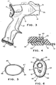
- the cover 11 consists of a left half 12 which encloses the left side of the frame 19 and a right half 13 which encloses the right side of the frame 19. Details of the left half 12 are shown in Fig. 1 and details of the right half are shown in Fig. 3.
- a tab 34 projects from the front end 15 of the half 12 and a tab 35 projects from the front end 15 of the half 13.
- a groove 36 is formed in the housing half 12 and a groove 37 is formed in the housing half 13.
- the grooves 36 and 37 each extend partially around the rear end 16. At the top 29 of the gun 10, the grooves 36 and 37 in the two halves 12 and 13 align when the halves 12 and 13 are abutting to form a single groove 38 which extends more than 180° around the rear end 16 of the cover 11.
- a groove 39 is formed in the housing half 12 and a corresponding groove 40 is formed in the housing half 13 adjacent the handle end 18. When the handle halves 12 and 13 are abutting, the grooves 39 and 40 connect to form a single groove extending completely around the handle 17 adjacent the end 18.
- a pair of raised ribs 41 may be provided on the cover half 12 on opposite sides of the groove 39 and a pair of raised ribs 42 may be provided on the cover half 13 on opposite sides of the groove 40.
- the tabs 34 and 35 are inserted into notches 43 on opposite sides of the front end 23 of the frame body 20. As shown in Fig. 4, one side of the notches 43 may be closed by the retainer ring 22. By hooking the tabs 34 and 35 into the notches 43, the front end 15 of the cover halves 12 and 13 are secured to the frame 19. The cover halves 12 and 13 are held together and an upper spring clip 44 is expanded and inserted into the groove 38, as shown in Figs. 1 and 2. The upper spring clip 44 holds the rear ends 16 of the cover halves 12 and 13 together.
- a lower spring clip 45 also is expanded and placed in the aligned cover grooves 39 and 40 to hold the lower ends 18 of the cover handle portion 17 together, as shown in Figs. 1, 2 and 6.
- the ribs 42 and 43 help retain the lower spring clip 45 in the grooves 39 and 40.
- the tabs 34 and 35 and the two spring clips 44 and 45 eliminate the need for screws to secure the cover halves 12 and 13 together over the gun frame 19, while facilitating removal of the cover halves 12 and 13 for cleaning or replacement. The elimination of screws is particularly useful on tools that have multiple underlying mechanisms which require clearance for their actions.
- the clip 45 is formed from spring wire which is shaped into a loop 46 which terminates at overlapping looped ends 47 and 48.
- the loop 46 has the general shape of, but normally is smaller than, the aligned grooves 39 and 40. By separating the ends 47 and 48, the loop 46 may be expanded sufficiently to permit placement of the loop 46 in the aligned grooves 39 and 40. When the ends 47 and 48 are released, the resilient clip 45 contracts to hold the cover halves together.
- the clip 44 is formed from spring wire into a generally C-shaped body 49 which terminates at opposite free ends 50 and 51.
- the body 49 has the general shape of, but is normally smaller than, the groove 38.
- a U-shaped bend 52 may be formed in the centre of the body 49 to facilitate separating the ends 50 and 51 for placement of the clip in the groove 38.
- the clip 44 holds the adjacent portion of the cover halves 12 and 13 together.
- a tab 55 projects forward from the gun handle 17 immediately below the path of movement of the trigger 27.
- the tab 55 positions the lower fingers on the handle 17 so that they do not interfere with trigger movement.
- One technique is to mould the edges of the cover halves 12 and 13 slightly convex so that they will be slightly deflected or under stress in the region of the tab 55 when the cover halves are clamped together by the spring clips 44 and 45.
- Figs. 9 to 11 illustrate a second technique to assure that the cover halves 12 and 13 are held tightly together in the centre of the handle 17 and especially adjacent the tab 55.
- the cover halves 12 and 13 are hollow for receiving the gun frame 19.
- a hook 56 is moulded on the cover half 12 to project into the cover half 13 and engage a groove 57.
- the halves 12 and 13 are locked together at the tab 55.
- Fig. 12 illustrates a further embodiment wherein the cover halves 12 and 13 are secured together adjacent the tab 55 by a screw 58 which is recessed in a stepped hole 59 in the cover half 12 and in a stepped hole 60 in the cover half 13.
- the removable cover was described for and is particularly useful for a paint spray gun, it will be apparent to those skilled in the art that the cover also is adaptable to other gun shaped tools such as pneumatic nailers and staplers.
- the removable cover may be formed from a relatively soft plastic material which will not mar walls and wood trim as the stapler is used to install carpet.
Landscapes
- Engineering & Computer Science (AREA)
- Mechanical Engineering (AREA)
- Nozzles (AREA)
- Details Or Accessories Of Spraying Plant Or Apparatus (AREA)
- Portable Nailing Machines And Staplers (AREA)
- Catching Or Destruction (AREA)
- Clamps And Clips (AREA)
- Application Of Or Painting With Fluid Materials (AREA)
Claims (8)
- Abnehmbares Gehäuse (10) für ein pistolenförmiges Werkzeug, das einen Körper (20) und einen Griff (21) aufweist, der sich von dem Körper (20) aus erstreckt, wobei das Gehäuse (10) eine erste und eine zweite Gehäusehälfte (12, 13) aufweist, wobei die Gehäusehälften (12, 13) eine Form und Größe haben, daß sie wenigstens einen Bereich des Werkzeugkörpers (20) und des Griffes (21) umschließen, wenn die Hälften (12, 13) aneinander positioniert sind,
dadurch gekennzeichnet,daß jede der Gehäusehälften (12, 13) eine Lappenanordnung (34) hat, die von einem vorderen Endbereich vorspringt, um mit einem Ausschnitt an dem Werkzeug in Eingriff zu gelangen, um die vorderen Endbereiche des Gehäuses (10) an dem Werkzeug zu befestigen, wobei jede der Gehäusehälften (12, 13) eine erste Nut (37) angrenzend an einen hinteren Bereich und eine zweite Nut (40) angrenzend an ein Ende des Griffbereichs hat,daß eine erste Federclipeinrichtung (44) zur Positionierung in den genannten ersten Nuten (37) vorgesehen und dazu ausgebildet ist, die hinteren Gehäusebereiche aneinander zu befestigen,und daß eine zweite Federclipeinrichtung (45) zur Positionierung in den zweiten Nuten (40) vorgesehen und dazu ausgebildet ist, die Gehäusegriffbereiche aneinander zu befestigen. - Abnehmbares Gehäuse nach Anspruch 1,wobei jede der ersten Nuten (37) ein Ende hat, das mit einem Ende der anderen ersten Nut (37) fluchtet, wenn die Gehäusehälften (12, 13) aneinander positioniert sind,und wobei jede der zweiten Nuten (40) ein Ende hat, das mit einem Ende der anderen zweiten Nut (40) fluchtet, wenn die Gehäusehälften (12, 13) aneinander positioniert sind.
- Abnehmbares Gehäuse nach Anspruch 1 oder 2,wobei jede zweite Nut (40) zwei Enden hat, die mit den Enden der anderen zweiten Nut (40) fluchten, wenn die Gehäusehälften (12, 13) aneinander positioniert sind, so daß sich die zweiten Nuten vollständig um die Griffendbereiche herum erstrecken.
- Abnehmbares Gehäuse nach einem der vorhergehenden Ansprüche,wobei jede Gehäusehälfte (12, 13) ein Paar von Rippen (41, 42) hat, die an dem Griffendbereich für die jeweilige Gehäusehälfte ausgebildet sind,und wobei sich die zweite Nut (40) an jeder Gehäusehälfte zwischen den Rippen an der jeweiligen Gehäusehälfte erstreckt, so daß die Rippen (41, 42) dazu beitragen, die zweite Clipeinrichtung (45) in den zweiten Nuten (40) festzuhalten.
- Abnehmbares Gehäuse nach einem der vorhergehenden Ansprüche,wobei die erste Clipeinrichtung (44) aus Federdraht besteht und im wesentlichen die Form von wenigstens einem Bereich der ersten Nuten (37) hat, wenn die Gehäusehälften (12, 13) aneinander positioniert sind, wobei die erste Clipeinrichtung (44) eine Größe hat, die zum Einsetzen in die ersten Nuten (37) ein Auslenken erforderlich macht,und wobei die zweite Clipeinrichtung (45) aus Federdraht besteht und im wesentlichen die Form von wenigstens einem Bereich der zweiten Nuten (40) hat, wenn die Gehäusehälften (12, 13) aneinander positioniert sind, wobei die zweite Clipeinrichtung (45) eine Größe hat, die zum Einsetzen in die zweiten Nuten (40) ein Auslenken erforderlich macht.
- Abnehmbares Gehäuse nach einem der vorhergehenden Ansprüche,zur Verwendung bei einer Spritzpistole, die einen Rahmen hat, der einen Körper (20) und einen Griff (21) mit einem freien Ende aufweist.
- Farbspritzpistole, die folgendes aufweist:einen Rahmen, der einen Körper (20) und einen Griff (21) mit einem freien Ende bildet, und ein abnehmbares Gehäuse nach Anspruch 6, das mit seiner ersten und seiner zweiten Gehäusehälfte (12, 13) so angeordnet ist, daß es wenigstens einen Bereich des Rahmenkörpers (20) und des Griffs (21) umschließt,wobei jede der Gehäusehälften (12, 13) einen Lappen (34) hat, der von einem vorderen Endbereich vorspringt und mit einem Ausschnitt an der Pistole (20) in Eingriff gelangt, um den vorderen Endbereich der jeweiligen Gehäusehälfte an der Pistole zu befestigen,wobei der erste Halte-Federclip (44) in den ersten Nuten (37) positioniert ist und der erste Clip (44) die ersten Endbereiche der Gehäusehälften (12, 13) zusammenhält, und wobei der zweite Halte-Federclip (45) in den zweiten Nuten (40) positioniert ist und die Griffendbereiche zusammenhält.
- Farbspritzpistole nach Anspruch 7,die ferner einen Fluidkopf-Haltering (22) aufweist, der an einem Vorderende des Pistolenkörpers (20) befestigt ist,und wobei sich die Ausschnitte zur Aufnahme der Gehäusehälftenlappen (34) zwischen dem Vorderende des Körpers (20) und dem Haltering (22) befinden.
Applications Claiming Priority (2)
| Application Number | Priority Date | Filing Date | Title |
|---|---|---|---|
| US142825 | 1993-10-25 | ||
| US08/142,825 US5332156A (en) | 1993-10-25 | 1993-10-25 | Spray gun with removable cover and method for securing a cover to a spray gun |
Publications (2)
| Publication Number | Publication Date |
|---|---|
| EP0653272A1 EP0653272A1 (de) | 1995-05-17 |
| EP0653272B1 true EP0653272B1 (de) | 1999-12-22 |
Family
ID=22501444
Family Applications (1)
| Application Number | Title | Priority Date | Filing Date |
|---|---|---|---|
| EP94307750A Expired - Lifetime EP0653272B1 (de) | 1993-10-25 | 1994-10-21 | Abnehmbarer Schutz für ein Pistolenförmiges Werkzeug |
Country Status (7)
| Country | Link |
|---|---|
| US (1) | US5332156A (de) |
| EP (1) | EP0653272B1 (de) |
| AT (1) | ATE187916T1 (de) |
| CA (1) | CA2132040C (de) |
| DE (1) | DE69422267T2 (de) |
| FI (1) | FI945011A7 (de) |
| NO (1) | NO944049L (de) |
Families Citing this family (95)
| Publication number | Priority date | Publication date | Assignee | Title |
|---|---|---|---|---|
| GB9410697D0 (en) * | 1994-05-27 | 1994-07-13 | Avdel Systems Ltd | Adaptor for hand-held power tool |
| US5836517A (en) * | 1995-01-03 | 1998-11-17 | Ransburg Corporation | Spray gun with fluid valve |
| DE19608360A1 (de) * | 1996-03-01 | 1997-09-04 | Fein C & E | Motorbetriebenes Handwerkzeug |
| US5803313A (en) * | 1996-05-21 | 1998-09-08 | Illinois Tool Works Inc. | Hand held fluid dispensing apparatus |
| US5823237A (en) * | 1996-06-24 | 1998-10-20 | Alvern-Norway A/S | Protective cover for a fuel pump filler gun and method for protecting same |
| US5860462A (en) * | 1996-06-24 | 1999-01-19 | Alvern-Norway | Protective cover for a fuel pump filler gun and method for protecting same |
| US5904191A (en) * | 1996-06-24 | 1999-05-18 | Alvern-Norway A/S | Protective cover for a fuel pump filler gun |
| US5921283A (en) * | 1996-06-24 | 1999-07-13 | Alvern-Norway A/S | Protective cover for a fuel pump filler gun and method for protecting same |
| USD387849S (en) * | 1996-10-24 | 1997-12-16 | Yuan Mei Corporation | Handle of a spray gun |
| US5862989A (en) * | 1997-06-25 | 1999-01-26 | Cirillo; Jeffery C. | Spray gun cover |
| SE509548C2 (sv) * | 1997-06-25 | 1999-02-08 | Electrolux Ab | Anordning vid handmanövrerad bearbetningsmaskin |
| US6082468A (en) * | 1998-04-20 | 2000-07-04 | Snap-On Tools Company | Interchangeable grips for power hand tools |
| USD459432S1 (en) | 1999-05-14 | 2002-06-25 | Sata-Farbspritztechnik Gmbh & Co. | Spray gun head ring |
| US20020117531A1 (en) * | 2001-02-07 | 2002-08-29 | Schell Craig A. | Fastener tool |
| US6547015B1 (en) | 2001-03-29 | 2003-04-15 | Snap-On Technologies, Inc. | Elongated pneumatic tool with replaceable soft grip |
| US6854667B2 (en) * | 2001-09-06 | 2005-02-15 | Graco Minnesota Inc. | Spray gun having indexing air cap with quick release retaining ring |
| US20030042333A1 (en) * | 2001-09-06 | 2003-03-06 | Wiersma Roger E. | Spray gun having multiple size handles |
| USD459260S1 (en) | 2001-09-21 | 2002-06-25 | Douglas Conlin | Shield for a robot arm in a paint spray booth |
| US6612476B2 (en) | 2002-01-14 | 2003-09-02 | Illinois Tool Works Inc. | Fastener driving tool with modular construction |
| US6796389B2 (en) * | 2002-03-28 | 2004-09-28 | Snap-On Incorporated | Power hand tool and removable grip therefor |
| US6722549B2 (en) * | 2002-05-08 | 2004-04-20 | Yury Shkolnikov | Arm member for fastener driving tool |
| US6536688B1 (en) * | 2002-05-24 | 2003-03-25 | Success & Tech Industrial Co., Ltd. | Two-piece hand grip structure of pistol nozzle with flow regulating control knob |
| US6669114B1 (en) | 2002-07-10 | 2003-12-30 | Campbell Hausfeld/Scott Fetzer Company | Actuator and handle for a paint sprayer |
| US7066406B2 (en) * | 2002-07-10 | 2006-06-27 | Campbell Hausfeld/Scott Fetzer Company | Paint sprayer |
| US6964382B2 (en) * | 2002-08-30 | 2005-11-15 | Illinois Tool Works Inc. | Grip cover for coating dispensing device hand grip |
| US8322040B2 (en) * | 2003-05-23 | 2012-12-04 | Exceptional Ip Holdings Llc | Handle including two handgrips and/or a hand alignment mechanism |
| USD494656S1 (en) | 2003-07-02 | 2004-08-17 | Orbit Irrigation Products, Inc. | Handle for hand-held sprinkler |
| DE10344164A1 (de) * | 2003-09-22 | 2005-04-28 | Rexroth Indramat Gmbh | Winkelartige Handarbeitsmaschine |
| US20040139835A1 (en) * | 2003-12-22 | 2004-07-22 | Stuart Wright | Band saw with bumpers |
| US7296760B2 (en) * | 2004-11-17 | 2007-11-20 | Illinois Tool Works Inc. | Indexing valve |
| US7296759B2 (en) | 2004-11-19 | 2007-11-20 | Illinois Tool Works Inc. | Ratcheting retaining ring |
| US20060202060A1 (en) * | 2004-12-06 | 2006-09-14 | Alexander Kevin L | Dispensing device handle assembly |
| US7757973B2 (en) * | 2005-04-04 | 2010-07-20 | Illinois Tool Works Inc. | Hand-held coating dispensing device |
| US7677476B2 (en) * | 2005-05-02 | 2010-03-16 | Campbell Hausfeld/Scott Fetzer Company | Extension pole apparatus |
| US7460924B2 (en) * | 2005-06-16 | 2008-12-02 | Illinois Tool Works Inc. | In-gun power supply control |
| US7364098B2 (en) * | 2005-10-12 | 2008-04-29 | Illinois Tool Works Inc. | Material dispensing apparatus |
| US7222767B1 (en) * | 2005-12-19 | 2007-05-29 | Besco Pneumatic Corp. | Nail gun with an adjustable clip assembly |
| USD545943S1 (en) | 2006-03-14 | 2007-07-03 | Illinois Tool Works Inc. | Coating material dispensing device |
| US7455249B2 (en) | 2006-03-28 | 2008-11-25 | Illinois Tool Works Inc. | Combined direct and indirect charging system for electrostatically-aided coating system |
| US20110253810A1 (en) * | 2006-08-03 | 2011-10-20 | Johannes Oskar Rieger | Pistol for integrated administering a liquid and a compressing air flow |
| DE102006041429A1 (de) * | 2006-09-04 | 2008-03-20 | Metabowerke Gmbh | Elektrohandwerkzeuggerät |
| DE502007000825D1 (de) | 2006-12-05 | 2009-07-16 | Sata Gmbh & Co Kg | Belüftung für den Fließbecher einer Farbspritzpistole |
| US8496194B2 (en) | 2008-03-10 | 2013-07-30 | Finishing Brands Holdings Inc. | Method and apparatus for retaining highly torqued fittings in molded resin or polymer housing |
| US7926748B2 (en) | 2008-03-10 | 2011-04-19 | Illinois Tool Works Inc. | Generator for air-powered electrostatically aided coating dispensing device |
| US8770496B2 (en) | 2008-03-10 | 2014-07-08 | Finishing Brands Holdings Inc. | Circuit for displaying the relative voltage at the output electrode of an electrostatically aided coating material atomizer |
| USD608858S1 (en) | 2008-03-10 | 2010-01-26 | Illinois Tool Works Inc. | Coating material dispensing device |
| US8016213B2 (en) | 2008-03-10 | 2011-09-13 | Illinois Tool Works Inc. | Controlling temperature in air-powered electrostatically aided coating material atomizer |
| US7988075B2 (en) | 2008-03-10 | 2011-08-02 | Illinois Tool Works Inc. | Circuit board configuration for air-powered electrostatically aided coating material atomizer |
| US8590817B2 (en) | 2008-03-10 | 2013-11-26 | Illinois Tool Works Inc. | Sealed electrical source for air-powered electrostatic atomizing and dispensing device |
| EP2265387B1 (de) | 2008-03-12 | 2015-05-06 | Jeffrey D. Fox | Wegwerf-spritzpistolenkartusche |
| US7918409B2 (en) * | 2008-04-09 | 2011-04-05 | Illinois Tool Works Inc. | Multiple charging electrode |
| FR2935106B1 (fr) * | 2008-08-22 | 2010-09-17 | Pellenc Sa | Outil electroportatif a commande par gachette |
| DE202008014389U1 (de) * | 2008-10-29 | 2010-04-08 | Sata Gmbh & Co. Kg | Fließbecher für eine Farbspritzpistole |
| WO2010085801A2 (en) * | 2009-01-26 | 2010-07-29 | 3M Innovative Properties Company | Liquid spray gun, spray gun platform, and spray head assembly |
| US8225968B2 (en) * | 2009-05-12 | 2012-07-24 | Illinois Tool Works Inc. | Seal system for gear pumps |
| DE102009032399A1 (de) | 2009-07-08 | 2011-01-13 | Sata Gmbh & Co. Kg | Farbspritzpistole |
| EP2364818B1 (de) * | 2010-03-08 | 2017-08-16 | HILTI Aktiengesellschaft | Handwerkzeugmaschine |
| DE202010007355U1 (de) | 2010-05-28 | 2011-10-20 | Sata Gmbh & Co. Kg | Düsenkopf für eine Spritzvorrichtung |
| CA2816329A1 (en) * | 2010-10-26 | 2012-05-03 | Thomas W. Honsa | Tool |
| US9333519B2 (en) | 2010-12-02 | 2016-05-10 | Sata Gmbh & Co. Kg | Spray gun and accessories |
| EP3476492B1 (de) | 2011-02-09 | 2020-05-27 | 3M Innovative Properties Co. | Düsenspitzen und sprühkopfanordnungen für flüssigkeitsspritzpistolen |
| CN107537707B (zh) | 2011-06-30 | 2021-09-03 | 萨塔有限两合公司 | 喷枪、喷射介质引导单元、盖子、底座本体及相关方法 |
| CA2843266C (en) | 2011-07-28 | 2020-06-16 | 3M Innovative Properties Company | Spray head assembly with integrated air cap/nozzle for a liquid spray gun |
| EP2766126B1 (de) | 2011-10-12 | 2019-11-27 | 3M Innovative Properties Company | Sprühkopfanordnungen für flüssigkeitsspritzpistolen |
| MX370998B (es) | 2012-03-06 | 2020-01-13 | 3M Innovative Properties Co | Pistola pulverizadora que tiene pasaje de sobrecompresion interno. |
| CA2867805A1 (en) | 2012-03-23 | 2013-09-26 | 3M Innovative Properties Company | Spray gun barrel with inseparable nozzle |
| EP3189940B1 (de) * | 2012-12-25 | 2018-01-31 | Makita Corporation | Schlagwerkzeug |
| RU2638399C2 (ru) | 2013-07-15 | 2017-12-13 | 3М Инновейтив Пропертиз Компани | Пневмоколпачки с фигурными вставками для жидкостных пистолетов-распылителей |
| CA155474S (en) | 2013-09-27 | 2015-08-27 | Sata Gmbh & Co Kg | Spray gun |
| DE202013105779U1 (de) | 2013-12-18 | 2015-03-19 | Sata Gmbh & Co. Kg | Luftdüsenabschluss für eine Lackierpistole |
| JP6246649B2 (ja) * | 2014-04-10 | 2017-12-13 | 株式会社マキタ | 電動工具 |
| USD758537S1 (en) | 2014-07-31 | 2016-06-07 | Sata Gmbh & Co. Kg | Paint spray gun rear portion |
| CA159961S (en) | 2014-07-31 | 2015-07-17 | Sata Gmbh & Co Kg | Spray gun |
| CN105289870B (zh) | 2014-07-31 | 2019-09-24 | 萨塔有限两合公司 | 喷枪的制造方法、喷枪、喷枪本体以及盖 |
| USD768820S1 (en) | 2014-09-03 | 2016-10-11 | Sata Gmbh & Co. Kg | Paint spray gun with pattern |
| US9539718B2 (en) * | 2014-12-19 | 2017-01-10 | Jeffery Hall | Ergonomic handle for a fluid applicator spray gun |
| DE102015006484A1 (de) | 2015-05-22 | 2016-11-24 | Sata Gmbh & Co. Kg | Düsenanordnung für eine Spritzpistole, insbesondere Farbspritzpistole und Spritzpistole, insbesondere Farbspritzpistole |
| DE102015016474A1 (de) | 2015-12-21 | 2017-06-22 | Sata Gmbh & Co. Kg | Luftkappe und Düsenanordnung für eine Spritzpistole und Spritzpistole |
| CN205995666U (zh) | 2016-08-19 | 2017-03-08 | 萨塔有限两合公司 | 喷枪及其扳机 |
| CN205966208U (zh) | 2016-08-19 | 2017-02-22 | 萨塔有限两合公司 | 风帽组件以及喷枪 |
| US11007545B2 (en) | 2017-01-15 | 2021-05-18 | Graco Minnesota Inc. | Handheld airless paint sprayer repair |
| CA3012157A1 (en) * | 2018-07-24 | 2020-01-24 | SprayTech Innovations | Spray foam gun cover |
| DE102018118738A1 (de) | 2018-08-01 | 2020-02-06 | Sata Gmbh & Co. Kg | Grundkörper für eine Spritzpistole, Spritzpistolen, Spritzpistolen-Set, Verfahren zur Herstellung eines Grundkörpers für eine Spritzpistole und Verfahren zum Umrüsten einer Spritzpistole |
| USD907744S1 (en) * | 2018-08-01 | 2021-01-12 | Lutz Pumpen Gmbh | Dispenser nozzle |
| DE102018118737A1 (de) | 2018-08-01 | 2020-02-06 | Sata Gmbh & Co. Kg | Düse für eine Spritzpistole, Düsensatz für eine Spritzpistole, Spritzpistolen und Verfahren zur Herstellung einer Düse für eine Spritzpistole |
| CN112533705B (zh) | 2018-08-01 | 2023-07-04 | 萨塔有限两合公司 | 喷枪的喷嘴组、喷枪系统、制造喷嘴模块的方法、为上漆任务从喷嘴组选出喷嘴模块的方法、选择系统和计算机程序产品 |
| USD905821S1 (en) * | 2018-09-10 | 2020-12-22 | ROMER Sp.Cywilna Andrzej Ciura, Wojciech Ciura | Spray gun |
| DE102018122004A1 (de) | 2018-09-10 | 2020-03-12 | Sata Gmbh & Co. Kg | Lackierpistole, Materialauftragssystem und Verfahren zu dessen Betrieb |
| US12060656B2 (en) * | 2018-11-11 | 2024-08-13 | E-Spin Nanotech Private Limited | Capillary type multi-jet nozzle for fabricating high throughput nanofibers |
| USD891578S1 (en) * | 2019-04-05 | 2020-07-28 | Graco Minnesota Inc. | Electrostatic spray gun air cap |
| DE102020106172A1 (de) | 2020-03-06 | 2021-09-09 | Sata Gmbh & Co. Kg | Spritzpistole, insbesondere druckluftzerstäubende Farbspritzpistole, insbesondere handgeführte druckluftzerstäubende Farbspritzpistole |
| DE102020123769A1 (de) | 2020-09-11 | 2022-03-17 | Sata Gmbh & Co. Kg | Dichtelement zum Abdichten eines Übergangs zwischen einem Grundkörper einer Spritzpistole und einem Anbauteil einer Spritzpistole, Anbauteil, insbesondere Farbdüsenanordnung, für eine Spritzpistole und Spritzpistole, insbesondere Farbspritzpistole |
| USD1046076S1 (en) | 2021-10-15 | 2024-10-08 | Sata Gmbh & Co. Kg | Spray gun |
| US20250172137A1 (en) * | 2022-02-28 | 2025-05-29 | Graco Minnesota Inc. | Pump motor handle |
| USD1017767S1 (en) * | 2022-04-18 | 2024-03-12 | Xiaogang Zhang | Spray gun |
Citations (1)
| Publication number | Priority date | Publication date | Assignee | Title |
|---|---|---|---|---|
| US3006560A (en) * | 1958-11-14 | 1961-10-31 | Lafayette Brass Mfg Co Inc | Spray gun |
Family Cites Families (15)
| Publication number | Priority date | Publication date | Assignee | Title |
|---|---|---|---|---|
| US2629908A (en) * | 1950-12-11 | 1953-03-03 | Cecil W Keck | Hose clamp |
| US3159047A (en) * | 1962-09-21 | 1964-12-01 | George F Dable | Segmented gear |
| US3846033A (en) * | 1969-12-31 | 1974-11-05 | Bethlehem Steel Corp | Vibration damped fitting |
| US3799447A (en) * | 1973-04-19 | 1974-03-26 | Smith R Inc | Hose nozzle with improved insulating protector structure |
| US4294411A (en) * | 1979-07-05 | 1981-10-13 | Nordson Corporation | Electrostatic spray gun |
| US4286734A (en) * | 1979-07-17 | 1981-09-01 | Tonge Donald R | Liquid mix dispensing gun |
| DE3002790C2 (de) * | 1980-01-26 | 1982-07-29 | Josef 7918 Illertissen Kränzle | Halte- und Betätigungsvorrichtung für Spritzeinrichtungen von Hochdruckwaschanlagen |
| DE3300290A1 (de) * | 1982-10-06 | 1984-07-12 | Wolfgang 4800 Bielefeld Suttner | Spritzvorrichtung |
| US4700876A (en) * | 1985-11-01 | 1987-10-20 | Arrow Fastener Company, Inc. | Staple driving tool |
| US4706598A (en) * | 1986-05-01 | 1987-11-17 | Jeffress William L | Detachable handle extender and transverse enlarger for use with longitudinally reciprocable handles or plungers by handicapped persons |
| US4776517A (en) * | 1986-06-23 | 1988-10-11 | L. R. Nelson Corporation | Pistol grip hose nozzle |
| US4915303A (en) * | 1987-09-28 | 1990-04-10 | Accuspray, Inc. | Paint spray gun |
| DE4007880A1 (de) * | 1990-02-28 | 1991-08-29 | Suttner Gmbh & Co Kg | Ventilpistole fuer ein hochdruckreinigungsgeraet o. dgl. |
| JP2501222Y2 (ja) * | 1990-05-09 | 1996-06-12 | 株式会社共立 | 合成樹脂製グリップ |
| US5143299A (en) * | 1991-03-26 | 1992-09-01 | Melnor Industries, Inc. | Spray gun |
-
1993
- 1993-10-25 US US08/142,825 patent/US5332156A/en not_active Expired - Lifetime
-
1994
- 1994-09-14 CA CA002132040A patent/CA2132040C/en not_active Expired - Fee Related
- 1994-10-21 AT AT94307750T patent/ATE187916T1/de not_active IP Right Cessation
- 1994-10-21 EP EP94307750A patent/EP0653272B1/de not_active Expired - Lifetime
- 1994-10-21 DE DE69422267T patent/DE69422267T2/de not_active Expired - Fee Related
- 1994-10-24 NO NO944049A patent/NO944049L/no unknown
- 1994-10-25 FI FI945011A patent/FI945011A7/fi not_active Application Discontinuation
Patent Citations (1)
| Publication number | Priority date | Publication date | Assignee | Title |
|---|---|---|---|---|
| US3006560A (en) * | 1958-11-14 | 1961-10-31 | Lafayette Brass Mfg Co Inc | Spray gun |
Also Published As
| Publication number | Publication date |
|---|---|
| FI945011A0 (fi) | 1994-10-25 |
| DE69422267T2 (de) | 2000-05-11 |
| CA2132040C (en) | 1999-12-28 |
| EP0653272A1 (de) | 1995-05-17 |
| ATE187916T1 (de) | 2000-01-15 |
| US5332156A (en) | 1994-07-26 |
| NO944049D0 (no) | 1994-10-24 |
| DE69422267D1 (de) | 2000-01-27 |
| FI945011A7 (fi) | 1995-04-26 |
| CA2132040A1 (en) | 1995-04-26 |
| NO944049L (no) | 1995-04-26 |
Similar Documents
| Publication | Publication Date | Title |
|---|---|---|
| US5332156A (en) | Spray gun with removable cover and method for securing a cover to a spray gun | |
| US6679414B2 (en) | Interchangeable magazine for a tool | |
| US6913180B2 (en) | Nail gun | |
| US4319705A (en) | Fastener driving tool | |
| KR920009969B1 (ko) | 고정구를 박는 공압식공구 | |
| EP0644020B1 (de) | Eintreibgerät für Befestigungselemente | |
| WO2020086980A1 (en) | Mix chamber for a plural component sprayer | |
| US20050001007A1 (en) | Pneumatic nailer | |
| JP2002337068A (ja) | 打込工具 | |
| US20140027488A1 (en) | Adjustable Exhaust Assembly For Pneumatic Fasteners | |
| US7857242B2 (en) | Quick connection device for electric spray gun | |
| GB2024692A (en) | Fastener driver tool | |
| GB2240061A (en) | Power actuated device for installing metal corner strip | |
| US4294391A (en) | Fastener driving tool | |
| JPS60213486A (ja) | フアスナ打込み工具 | |
| US4671443A (en) | Replaceable magazine system for a fastener driving tool | |
| US5040400A (en) | Power actuated tool for installing metal corner strip | |
| WO2003082529A1 (en) | Power hand tool and removable grip therefor | |
| US5551157A (en) | Tool handle assembly for garden tools | |
| US6543705B1 (en) | Mold spray gun structure | |
| CN111113336A (zh) | 紧固件驱动器及操作紧固件驱动器的方法 | |
| US11679480B2 (en) | Nosepiece latch mechanism for a fastening tool | |
| US7080576B2 (en) | Multi-accessory hammer with rapid release change mechanism | |
| US6939089B1 (en) | Surform file holder with tensioning adjustment | |
| KR200442386Y1 (ko) | 개량형 메가진 커버 이탈방지수단이 구비된 타카장치 |
Legal Events
| Date | Code | Title | Description |
|---|---|---|---|
| PUAI | Public reference made under article 153(3) epc to a published international application that has entered the european phase |
Free format text: ORIGINAL CODE: 0009012 |
|
| AK | Designated contracting states |
Kind code of ref document: A1 Designated state(s): AT BE CH DE DK ES FR GB GR IE IT LI LU NL PT SE |
|
| 17P | Request for examination filed |
Effective date: 19951027 |
|
| 17Q | First examination report despatched |
Effective date: 19980122 |
|
| GRAG | Despatch of communication of intention to grant |
Free format text: ORIGINAL CODE: EPIDOS AGRA |
|
| GRAG | Despatch of communication of intention to grant |
Free format text: ORIGINAL CODE: EPIDOS AGRA |
|
| GRAH | Despatch of communication of intention to grant a patent |
Free format text: ORIGINAL CODE: EPIDOS IGRA |
|
| GRAH | Despatch of communication of intention to grant a patent |
Free format text: ORIGINAL CODE: EPIDOS IGRA |
|
| GRAA | (expected) grant |
Free format text: ORIGINAL CODE: 0009210 |
|
| AK | Designated contracting states |
Kind code of ref document: B1 Designated state(s): AT BE CH DE DK ES FR GB GR IE IT LI LU NL PT SE |
|
| PG25 | Lapsed in a contracting state [announced via postgrant information from national office to epo] |
Ref country code: SE Free format text: THE PATENT HAS BEEN ANNULLED BY A DECISION OF A NATIONAL AUTHORITY Effective date: 19991222 Ref country code: NL Free format text: LAPSE BECAUSE OF FAILURE TO SUBMIT A TRANSLATION OF THE DESCRIPTION OR TO PAY THE FEE WITHIN THE PRESCRIBED TIME-LIMIT Effective date: 19991222 Ref country code: LI Free format text: LAPSE BECAUSE OF FAILURE TO SUBMIT A TRANSLATION OF THE DESCRIPTION OR TO PAY THE FEE WITHIN THE PRESCRIBED TIME-LIMIT Effective date: 19991222 Ref country code: GR Free format text: LAPSE BECAUSE OF NON-PAYMENT OF DUE FEES Effective date: 19991222 Ref country code: ES Free format text: THE PATENT HAS BEEN ANNULLED BY A DECISION OF A NATIONAL AUTHORITY Effective date: 19991222 Ref country code: CH Free format text: LAPSE BECAUSE OF FAILURE TO SUBMIT A TRANSLATION OF THE DESCRIPTION OR TO PAY THE FEE WITHIN THE PRESCRIBED TIME-LIMIT Effective date: 19991222 Ref country code: BE Free format text: LAPSE BECAUSE OF FAILURE TO SUBMIT A TRANSLATION OF THE DESCRIPTION OR TO PAY THE FEE WITHIN THE PRESCRIBED TIME-LIMIT Effective date: 19991222 Ref country code: AT Free format text: LAPSE BECAUSE OF FAILURE TO SUBMIT A TRANSLATION OF THE DESCRIPTION OR TO PAY THE FEE WITHIN THE PRESCRIBED TIME-LIMIT Effective date: 19991222 |
|
| REF | Corresponds to: |
Ref document number: 187916 Country of ref document: AT Date of ref document: 20000115 Kind code of ref document: T |
|
| REG | Reference to a national code |
Ref country code: CH Ref legal event code: EP |
|
| REF | Corresponds to: |
Ref document number: 69422267 Country of ref document: DE Date of ref document: 20000127 |
|
| ET | Fr: translation filed | ||
| REG | Reference to a national code |
Ref country code: IE Ref legal event code: FG4D |
|
| ITF | It: translation for a ep patent filed | ||
| PG25 | Lapsed in a contracting state [announced via postgrant information from national office to epo] |
Ref country code: PT Free format text: LAPSE BECAUSE OF FAILURE TO SUBMIT A TRANSLATION OF THE DESCRIPTION OR TO PAY THE FEE WITHIN THE PRESCRIBED TIME-LIMIT Effective date: 20000322 Ref country code: DK Free format text: LAPSE BECAUSE OF FAILURE TO SUBMIT A TRANSLATION OF THE DESCRIPTION OR TO PAY THE FEE WITHIN THE PRESCRIBED TIME-LIMIT Effective date: 20000322 |
|
| NLV1 | Nl: lapsed or annulled due to failure to fulfill the requirements of art. 29p and 29m of the patents act | ||
| REG | Reference to a national code |
Ref country code: CH Ref legal event code: PL |
|
| PG25 | Lapsed in a contracting state [announced via postgrant information from national office to epo] |
Ref country code: LU Free format text: LAPSE BECAUSE OF NON-PAYMENT OF DUE FEES Effective date: 20001021 |
|
| PLBE | No opposition filed within time limit |
Free format text: ORIGINAL CODE: 0009261 |
|
| STAA | Information on the status of an ep patent application or granted ep patent |
Free format text: STATUS: NO OPPOSITION FILED WITHIN TIME LIMIT |
|
| PG25 | Lapsed in a contracting state [announced via postgrant information from national office to epo] |
Ref country code: IE Free format text: LAPSE BECAUSE OF NON-PAYMENT OF DUE FEES Effective date: 20001023 |
|
| 26N | No opposition filed | ||
| REG | Reference to a national code |
Ref country code: IE Ref legal event code: MM4A |
|
| REG | Reference to a national code |
Ref country code: GB Ref legal event code: IF02 |
|
| PGFP | Annual fee paid to national office [announced via postgrant information from national office to epo] |
Ref country code: FR Payment date: 20021002 Year of fee payment: 9 |
|
| PGFP | Annual fee paid to national office [announced via postgrant information from national office to epo] |
Ref country code: GB Payment date: 20021016 Year of fee payment: 9 |
|
| PGFP | Annual fee paid to national office [announced via postgrant information from national office to epo] |
Ref country code: DE Payment date: 20021031 Year of fee payment: 9 |
|
| PG25 | Lapsed in a contracting state [announced via postgrant information from national office to epo] |
Ref country code: GB Free format text: LAPSE BECAUSE OF NON-PAYMENT OF DUE FEES Effective date: 20031021 |
|
| PG25 | Lapsed in a contracting state [announced via postgrant information from national office to epo] |
Ref country code: DE Free format text: LAPSE BECAUSE OF NON-PAYMENT OF DUE FEES Effective date: 20040501 |
|
| GBPC | Gb: european patent ceased through non-payment of renewal fee |
Effective date: 20031021 |
|
| PG25 | Lapsed in a contracting state [announced via postgrant information from national office to epo] |
Ref country code: FR Free format text: LAPSE BECAUSE OF NON-PAYMENT OF DUE FEES Effective date: 20040630 |
|
| REG | Reference to a national code |
Ref country code: FR Ref legal event code: ST |
|
| PG25 | Lapsed in a contracting state [announced via postgrant information from national office to epo] |
Ref country code: IT Free format text: LAPSE BECAUSE OF NON-PAYMENT OF DUE FEES Effective date: 20051021 |