EP0653327A2 - Unité d'éclairage modulaire - Google Patents
Unité d'éclairage modulaire Download PDFInfo
- Publication number
- EP0653327A2 EP0653327A2 EP94306718A EP94306718A EP0653327A2 EP 0653327 A2 EP0653327 A2 EP 0653327A2 EP 94306718 A EP94306718 A EP 94306718A EP 94306718 A EP94306718 A EP 94306718A EP 0653327 A2 EP0653327 A2 EP 0653327A2
- Authority
- EP
- European Patent Office
- Prior art keywords
- lighting unit
- modular lighting
- unit according
- attaching
- case
- Prior art date
- Legal status (The legal status is an assumption and is not a legal conclusion. Google has not performed a legal analysis and makes no representation as to the accuracy of the status listed.)
- Granted
Links
Images

Classifications
-
- B—PERFORMING OPERATIONS; TRANSPORTING
- B60—VEHICLES IN GENERAL
- B60Q—ARRANGEMENT OF SIGNALLING OR LIGHTING DEVICES, THE MOUNTING OR SUPPORTING THEREOF OR CIRCUITS THEREFOR, FOR VEHICLES IN GENERAL
- B60Q1/00—Arrangement of optical signalling or lighting devices, the mounting or supporting thereof or circuits therefor
- B60Q1/02—Arrangement of optical signalling or lighting devices, the mounting or supporting thereof or circuits therefor the devices being primarily intended to illuminate the way ahead or to illuminate other areas of way or environments
- B60Q1/04—Arrangement of optical signalling or lighting devices, the mounting or supporting thereof or circuits therefor the devices being primarily intended to illuminate the way ahead or to illuminate other areas of way or environments the devices being headlights
- B60Q1/0483—Arrangement of optical signalling or lighting devices, the mounting or supporting thereof or circuits therefor the devices being primarily intended to illuminate the way ahead or to illuminate other areas of way or environments the devices being headlights mounted on a bracket, e.g. details concerning the mouting of the lamps on the vehicle body
-
- B—PERFORMING OPERATIONS; TRANSPORTING
- B60—VEHICLES IN GENERAL
- B60Q—ARRANGEMENT OF SIGNALLING OR LIGHTING DEVICES, THE MOUNTING OR SUPPORTING THEREOF OR CIRCUITS THEREFOR, FOR VEHICLES IN GENERAL
- B60Q1/00—Arrangement of optical signalling or lighting devices, the mounting or supporting thereof or circuits therefor
- B60Q1/26—Arrangement of optical signalling or lighting devices, the mounting or supporting thereof or circuits therefor the devices being primarily intended to indicate the vehicle, or parts thereof, or to give signals, to other traffic
- B60Q1/2607—Arrangement of optical signalling or lighting devices, the mounting or supporting thereof or circuits therefor the devices being primarily intended to indicate the vehicle, or parts thereof, or to give signals, to other traffic comprising at least two indicating lamps
-
- B—PERFORMING OPERATIONS; TRANSPORTING
- B60—VEHICLES IN GENERAL
- B60Q—ARRANGEMENT OF SIGNALLING OR LIGHTING DEVICES, THE MOUNTING OR SUPPORTING THEREOF OR CIRCUITS THEREFOR, FOR VEHICLES IN GENERAL
- B60Q1/00—Arrangement of optical signalling or lighting devices, the mounting or supporting thereof or circuits therefor
- B60Q1/26—Arrangement of optical signalling or lighting devices, the mounting or supporting thereof or circuits therefor the devices being primarily intended to indicate the vehicle, or parts thereof, or to give signals, to other traffic
- B60Q1/2611—Indicating devices mounted on the roof of the vehicle
Definitions
- This invention relates to lighting equipment and, more particularly, to a modular lighting unit that is particularly suitable for use on on- and off-road vehicles to serve as at least one of a headlight, turn signal, tail light, running light, brake light, etc. on the vehicle.
- the light if the light becomes misaligned, it must be removed to allow the mounting stem to be reshaped. The light must then be re-mounted.
- a further problem with the above structure is that it is relatively limited with respect to the number ad arrangement of lights on the bracket. Sufficient spacing must be left between adjacent lights so that the lights do not contact each other as when they flex with the vehicle in operation. At the same time, the lights must all be mounted at the same vertical height, as dictated by the mounting bracket.
- brackets ad mounting structures for the lights are made from metal. Consequently, as these parts rust or corrode, it becomes more difficult, and at times impossible, to disassemble ad adjust the lights.
- the cases for the above types of lights are usually made relatively simple in shape. That is, in most instances, the cases are square or rectangular. As a result, most of these conventional lights are usually unimaginative in terms of their appearance.
- the present invention is specifically directed to overcoming the above-enumerated problems in a novel and simple manner.
- a modular lighting unit is provided with a case having a front and back and a peripheral wall extending around a light chamber.
- a lens is mounted to the case.
- a reflector in the light chamber directs light from a source forwardly through the lens.
- the peripheral wall is defined at least partially by an exposed surface having a first portion that is other than a flat surface extending either fully horizontally or fully vertically. Structure is provided on the exposed surface portion for attaching another modular lighting unit to the case.
- the exposed surface is flat.
- the attaching structure can take a number of different forms.
- the attaching structure includes a plurality of ribs and recesses.
- the lighting units can be permanently or removably attached.
- the invention also contemplates the combination of the above structure with a mounting base to which the case can be connected.
- the invention further contemplates the combination of the above structure with a guide rail to be attached to a support.
- the mounting base cooperates with the guide rail to allow the mounting base to be maintained in a plurality of different positions relative to the guide rail.
- the support is one of an on- and off-road vehicle.
- the lighting unit can function as one of a headlight, a turn signal, a tail light, a running lights, a brake light, etc. on the vehicle.
- levelling structure can be provided for adjusting the attitude of the mounting base relative to a support for the mounting base.
- the invention contemplates the combination of a first modular lighting unit with a second modular lighting unit, with the first and second modular lighting units being substantially the same.
- the second lighting unit has a second surface portion that can be attached to the first surface portion on the first unit.
- the first and second surface portions are each flat and angled so that with the first and second surface portions abutted to each other, the first and second lighting units have the same orientation.
- peripheral wall surface of the lighting units can take a number of different shapes, in one desirable form, the peripheral wall surface has a diamond shape.
- a third modular lighting unit similar to the first and second lighting units, can be provided.
- the first lighting unit can be constructed to be attached to the third lighting unit.
- only two of the three modular lighting units are connected to a support therefor, with the other module being supported by the support-engaging modules.
- the third module can be supported in cantilever fashion from one or both of the other two modules.
- a fourth lighting unit can be provided for connection to each of the second and third modular lighting units.
- the individual modules can be stacked and interlocked to provide a highly stable system with an infinite number of different overall shapes and designs being possible.
- a light source can be provided as part of the modular lighting unit.
- a modular lighting unit having a case and a light source mounted to the case.
- the case has a peripheral wall defined at least partially by an exposed surface having a first portion that is other than a flat surface extending fully horizontally or fully vertically, with structure on the exposed surface portion being provided for attaching another modular lighting unit to the case.
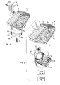
- a modular lighting unit according to the present invention, is shown at 10.
- the lighting unit 10 has a case 12 with a peripheral wall 14 extending around a light chamber 16 within which a light source 18 (Fig. 8) resides.
- Light from the source 18 projects forwardly through a striped lens 20 at the forward portion of the case 12.
- a suitable construction for the lens 20 is described in my U.S. Patent No. 4,586,116. However, it is not necessary that the lens 20 be other than clear or translucent. In fact, the lens 20 could be altogether eliminated.
- Light projecting rearwardly from the light source 18 is redirected forwardly by a reflector 22 at the rear of the case 12.
- the reflector 22 is likewise optional.
- a mounting base 24 defines a cradle at 26 for the bottom 28 of the module 10.
- the mounting base 24 provides a pedestal/foundation for the module 10 upon a support 30, as shown generically at 30 in Fig. 7.
- the case 12 has peripherally spaced, elongate ribs 30 extending in a fore and aft direction, with there being recesses 32 defined between adjacent ribs 30.
- Each rib 30 has oppositely facing side surfaces 34, 36 which diverge away from the case 12.
- the recesses 32 have a complementary shape to accept a rib on a like module 10.
- the ribs 30 and recesses 32 are spaced equidistantly so as to mesh with ribs 30 and recesses 32 on an adjoining, like module 10 in a plurality of different relative positions.
- the wall 14 on each case 12 has four flat surface portions 38, 40, 42 and 44 which can be flushly abutted to any of the flat surfaces 38, 40, 42, 44 on a like module 10 to be joined thereto.
- the surfaces 38, 40, 42, 44 cooperatively define a diamond shape.
- the peripheral wall 14 could have other shapes, it is desirable that at least one of the flat surfaces 38, 40, 42, 44 extends other than fully vertically or horizontally to facilitate connection to another module 10.
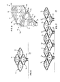
- the angle a of the surface 42 on the lower module 10 is chosen to be equal to the angle a1 of the surface 40 on the superjacent module 10 so that with the modules 10 stacked as shown in Fig. 8, the two modules 10 have the same orientation, i.e with one upright, the other module attached thereto is upright.
- the upper module 10 is held in cantilever fashion from the wall surface 42 on the lower module 10 through the meshing ribs 30. Since the ribs 30 are spaced equidistantly along the surfaces 40, 42, the two modules 10 can be connected in a plurality of different positions along the line of the double-headed arrow 46.
- the arrangement of the ribs 30 and recesses 32 is such that the modules 10 that are to be joined can be relatively positioned, one in front of the other, and moved towards and against each other in a fore and aft direction to mesh the ribs 30.
- a screw or other type of wedge 48 (Fig. 12) can be directed into a bore 50 extending lengthwise into or through one of the ribs 30 to progressively effect a lateral expansion thereof, as indicated by the bowed side surface 34 shown in phantom lines in Fig. 12. This effectively locks adjacent ribs 30 on the joined modules 10 to prevent inadvertent separation of the joined modules 10.
- the modules 10 can be rigidly meshed in clusters in a variety of different attractive and functional shapes.
- Fig. 6 four modules, designated A, B, C and D, are shown assembled together to define a larger diamond shape.
- the module A is carried on a mounting base 24 and connected to modules B and D.
- the uppermost module C is connected to both the modules B and D.
- This structure affords a self-rigidifying arrangement by reason of the interlocking of the modules A, B, C and D.
- Additional modules can be stacked upon the modules B, C, D and each other to construct a further desired shape.
- FIG. 7 nine modules are shown, lettered EM, arranged in a different configuration.
- the lowermost modules E, F, G and H are each received in a mounting base 24 which mounting bases 24 are fixed to an underlying support 30.
- the end modules M, I are each supported in cantilever fashion from a single module E, H, respectively.
- the other modules L, K, J are each connected to two modules.
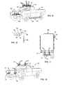
- This interlocking arrangement permits a reinforced, sturdy assembly of modules 10 across a substantial width, as upon the cab 50 of a pickup truck 52, shown in Fig. 9.
- the support 30 can be the vehicle 52 itself or a bracket which is attached to the vehicle 52.
- the mounting bases 24 are attached directly to the vehicle 52.
- modules 10 are shown in front of the grill 54 on the front of the vehicle 52 on the bumper 56.
- the modules 10 are stacked one layer higher than the arrangement shown in Fig. 7.
- the joined modules 10 can be downsized and used as running lights, as on a semi-truck/trailer, shown at 58 in Fig. 11.
- the single modules 10 are shown to be used as brake and turn signal lights for the semi-truck/trailer 58.
- a further downsized version of the module 10 is shown at 60 in Fig. 9 along the edge of a running board 62 on the vehicle 52.
- the modules 10 can be simply joined like building blocks to produce an overall desired size and shape.
- the angular arrangement of the surfaces 38, 40, 42, 44 facilitates stacking, provides a rigid cantilevered support between adjacent modules 10, provides a rigid connection between two joined modules, and allows unique shapes to be created at the point of use by a consumer.
- the consumer can disassemble and reassemble the modules 10 in a desired shape.
- the ribbed arrangement of the case 12 also facilitates connection of the case 12 to the mounting base 24.
- the mounting base 24 is generally L-shaped with a vertically extending wall 64 and a horizontally extending wall 66.
- the wall 66 has ribs 68 and recesses 70 corresponding to the ribs 30 and recesses 32 in terms of size and spacing.
- the horizontal wall 66 has a V shape corresponding to the bottom wall of the case 12.
- the module 10 can thus be press fit from front to rear into operative engagement with the mounting base 24. In that operative position, the rear wall 72 of the case resides in close proximity to the vertically extending wall 64 on the mounting base 24.
- the mounting base 24 has an undercut 74 to accept a mounting plate 76 having ribs 78 which can be slid vertically into mesh with ribs (not shown) on the rear wall 72 of the case 12.
- a fastener in the form of a screw 80, can be directed through the wall 64, the plate 76 and into the case rear wall 82 to prevent separation of the module 10 from the mounting base 24. Disassembly of the module 10 from the mounting base 24 can be accomplished by reversing the above steps.
- a further aspect of the invention is the provision of a levelling means at 82 by which the attitude of the combined module 10 and mounting base 24 can be altered relative to the support 30 on which they are carried.
- a pair of sloped disks 84, 86 are placed in overlying relationship. In one relative position, the disks 84, 86 cooperatively define a uniform thickness.
- the thickened and thin portions of the disk 84, 86 reside in different relationships, thereby causing the upper surface 90 of the disk 84, which bears on the mounting base 24, to vary in attitude.
- a mounting bolt 92 can be directed through the disks 84, 86 and into the mounting base 24 to fix the relative positions thereof.
- An optional spring 94 can be used to biasably capture the disks 84, 86 against the mounting base 24 so that the relative positions of the disks 84, 86 and mounting base 24 are frictionally maintained before the bolt 92 is tightened to positively fix this relationship.
- FIG. 1 Another aspect of the invention is the provision of a mounting/guide rail 96 to accept a modified form of mounting base, as shown in Fig. 3 at 98.
- the mounting base 98 has an enlarged disk 100 which fits in a slot 102 on the rail 96 to allow the disk 100, and module 10 associated therewith, to be slid along the rail 96.
- a bolt 104 can be directed through any of a number of bores 106 in the rail 96 to extend into the mounting base 98 to fix the position of the mounting base 98 relative to the rail 96 as desired.
Landscapes
- Engineering & Computer Science (AREA)
- Mechanical Engineering (AREA)
- Lighting Device Outwards From Vehicle And Optical Signal (AREA)
- Non-Portable Lighting Devices Or Systems Thereof (AREA)
Applications Claiming Priority (2)
| Application Number | Priority Date | Filing Date | Title |
|---|---|---|---|
| US14581993A | 1993-11-02 | 1993-11-02 | |
| US145819 | 1993-11-02 |
Publications (3)
| Publication Number | Publication Date |
|---|---|
| EP0653327A2 true EP0653327A2 (fr) | 1995-05-17 |
| EP0653327A3 EP0653327A3 (fr) | 1995-11-22 |
| EP0653327B1 EP0653327B1 (fr) | 2001-07-25 |
Family
ID=22514693
Family Applications (1)
| Application Number | Title | Priority Date | Filing Date |
|---|---|---|---|
| EP19940306718 Expired - Lifetime EP0653327B1 (fr) | 1993-11-02 | 1994-09-14 | Unité d'éclairage modulaire |
Country Status (3)
| Country | Link |
|---|---|
| EP (1) | EP0653327B1 (fr) |
| CA (1) | CA2117564C (fr) |
| DE (1) | DE69427803T2 (fr) |
Cited By (5)
| Publication number | Priority date | Publication date | Assignee | Title |
|---|---|---|---|---|
| EP0781081A1 (fr) * | 1995-12-20 | 1997-06-25 | Paolo Targetti | Structure de support modulaire de dispositifs électriques, électroniques et d'appareillage lumineux |
| EP0881118A3 (fr) * | 1997-05-26 | 2000-06-14 | Volkswagen Aktiengesellschaft | Dispositif de fixation pour phare |
| WO2017220749A1 (fr) * | 2016-06-22 | 2017-12-28 | Designquadrat Gbr | Module d'éclairage pour la fourniture d'au moins une fonction feu arrière dans le cas d'un véhicule |
| CN108001341A (zh) * | 2017-12-28 | 2018-05-08 | 温州恒古科技发展有限公司 | 特种车辆用警示灯 |
| EP3808601A1 (fr) * | 2019-10-14 | 2021-04-21 | Teknoware Oy | Module d'éclairage et procédé et dispositif pour assembler un dispositif d'éclairage d'un véhicule à partir des modules d'éclairage |
Families Citing this family (1)
| Publication number | Priority date | Publication date | Assignee | Title |
|---|---|---|---|---|
| DE102012102453B4 (de) * | 2012-03-22 | 2024-02-01 | Dr. Ing. H.C. F. Porsche Aktiengesellschaft | Rückstrahler eines Kraftfahrzeugs |
Family Cites Families (3)
| Publication number | Priority date | Publication date | Assignee | Title |
|---|---|---|---|---|
| DE2024915A1 (de) * | 1970-05-22 | 1971-12-02 | Fichtel F | Fahrtrichtungsanzeiger in Form von Blinkleuchten fur Kraftrader |
| US4764851A (en) * | 1987-02-11 | 1988-08-16 | Itc, Incorporated | Light fixture |
| US4972301A (en) * | 1989-01-18 | 1990-11-20 | Kasboske George C | Vehicle lamp with universal mounting capability |
-
1994
- 1994-08-24 CA CA 2117564 patent/CA2117564C/fr not_active Expired - Fee Related
- 1994-09-14 DE DE1994627803 patent/DE69427803T2/de not_active Expired - Fee Related
- 1994-09-14 EP EP19940306718 patent/EP0653327B1/fr not_active Expired - Lifetime
Cited By (7)
| Publication number | Priority date | Publication date | Assignee | Title |
|---|---|---|---|---|
| EP0781081A1 (fr) * | 1995-12-20 | 1997-06-25 | Paolo Targetti | Structure de support modulaire de dispositifs électriques, électroniques et d'appareillage lumineux |
| US5779354A (en) * | 1995-12-20 | 1998-07-14 | Targetti; Paolo | Modular support structure for electrical and electronic devices and for lighting apparatuses |
| EP0881118A3 (fr) * | 1997-05-26 | 2000-06-14 | Volkswagen Aktiengesellschaft | Dispositif de fixation pour phare |
| WO2017220749A1 (fr) * | 2016-06-22 | 2017-12-28 | Designquadrat Gbr | Module d'éclairage pour la fourniture d'au moins une fonction feu arrière dans le cas d'un véhicule |
| CN108001341A (zh) * | 2017-12-28 | 2018-05-08 | 温州恒古科技发展有限公司 | 特种车辆用警示灯 |
| CN108001341B (zh) * | 2017-12-28 | 2024-01-26 | 温州商宇科技有限公司 | 特种车辆用警示灯 |
| EP3808601A1 (fr) * | 2019-10-14 | 2021-04-21 | Teknoware Oy | Module d'éclairage et procédé et dispositif pour assembler un dispositif d'éclairage d'un véhicule à partir des modules d'éclairage |
Also Published As
| Publication number | Publication date |
|---|---|
| DE69427803D1 (de) | 2001-08-30 |
| DE69427803T2 (de) | 2002-01-17 |
| EP0653327B1 (fr) | 2001-07-25 |
| CA2117564C (fr) | 1999-09-28 |
| EP0653327A3 (fr) | 1995-11-22 |
| CA2117564A1 (fr) | 1995-05-03 |
Similar Documents
| Publication | Publication Date | Title |
|---|---|---|
| US6123441A (en) | Modular lighting unit | |
| US4738464A (en) | Combined bumper and receiver trailer hitch assembly | |
| JP3870361B2 (ja) | 前照灯取付装置 | |
| US5246120A (en) | Bicycle rack | |
| USD343605S (en) | Cab bumper with headlights | |
| US20050280269A1 (en) | Bumper having separate energy absorber and fascia support | |
| EP0653327B1 (fr) | Unité d'éclairage modulaire | |
| US10046721B2 (en) | Vehicle sport bar with removable decorative panels | |
| USD294975S (en) | Combined license plate bracket and vehicle back-up signal lights | |
| US20200011500A1 (en) | Quick Adjust Vehicle Headlight Assembly | |
| US6443605B1 (en) | Attitude adjusting structure for a lighting unit | |
| US5409289A (en) | Cross member assembly for a vehicle frame | |
| US5803200A (en) | Adjustable pivot axis for "The missing link" swivel for four-link rigid axle suspensions | |
| USD280497S (en) | Combined air deflector and step for mounting below the front bumper of a truck | |
| USD345273S (en) | Weaponry bracket assembly | |
| US4532577A (en) | Adjustable seating arrangement for a tail lamp assembly | |
| CN1342573A (zh) | 车辆用灯具 | |
| US4970809A (en) | License plate display panel | |
| USD1105526S1 (en) | Car light | |
| US4406490A (en) | License plate holder | |
| USD333995S (en) | Combined tilt monitor and signal for vehicle | |
| JPH0339324Y2 (fr) | ||
| GB2265583A (en) | A construction for installing automobile bumpers | |
| CN221794389U (zh) | 仪表总成以及车辆 | |
| JPH0515192Y2 (fr) |
Legal Events
| Date | Code | Title | Description |
|---|---|---|---|
| PUAI | Public reference made under article 153(3) epc to a published international application that has entered the european phase |
Free format text: ORIGINAL CODE: 0009012 |
|
| AK | Designated contracting states |
Kind code of ref document: A2 Designated state(s): DE FR GB IT |
|
| PUAL | Search report despatched |
Free format text: ORIGINAL CODE: 0009013 |
|
| AK | Designated contracting states |
Kind code of ref document: A3 Designated state(s): DE FR GB IT |
|
| 17P | Request for examination filed |
Effective date: 19960429 |
|
| 17Q | First examination report despatched |
Effective date: 19970513 |
|
| GRAG | Despatch of communication of intention to grant |
Free format text: ORIGINAL CODE: EPIDOS AGRA |
|
| GRAG | Despatch of communication of intention to grant |
Free format text: ORIGINAL CODE: EPIDOS AGRA |
|
| GRAH | Despatch of communication of intention to grant a patent |
Free format text: ORIGINAL CODE: EPIDOS IGRA |
|
| GRAH | Despatch of communication of intention to grant a patent |
Free format text: ORIGINAL CODE: EPIDOS IGRA |
|
| GRAA | (expected) grant |
Free format text: ORIGINAL CODE: 0009210 |
|
| AK | Designated contracting states |
Kind code of ref document: B1 Designated state(s): DE FR GB IT |
|
| REF | Corresponds to: |
Ref document number: 69427803 Country of ref document: DE Date of ref document: 20010830 |
|
| ET | Fr: translation filed | ||
| REG | Reference to a national code |
Ref country code: GB Ref legal event code: IF02 |
|
| PLBE | No opposition filed within time limit |
Free format text: ORIGINAL CODE: 0009261 |
|
| STAA | Information on the status of an ep patent application or granted ep patent |
Free format text: STATUS: NO OPPOSITION FILED WITHIN TIME LIMIT |
|
| 26N | No opposition filed | ||
| PGFP | Annual fee paid to national office [announced via postgrant information from national office to epo] |
Ref country code: GB Payment date: 20050314 Year of fee payment: 11 |
|
| PGFP | Annual fee paid to national office [announced via postgrant information from national office to epo] |
Ref country code: DE Payment date: 20050324 Year of fee payment: 11 |
|
| PGFP | Annual fee paid to national office [announced via postgrant information from national office to epo] |
Ref country code: FR Payment date: 20050330 Year of fee payment: 11 |
|
| PG25 | Lapsed in a contracting state [announced via postgrant information from national office to epo] |
Ref country code: IT Free format text: LAPSE BECAUSE OF NON-PAYMENT OF DUE FEES;WARNING: LAPSES OF ITALIAN PATENTS WITH EFFECTIVE DATE BEFORE 2007 MAY HAVE OCCURRED AT ANY TIME BEFORE 2007. THE CORRECT EFFECTIVE DATE MAY BE DIFFERENT FROM THE ONE RECORDED. Effective date: 20050914 Ref country code: GB Free format text: LAPSE BECAUSE OF NON-PAYMENT OF DUE FEES Effective date: 20050914 |
|
| PG25 | Lapsed in a contracting state [announced via postgrant information from national office to epo] |
Ref country code: DE Free format text: LAPSE BECAUSE OF NON-PAYMENT OF DUE FEES Effective date: 20060401 |
|
| GBPC | Gb: european patent ceased through non-payment of renewal fee |
Effective date: 20050914 |
|
| PG25 | Lapsed in a contracting state [announced via postgrant information from national office to epo] |
Ref country code: FR Free format text: LAPSE BECAUSE OF NON-PAYMENT OF DUE FEES Effective date: 20050930 |