EP0653330B1 - Vorrichtung zum Transport von Lasten an Kraftfahrzeugen mit Kugelkopfkupplung - Google Patents
Vorrichtung zum Transport von Lasten an Kraftfahrzeugen mit KugelkopfkupplungInfo
- Publication number
- EP0653330B1 EP0653330B1 EP94116291A EP94116291A EP0653330B1 EP 0653330 B1 EP0653330 B1 EP 0653330B1 EP 94116291 A EP94116291 A EP 94116291A EP 94116291 A EP94116291 A EP 94116291A EP 0653330 B1 EP0653330 B1 EP 0653330B1
- Authority
- EP
- European Patent Office
- Prior art keywords
- travel
- spindle
- supporting arm
- carrying arm
- sleeve
- Prior art date
- Legal status (The legal status is an assumption and is not a legal conclusion. Google has not performed a legal analysis and makes no representation as to the accuracy of the status listed.)
- Expired - Lifetime
Links
- 230000008878 coupling Effects 0.000 claims description 8
- 238000010168 coupling process Methods 0.000 claims description 8
- 238000005859 coupling reaction Methods 0.000 claims description 8
- 230000001747 exhibiting effect Effects 0.000 claims 1
- 238000004806 packaging method and process Methods 0.000 claims 1
- 238000012856 packing Methods 0.000 description 1
Images


Classifications
-
- B—PERFORMING OPERATIONS; TRANSPORTING
- B60—VEHICLES IN GENERAL
- B60R—VEHICLES, VEHICLE FITTINGS, OR VEHICLE PARTS, NOT OTHERWISE PROVIDED FOR
- B60R9/00—Supplementary fittings on vehicle exterior for carrying loads, e.g. luggage, sports gear or the like
- B60R9/06—Supplementary fittings on vehicle exterior for carrying loads, e.g. luggage, sports gear or the like at vehicle front or rear
Definitions
- the invention relates to a device for transporting loads on the rear of motor vehicles, which are provided with a ball head coupling by means of a support arm which is directed horizontally against the direction of travel.
- the invention has for its object to provide a device of the type described above for transporting loads, which can also be used when there are obstacles such as spare wheels or the like on the rear of the vehicle and also to enable the versatile use of such devices and which allow easy and handy assembly.
- the object of the invention which achieves the stated object, is a device for transporting loads on the rear of motor vehicles which are provided with a ball head coupling by means of a support arm directed horizontally against the direction of travel. It consists of a rod, which is provided with means for fastening it transversely to the direction of travel on a ball coupling, the rod having two stops symmetrical to the fastening means.
- a tube piece in the form of a cap overlapping the ball head is firmly attached to the support arm and
- an obliquely downward-pointing support bracket is attached, which has a recess at its lower end with which the support bracket rests positively on the crossbar outside the stops as soon as the support arm is in its intended position and that in the support arm in an obliquely downward direction of the sleeve, which projects above the support arm upwards, a spindle with an external thread, which by actuating a handwheel located at the upper end of the sleeve with a in the Spindle thread engaging internal thread can be moved longitudinally against the sleeve and that the spindle carries at its lower end a flat band, which is also deformed at its lower end in the direction of travel to a semicircle, which is flush between the by means of the spindle and when the pipe piece is seated on the ball head Stops around the crossbar can be brought into contact.
- the particular advantage of the device according to the invention can be seen in the fact that it can be attached to the ball head in a few simple steps.
- a horizontally extending pin is provided in a further development of the invention which secures the flat strip against rotation.
- the support arm consists of a hollow profile with a triangular or polygonal or also round cross section and either by telescopically inserting one or, in succession, several hollow profiles of correspondingly lower dimensions or can be extended by placing hollow sections of the same dimensions together using sleeves guided inside or outside the hollow profiles.
- components for the transport of various loads are pushed and locked on the support arm or the hollow profiles serving as extensions, or are firmly connected to the hollow profile.
- components for transporting bicycles, skis, sailing or surfing devices or for transporting packing containers can be placed on individual hollow profile parts and fastened thereon, or the hollow profile parts are firmly connected to such components and are optionally attached to the support arm as required .
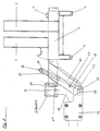
- FIGS. 1 and 2 show how components 2 and 3 for the transport of certain loads, which are shown generally on a hollow profile 1, are fixed by means of screws 4, 5 and 6. These figures also show how the support arm 7 is attached to the vehicle by means of a spherical head coupling.
- the support arm 7 is firmly connected to the pipe section 9, which engages over the ball head 8 in the form of a cap.
- a rod 13 extending transversely to the direction of travel and having two stops 22 is fixedly mounted with clamping pieces 12.
- a spindle 16 with an external thread which can be moved longitudinally against the sleeve 15 by actuating a handwheel 17 located at the upper end of the sleeve 15 with an internal thread engaging in the spindle thread, and that the spindle 16 has a flat strip at its lower end 18 carries, which is deformed at its lower end in the direction of travel to a semicircle 19 which can be brought flush against the rod 13 by means of the spindle 16 and with the pipe piece 9 seated on the ball head 8 between the stops 22.
- a bore 21 can be provided in the pipe section 9 for attaching a security device against theft or unintentional lifting.
- Figure 3 shows the two possibilities according to the invention to extend the support arm 7. According to sub-figure 3a, this is done by the fact that hollow sections 23 and 24 of correspondingly lower dimensions can be telescopically inserted or extracted into the support arm 7. According to FIG. 3b, a hollow section 25 of the same profile is attached to the support arm 7 and is connected to the support arm 7 by means of an inserted sleeve 26. In both cases, the individual parts are fixed against each other in the direction of travel and the opposite direction.
Landscapes
- Engineering & Computer Science (AREA)
- Mechanical Engineering (AREA)
- Fittings On The Vehicle Exterior For Carrying Loads, And Devices For Holding Or Mounting Articles (AREA)
- Load-Engaging Elements For Cranes (AREA)
Applications Claiming Priority (2)
| Application Number | Priority Date | Filing Date | Title |
|---|---|---|---|
| DE4337006A DE4337006C2 (de) | 1993-10-29 | 1993-10-29 | Vorrichtung zum Transport von Lasten an Kraftfahrzeugen mit Kugelkopfkupplungen |
| DE4337006 | 1993-10-29 |
Publications (2)
| Publication Number | Publication Date |
|---|---|
| EP0653330A1 EP0653330A1 (de) | 1995-05-17 |
| EP0653330B1 true EP0653330B1 (de) | 1996-05-08 |
Family
ID=6501373
Family Applications (1)
| Application Number | Title | Priority Date | Filing Date |
|---|---|---|---|
| EP94116291A Expired - Lifetime EP0653330B1 (de) | 1993-10-29 | 1994-10-15 | Vorrichtung zum Transport von Lasten an Kraftfahrzeugen mit Kugelkopfkupplung |
Country Status (4)
| Country | Link |
|---|---|
| EP (1) | EP0653330B1 (da) |
| AT (1) | ATE137708T1 (da) |
| DE (1) | DE4337006C2 (da) |
| DK (1) | DK0653330T3 (da) |
Cited By (2)
| Publication number | Priority date | Publication date | Assignee | Title |
|---|---|---|---|---|
| EP2759421B1 (de) | 2013-01-25 | 2020-01-22 | ACPS Automotive GmbH | Anhängekupplung und Lastenträgereinrichtung für eine Anhängekupplung |
| EP2962899B1 (de) | 2014-06-30 | 2020-02-26 | ACPS Automotive GmbH | Anhängekupplung und lastenträgereinrichtung für eine anhängekupplung |
Families Citing this family (5)
| Publication number | Priority date | Publication date | Assignee | Title |
|---|---|---|---|---|
| FR2780009B1 (fr) * | 1998-06-18 | 2002-04-19 | Robert Annet Serre | Dispositif se fixant en deux points sur le col de cygne d'attelage et permettant de recevoir un accessoire de portage |
| DE19856848C2 (de) * | 1998-12-09 | 2001-07-12 | Mft Transp Systeme Gmbh | Kupplungsgebundener Fahrzeugheckträger |
| DE102006036983B4 (de) * | 2006-02-24 | 2021-08-05 | Volkswagen Ag | Fahrradträger |
| EP3575113B1 (en) * | 2018-05-23 | 2020-04-29 | Thule Sweden AB | Load carrier coupling |
| GB2588911B (en) * | 2019-11-13 | 2022-06-15 | Noko Design Tech Manufacture Ltd | Modular carrying system |
Family Cites Families (5)
| Publication number | Priority date | Publication date | Assignee | Title |
|---|---|---|---|---|
| US3251520A (en) * | 1964-04-23 | 1966-05-17 | William E Van Dyke | Rollout carrier |
| US4029245A (en) * | 1976-01-14 | 1977-06-14 | Berlin David L | Automobile material carrier |
| US4369902A (en) * | 1981-02-06 | 1983-01-25 | Steve Lampeas | Retractable load carrier for vehicles |
| DE3300439A1 (de) * | 1983-01-08 | 1984-07-12 | Rodiac Intercessor Ltd., Zug | Kupplungseinheit zur stabilen verbindung mit einem ueblichen zughaken |
| GB8620410D0 (en) * | 1986-08-21 | 1986-10-01 | Philpott J | Luggage carrier |
-
1993
- 1993-10-29 DE DE4337006A patent/DE4337006C2/de not_active Expired - Fee Related
-
1994
- 1994-10-15 DK DK94116291.9T patent/DK0653330T3/da active
- 1994-10-15 AT AT94116291T patent/ATE137708T1/de not_active IP Right Cessation
- 1994-10-15 EP EP94116291A patent/EP0653330B1/de not_active Expired - Lifetime
Cited By (3)
| Publication number | Priority date | Publication date | Assignee | Title |
|---|---|---|---|---|
| EP2759421B1 (de) | 2013-01-25 | 2020-01-22 | ACPS Automotive GmbH | Anhängekupplung und Lastenträgereinrichtung für eine Anhängekupplung |
| EP4209365A1 (de) * | 2013-01-25 | 2023-07-12 | ACPS Automotive GmbH | Anhängekupplung und lastenträgereinrichtung für eine anhängekupplung |
| EP2962899B1 (de) | 2014-06-30 | 2020-02-26 | ACPS Automotive GmbH | Anhängekupplung und lastenträgereinrichtung für eine anhängekupplung |
Also Published As
| Publication number | Publication date |
|---|---|
| DK0653330T3 (da) | 1996-09-23 |
| DE4337006A1 (de) | 1995-05-04 |
| EP0653330A1 (de) | 1995-05-17 |
| DE4337006C2 (de) | 1998-05-20 |
| ATE137708T1 (de) | 1996-05-15 |
Similar Documents
| Publication | Publication Date | Title |
|---|---|---|
| EP0503305A1 (de) | Dachgepäckträger für Kraftfahrzeuge mit Dachreling | |
| DE4208064C2 (da) | ||
| EP0653330B1 (de) | Vorrichtung zum Transport von Lasten an Kraftfahrzeugen mit Kugelkopfkupplung | |
| DE4108656C1 (da) | ||
| DE10309327A1 (de) | Gepäckträger an einem Kraftfahrzeug | |
| EP0939005A1 (de) | Vorrichtung zum Befestigen von Gegenständen im Gepäckraum eines Kraftfahrzeuges | |
| WO1997008017A1 (de) | Dachträger zur befestigung eines fahrrads | |
| DE202004003423U1 (de) | Lastenträger für Kraftfahrzeuge | |
| DE102011010578A1 (de) | Vorrichtung zur Befestigung eines Fahrrades in einem Fahrzeuginnenraum | |
| DE19620486A1 (de) | Fahrradhalter für PKW zum Transportieren von Fahrrädern | |
| EP0005811A1 (de) | Kraftfahrzeug-Dachträger für die Befestigung von Skiern und anderem Transportgut | |
| DE3642864C1 (en) | Fastening device for roofracks on motor vehicle bodies | |
| DE4211180A1 (de) | Formschlüssiges und einstellbares Verbindungsteil zum Anschließen von freiauskragenden Gepäckträgern an KFZ-Anhängerkupplungen mit Kugelkopf | |
| DE4239697C2 (de) | Vorrichtung zum Festlegen von Gegenständen im Griffbereich des Führers eines Kraftfahrzeuges, wie Handapparat eines Mobiltelefons, Getränkeflasche oder dgl. | |
| DE10122560B4 (de) | Kraftfahrzeug-Heckträger mit Adapter | |
| DE3635992A1 (de) | Einrichtung zur befestigung eines rueckhaltesystems | |
| DE4424612A1 (de) | Fahrzeug mit einem Heckgepäckträger | |
| DE10236774B4 (de) | Befestigungsträger für den Fahrzeuginnenraum | |
| DE102021207883B3 (de) | Trägersystem für ein Zweirad | |
| DE19836852C1 (de) | Lastenträger eines Dachträgersystems für Kraftfahrzeuge | |
| DE102017001152A1 (de) | Fahrradträger zur heckseitigen Anbringung an einem Kraftfahrzeug | |
| DE9210885U1 (de) | Formschlüssiges und einstellbares Verbindungsteil zum Anschließen von freiauskragenden Gepäckträgern an KFZ-Anhängerkupplungen mit Kugelkopf | |
| DE20216172U1 (de) | Lastträgervorrichtung für ein Fahrzeug | |
| DE9206306U1 (de) | Dachträger | |
| DE20205946U1 (de) | Transportanhänger |
Legal Events
| Date | Code | Title | Description |
|---|---|---|---|
| PUAI | Public reference made under article 153(3) epc to a published international application that has entered the european phase |
Free format text: ORIGINAL CODE: 0009012 |
|
| AK | Designated contracting states |
Kind code of ref document: A1 Designated state(s): AT BE CH DK FR GB IT LI NL SE |
|
| 17P | Request for examination filed |
Effective date: 19950620 |
|
| 17Q | First examination report despatched |
Effective date: 19950719 |
|
| GRAA | (expected) grant |
Free format text: ORIGINAL CODE: 0009210 |
|
| AK | Designated contracting states |
Kind code of ref document: B1 Designated state(s): AT BE CH DK FR GB IT LI NL SE |
|
| REF | Corresponds to: |
Ref document number: 137708 Country of ref document: AT Date of ref document: 19960515 Kind code of ref document: T |
|
| ITF | It: translation for a ep patent filed | ||
| REG | Reference to a national code |
Ref country code: CH Ref legal event code: NV Representative=s name: PATENTANWAELTE GEORG ROEMPLER UND ALDO ROEMPLER |
|
| GBT | Gb: translation of ep patent filed (gb section 77(6)(a)/1977) |
Effective date: 19960708 |
|
| ET | Fr: translation filed | ||
| REG | Reference to a national code |
Ref country code: DK Ref legal event code: T3 |
|
| PLBE | No opposition filed within time limit |
Free format text: ORIGINAL CODE: 0009261 |
|
| STAA | Information on the status of an ep patent application or granted ep patent |
Free format text: STATUS: NO OPPOSITION FILED WITHIN TIME LIMIT |
|
| 26N | No opposition filed | ||
| REG | Reference to a national code |
Ref country code: GB Ref legal event code: IF02 |
|
| PGFP | Annual fee paid to national office [announced via postgrant information from national office to epo] |
Ref country code: AT Payment date: 20050831 Year of fee payment: 12 |
|
| PGFP | Annual fee paid to national office [announced via postgrant information from national office to epo] |
Ref country code: GB Payment date: 20051012 Year of fee payment: 12 |
|
| PGFP | Annual fee paid to national office [announced via postgrant information from national office to epo] |
Ref country code: BE Payment date: 20051019 Year of fee payment: 12 |
|
| PGFP | Annual fee paid to national office [announced via postgrant information from national office to epo] |
Ref country code: DK Payment date: 20051026 Year of fee payment: 12 |
|
| PGFP | Annual fee paid to national office [announced via postgrant information from national office to epo] |
Ref country code: CH Payment date: 20051229 Year of fee payment: 12 |
|
| PG25 | Lapsed in a contracting state [announced via postgrant information from national office to epo] |
Ref country code: AT Free format text: LAPSE BECAUSE OF NON-PAYMENT OF DUE FEES Effective date: 20061015 |
|
| PGFP | Annual fee paid to national office [announced via postgrant information from national office to epo] |
Ref country code: SE Payment date: 20061026 Year of fee payment: 13 |
|
| PGFP | Annual fee paid to national office [announced via postgrant information from national office to epo] |
Ref country code: FR Payment date: 20061030 Year of fee payment: 13 |
|
| PG25 | Lapsed in a contracting state [announced via postgrant information from national office to epo] |
Ref country code: LI Free format text: LAPSE BECAUSE OF NON-PAYMENT OF DUE FEES Effective date: 20061031 Ref country code: DK Free format text: LAPSE BECAUSE OF NON-PAYMENT OF DUE FEES Effective date: 20061031 Ref country code: CH Free format text: LAPSE BECAUSE OF NON-PAYMENT OF DUE FEES Effective date: 20061031 |
|
| PGFP | Annual fee paid to national office [announced via postgrant information from national office to epo] |
Ref country code: NL Payment date: 20061031 Year of fee payment: 13 Ref country code: IT Payment date: 20061031 Year of fee payment: 13 |
|
| REG | Reference to a national code |
Ref country code: CH Ref legal event code: PL |
|
| GBPC | Gb: european patent ceased through non-payment of renewal fee |
Effective date: 20061015 |
|
| PG25 | Lapsed in a contracting state [announced via postgrant information from national office to epo] |
Ref country code: GB Free format text: LAPSE BECAUSE OF NON-PAYMENT OF DUE FEES Effective date: 20061015 |
|
| BERE | Be: lapsed |
Owner name: *BUSSLER PAUL Effective date: 20061031 |
|
| EUG | Se: european patent has lapsed | ||
| NLV4 | Nl: lapsed or anulled due to non-payment of the annual fee |
Effective date: 20080501 |
|
| REG | Reference to a national code |
Ref country code: FR Ref legal event code: ST Effective date: 20080630 |
|
| PG25 | Lapsed in a contracting state [announced via postgrant information from national office to epo] |
Ref country code: SE Free format text: LAPSE BECAUSE OF NON-PAYMENT OF DUE FEES Effective date: 20071016 Ref country code: NL Free format text: LAPSE BECAUSE OF NON-PAYMENT OF DUE FEES Effective date: 20080501 |
|
| PG25 | Lapsed in a contracting state [announced via postgrant information from national office to epo] |
Ref country code: FR Free format text: LAPSE BECAUSE OF NON-PAYMENT OF DUE FEES Effective date: 20071031 |
|
| PG25 | Lapsed in a contracting state [announced via postgrant information from national office to epo] |
Ref country code: IT Free format text: LAPSE BECAUSE OF NON-PAYMENT OF DUE FEES Effective date: 20071015 Ref country code: BE Free format text: LAPSE BECAUSE OF FAILURE TO SUBMIT A TRANSLATION OF THE DESCRIPTION OR TO PAY THE FEE WITHIN THE PRESCRIBED TIME-LIMIT Effective date: 20061031 |