EP0653364B1 - Verbesserte Stielzusammensetzung - Google Patents
Verbesserte Stielzusammensetzung Download PDFInfo
- Publication number
- EP0653364B1 EP0653364B1 EP94308031A EP94308031A EP0653364B1 EP 0653364 B1 EP0653364 B1 EP 0653364B1 EP 94308031 A EP94308031 A EP 94308031A EP 94308031 A EP94308031 A EP 94308031A EP 0653364 B1 EP0653364 B1 EP 0653364B1
- Authority
- EP
- European Patent Office
- Prior art keywords
- shaft
- shaft part
- shaft assembly
- pin means
- assembly according
- Prior art date
- Legal status (The legal status is an assumption and is not a legal conclusion. Google has not performed a legal analysis and makes no representation as to the accuracy of the status listed.)
- Expired - Lifetime
Links
- 230000013011 mating Effects 0.000 claims description 22
- 230000000717 retained effect Effects 0.000 claims description 2
- 238000007688 edging Methods 0.000 description 2
- 230000000694 effects Effects 0.000 description 2
- 238000009966 trimming Methods 0.000 description 2
- 238000004519 manufacturing process Methods 0.000 description 1
Images


Classifications
-
- A—HUMAN NECESSITIES
- A01—AGRICULTURE; FORESTRY; ANIMAL HUSBANDRY; HUNTING; TRAPPING; FISHING
- A01D—HARVESTING; MOWING
- A01D34/00—Mowers; Mowing apparatus of harvesters
- A01D34/835—Mowers; Mowing apparatus of harvesters specially adapted for particular purposes
- A01D34/90—Mowers; Mowing apparatus of harvesters specially adapted for particular purposes for carrying by the operator
- A01D34/902—Ergonomic provisions
-
- B—PERFORMING OPERATIONS; TRANSPORTING
- B25—HAND TOOLS; PORTABLE POWER-DRIVEN TOOLS; MANIPULATORS
- B25G—HANDLES FOR HAND IMPLEMENTS
- B25G1/00—Handle constructions
- B25G1/04—Handle constructions telescopic; extensible; sectional
-
- Y—GENERAL TAGGING OF NEW TECHNOLOGICAL DEVELOPMENTS; GENERAL TAGGING OF CROSS-SECTIONAL TECHNOLOGIES SPANNING OVER SEVERAL SECTIONS OF THE IPC; TECHNICAL SUBJECTS COVERED BY FORMER USPC CROSS-REFERENCE ART COLLECTIONS [XRACs] AND DIGESTS
- Y10—TECHNICAL SUBJECTS COVERED BY FORMER USPC
- Y10S—TECHNICAL SUBJECTS COVERED BY FORMER USPC CROSS-REFERENCE ART COLLECTIONS [XRACs] AND DIGESTS
- Y10S56/00—Harvesters
- Y10S56/18—Handles
-
- Y—GENERAL TAGGING OF NEW TECHNOLOGICAL DEVELOPMENTS; GENERAL TAGGING OF CROSS-SECTIONAL TECHNOLOGIES SPANNING OVER SEVERAL SECTIONS OF THE IPC; TECHNICAL SUBJECTS COVERED BY FORMER USPC CROSS-REFERENCE ART COLLECTIONS [XRACs] AND DIGESTS
- Y10—TECHNICAL SUBJECTS COVERED BY FORMER USPC
- Y10T—TECHNICAL SUBJECTS COVERED BY FORMER US CLASSIFICATION
- Y10T403/00—Joints and connections
- Y10T403/70—Interfitted members
- Y10T403/7047—Radially interposed shim or bushing
- Y10T403/7051—Wedging or camming
-
- Y—GENERAL TAGGING OF NEW TECHNOLOGICAL DEVELOPMENTS; GENERAL TAGGING OF CROSS-SECTIONAL TECHNOLOGIES SPANNING OVER SEVERAL SECTIONS OF THE IPC; TECHNICAL SUBJECTS COVERED BY FORMER USPC CROSS-REFERENCE ART COLLECTIONS [XRACs] AND DIGESTS
- Y10—TECHNICAL SUBJECTS COVERED BY FORMER USPC
- Y10T—TECHNICAL SUBJECTS COVERED BY FORMER US CLASSIFICATION
- Y10T403/00—Joints and connections
- Y10T403/70—Interfitted members
- Y10T403/7062—Clamped members
- Y10T403/7064—Clamped members by wedge or cam
- Y10T403/7066—Clamped members by wedge or cam having actuator
- Y10T403/7071—Lever actuator
Definitions
- the present invention relates to a shaft assembly for a tool, in particular to a shaft assembly for a vegetation cutter, in particular a vegetation cutter that cuts by means of a filament or strip that is rotated rapidly about an axis that may be either substantially vertical or substantially horizontal, depending upon the application.
- Vegetation cutters of this type are known, in which the cutting head can be rotated between a trimming mode, in which the filament or strip is rotated about a substantially vertical axis, and an edging mode in which the filament or strip is rotated about a substantially horizontal axis. It is a disadvantage of these known trimmers that the effective shaft length, that is the length between the handle and the working head, remains substantially the same whichever mode is used, and cannot be adjusted for individual operators of different heights.
- US-A-4,052,789 discloses a line trimmer which comprises a handle attached to a cutting head via a shaft.
- the shaft comprises attitude adjusting means which connects a top part of the shaft to a bottom part of the shaft and which enables the user to rotate the cutting head about the longitudinal axis of the shaft in relation to the handle.
- the cutting head is rotated by a user applying a compressional force to the shaft to unlock the attitude adjusting means which is biased into a locking position.
- the attitude adjusting means is unlocked by the axial movement of the top part of the shaft relative to the bottom part of the shaft.
- the top part of the shaft to rotate freely relative to the bottom part, and therefore the user can rotate the top part, and hence the handle, relative to the bottom part, and hence the cutting head, to a preset desired position.
- the user then removes the compressional force allowing the biasing force to lock the attitude adjusting means.
- the attitude adjusting means disclosed in US-A-4,052,789 only enables the handle to be located in one of four angular positions in relation to the cutting head.
- the length of the shaft is telescopically adjustable.
- the present invention provides a shaft assembly for a tool, which assembly is adapted to be arranged between a handle and a working head of the tool and which comprises a first shaft part and a second shaft part, characterised in that;
- the first shaft part preferably comprises first and second mating parts.
- the pin means is preferably retained within the first shaft part and is free to move between a first location in the first shaft part corresponding to a maximum extension of the shaft and a second location in the first shaft part corresponding to minimum extension of the shaft.
- a longitudinal channel extends along a portion of the length of each of the mating parts of the first shaft part, and the pin means is mounted within the assembled first shaft part so that one end of the pin means projects through the channel in the first mating part of the first shaft part, and the other end projects through the channel in the second mating part of the first shaft part.
- the second shaft part preferably comprises first and second mating parts.
- the co-operating receiving means comprise a corresponding radial groove formed in the inside wall of each of the two mating parts and which are preferably sized to engage projecting ends of the pin means.
- Each radial groove is preferably provided with a stop to limit movement of the pin means and hence limit rotation of the first shaft part.
- the end of the second shaft part into which the first shaft part is inserted preferably terminates in a plurality preferably four, of deformable fingers, and a locking ring which is free to rotate between a disengaged and an engaged position, is provided to clamp the fingers in engagement with the first shaft part.
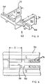
- a vegetation cutter 10 comprises a lower housing (12) connected by a shaft assembly (14) to a handle assembly (16).
- the handle assembly (16) provides a switch (18) for selectively supplying electrical power to an electric motor (not shown) carried within the housing (12).
- a secondary handle 10 is mounted on the handle assembly (16).
- the lower housing (12) carries a cutting head rotatable about an axis passing through the housing (12) and the cutting line (12) extends into a cutting place which is substantially perpendicular to the axis of rotation of housing (12).
- the device can be adjusted in known manner from the trimming mode as shown in Figure 1 to the edging mode by rotation of the lower housing (12) through 180° relative to the handle assembly (16).
- the shaft assembly (14) comprises a first shaft part (26) and a second shaft part (28).
- the first shaft part (26) is of substantially cylindrical cross-section and comprises a lower section (30) which is adapted for attachment to the lower housing (12) and a upper section (32) of reduced cross-section.
- the first shaft part (26) comprises first and second mating parts (34), (36).
- a longitudinal slot (38), (40) extends along the upper portion of the length of each of the mating parts (34), (36), commencing at a point approximately half of the way along the length of the portion of reduced cross-section, and terminating close to the free end of that portion.
- the second shaft part (28) comprises a central section (42) of substantially cylindrical cross-section which terminates at its upper end in a handle assembly (16) and at its lower end with four deformable fingers (44), (44') (44'') (44'').
- the four deformable fingers (44), (44'), (44'') and (44''') are arranged in two opposed pairs.
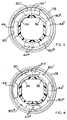
- the second shaft part (28) comprises first and second mating parts (46), (48) each of which is provided on its inner face with a pair of axially offset radial grooves (50), (52) one of which (50) extends from the centre line of the mating part (46), (48) in one direction as far as the outer edge and the second of which (52) extends from the centre line of the mating part (46), (48) in the opposite direction as far as the outer edge.
- Each of the grooves (50), (52) is formed by a pair of parallel upstanding ribs (54), (56) which project from the inner wall of the mating part (46, (48), and is terminated by a short axial rib at the centre line.
- the two mating parts (46), (48) are mirror images of each other, so that when they are assembled to form the second shaft portion (28), the first internal groove (50) extends over half of the internal circumference of the section (42) and the second internal groove (52) extends over the other half of the internal circumference of the section (42).
- the central section (42) of the second shaft portion (28) has an internal diameter which will accept the upper section (32) of the first shaft portion (26).
- the first shaft portion (26) is assembled from its two mating parts (34), (36), and a pin (62)and the pin (62) is trapped between these mating parts (34), (36) with a first arm (64) projecting through slot (38) and an opposite arm (66) projecting through slot (40).
- the pin (62) is free to move along the length of the matching longitudinal slots (38), (40).
- the two arms (64) (66), are offset from one another by the same amount as the radial grooves (50), (52) are relatively offset, so that when the first shaft portion (26) is inserted in the second shaft portion (28) the arms (64), (66) of the pin (62) engage in the radial grooves (50),(52) respectively.
- Relative axial movement of the first shaft portion (26) and the second shaft portion (28) is thus permitted as the pin (62) moves along the length of the longitudinal slots (38), (40).
- Relative radial movement of the first shaft portion (26) and the second shaft portion (28) is permitted as the pin (62) moves within the internal grooves (50), (52) over half of the internal circumference, and is constrained by the short axial ribs at the centre line.
- the pin (62) further comprises extension portions (68) and (70) of right angles to the arms (64) and (66), which terminate in projections (72) and (74) respectively.
- These projections (72), (74) are spaced by a distance (X), (Y) from the corresponding arm (64) and (66) respectively.
- a locking ring (78) is provided to clamp the deformable fingers (44), (44'), (44'') and (44''') in engagement with the first shaft part (26).
- the end of the second shaft part (28) which terminates in the deformable fingers is inserted within the ring (78).
- Cam surfaces (80), (80'), (80'') and (80''') are provided on the inner surface of locking ring (78) for engagement with the corresponding fingers (44), (44'), (44'') and (44''').
- a pair of internal axial ribs are provided on the internal surface of the locking ring (78) close to the end of the ring remote from the cam surfaces (80), (80'), (80''), (80''') for engagement with corresponding external projections (not shown) on the second shaft portion (28) to limit the ability of the ring to rotate relative to the shaft portion.
- Figure 3 shows the locking ring (78) in the clamping position, in which the cam surfaces (80), (80'), (80''), (80''') are in engagement with the deformable fingers (44), (44'), (44'') and (44''') and clamping these fingers against the upper section (32) of the first shaft part (26).
- Notches (76) are provided on the internal surface of the first shaft portion (26) which, in co-operation with the projections (72) and (74), control unwanted relative axial movement of the first and second shaft portions (26), (28) when the locking ring (78) is released and provide an audible indication of the relative axial positions of the first and second shaft portions (26), (28)
- a spring (not shown) may be provided to bias the projections (72) and (74) away from each other and towards the notches (76).
- the shaft assembly in an alternative embodiment of the shaft assembly according to the invention, provision is made for the shaft assembly either to be adjustable both in the axial and radial directions, as in the first embodiment or simply in the radial direction, to allow rotation of the head relative to the handle. It may be desirable to provide both alternative types of adjustment in a range of products, and to use the same clamshells for both models, thus reducing the cost of manufacture.
- the first and second mating parts (34) and (36) of the first shaft portion (26) are modified as shown in Figure 6.
- the first and second mating parts (34) and (36) of the first shaft portion (26) are modified as shown in Figure 6.
- the first and second mating parts (34) and (36) of the first shaft portion (26) are modified as shown in Figure 6.
- at the end of the slot (38), (40) remote from the free end of the upper section (32) are provided with a short cross groove (82) at a distance (Z) less than the pin (62) dimension (X) or (Y) from the end of the slot (38) or (40).
- the shaft portion (26) is for use in a shaft assembly which is adjustable both in the axial and radial directions, then a pin (62) as shown in Figure 5 is used and the assembly and operation are exactly as described for the first embodiment, the cross groove (82) having no effect. If however, the shaft portion (26) is for use in a shaft assembly which is only adjustable in the radial direction, then the pin (62) is replaced by an alternative design of pin in which the extension portions (68) and (70) are reduced in length and the projections (72) and (74) are increased in height, so that the distance between the projections (72) and (74) and the arms (64) and (66) respectively, is equal to or less than the distance (Z) defined above. This has the effect that when the shaft is first assembled, the projections (72) and (74) are trapped within the cross-grooves, and axial movement of the first shaft portion (26) relative to the second shaft portion (28) is no longer possible.
Landscapes
- Engineering & Computer Science (AREA)
- Mechanical Engineering (AREA)
- Life Sciences & Earth Sciences (AREA)
- Environmental Sciences (AREA)
- Harvester Elements (AREA)
- Knives (AREA)
Claims (11)
- Stielanordnung (14) für ein Werkzeug, wobei die Anordnung (14) dazu ausgestaltet ist, um zwischen einem Handgriff (16) und einem Arbeitskopf (12) des Werkzeugs angeordnet zu sein, und ein erstes Stielteil (26) und ein zweites Stielteil (28) aufweist, dadurch gekennzeichnet, daß:eine Stifteinrichtung in dem ersten Stielteil (26) eingesetzt und dazu ausgestaltet ist, mit zusammenwirkenden Aufnahmeeinrichtungen (50, 52) in dem zweiten Stielteil (28) einzugreifen, um zu ermöglichen, daß das erste Stielteil (26) in dem zweiten Stielteil (28) zwischen verschiedenen eingespannten Positionen verschiebbar und verdrehbar ist; undeine Einspanneinrichtung (78) vorgesehen ist, um das zweite Stielteil (28) relativ zu dem ersten Stielteil (26) zu sichern.
- Stielanordnung (14) nach Anspruch 1, dadurch gekennzeichnet, daß das erste Stielteil (26) erste (34) und zweite (36) zusammenpassende Teile enthält.
- Stielanordnung (14) nach Anspruch 2, dadurch gekennzeichnet, daß die Stifteinrichtung (62) in dem ersten Stielteil (26) gehalten und frei zwischen einer ersten Position in dem ersten Stielteil (24), die der maximalen Verlängerung des Stiels (14) entspricht, und einer zweiten Position in dem ersten Stielteil (26) frei bewegbar ist, die der minimalen Verlängerung des Stiels (14) entspricht.
- Stielanordnung (14) nach Anspruch 3, dadurch gekennzeichnet, daß sich ein in Längsrichtung verlaufender Einschnitt (38, 40) entlang eines Bereiches der Länge von jedem der zusammenpassenden Teile (34, 36) des ersten Stielteils (26) erstreckt, und daß die Stifteinrichtung (62) in dem zusammen-gesetzten ersten Stielteil (26) so angebracht ist, daß ein Ende (64) der Stifteinrichtung durch den Einschnitt (38) in dem ersten zusammenpassenden Teil (34) des ersten Stielteils (26) vorsteht, und das andere Ende (66) durch den Einschnitt (40) in dem zweiten zusammenpassenden Teil (36) des ersten Stielteils (26) vorsteht.
- Stielanordnung nach einem der Ansprüche 1 bis 4, dadurch gekennzeichnet, daß das zweite Stielteil (28) erste (46) und zweite (48) zusammenpassende Teile enthält.
- Stielanordnung nach Anspruch 5, dadurch gekennzeichnet, daß die zusammenwirkenden Aufnahmeeinrichtungen (50, 52) eine zugehörige Radialnut aufweisen, die an der Innenwand von jedem der beiden zusammenpassenden Teile (46, 48) des zweiten Stielteils (28) ausgebildet ist.
- Stielanordnung nach Anspruch 6, dadurch gekennzeichnet, daß die Radialnuten (50, 52), die an den Innenwänden des zweiten Stielteils (26) ausgebildet sind, so bemessen sind, um mit den vorstehenden Enden (64, 66) der Stifteinrichtung (62) einzugreifen.
- Stielanordnung nach einem der Ansprüche 6 und 7, dadurch gekennzeichnet, daß jede Radialnut (50, 52) mit einem Anschlag versehen ist, um die Bewegung der Stifteinrichtung und somit die Drehung des ersten Stielteils zu begrenzen.
- Stielanordnung nach einem der Ansprüche 1 bis 8, dadurch gekennzeichnet, daß das Ende des zweiten Stielteils (28), in das das erste Stielteil (26) eingesetzt ist, in einer Anzahl von verformbaren Fingern (44, 44', 44'', 44''') endet, und daß ein Arretierring (78) vorgesehen ist, um die Finger (44, 44', 44'', 44''') in Eingriff mit dem ersten Stielteil (26) fest einzuspannen.
- Stielanordnung nach Anspruch 9, dadurch gekennzeichnet, daß das zweite Stielteil (28) in vier verformbaren Fingern (44, 44', 44'' 44''') endet und der Arretierring zwischen einer nicht arretierten und einer arretierten Position frei drehbar ist.
- Pflanzenschneidgerät mit einem Handgriff (16), einem Schneidkopf (12) und einer Stielanordnung (14) nach einem der Ansprüche 1 bis 10.
Applications Claiming Priority (2)
| Application Number | Priority Date | Filing Date | Title |
|---|---|---|---|
| GB939323110A GB9323110D0 (en) | 1993-11-09 | 1993-11-09 | Improved shaft assembly |
| GB9323110 | 1993-11-09 |
Publications (3)
| Publication Number | Publication Date |
|---|---|
| EP0653364A2 EP0653364A2 (de) | 1995-05-17 |
| EP0653364A3 EP0653364A3 (de) | 1996-02-28 |
| EP0653364B1 true EP0653364B1 (de) | 1999-01-07 |
Family
ID=10744902
Family Applications (1)
| Application Number | Title | Priority Date | Filing Date |
|---|---|---|---|
| EP94308031A Expired - Lifetime EP0653364B1 (de) | 1993-11-09 | 1994-11-01 | Verbesserte Stielzusammensetzung |
Country Status (5)
| Country | Link |
|---|---|
| US (1) | US5662428A (de) |
| EP (1) | EP0653364B1 (de) |
| CA (1) | CA2135333C (de) |
| DE (1) | DE69415775T2 (de) |
| GB (1) | GB9323110D0 (de) |
Cited By (1)
| Publication number | Priority date | Publication date | Assignee | Title |
|---|---|---|---|---|
| CN103518472A (zh) * | 2012-07-04 | 2014-01-22 | 罗伯特·博世有限公司 | 手持式工具机定位装置 |
Families Citing this family (38)
| Publication number | Priority date | Publication date | Assignee | Title |
|---|---|---|---|---|
| US5933966A (en) | 1997-07-23 | 1999-08-10 | Mcculloch Corporation | Shaft telescoping and rotational adjustment mechanism for a lawn and garden tool |
| DE29717071U1 (de) * | 1997-09-24 | 1999-02-04 | Robert Bosch Gmbh, 70469 Stuttgart | Handwerkzeugmaschine |
| US6006434A (en) * | 1997-09-30 | 1999-12-28 | Hoffco, Inc. | Quick-release component connector for lawn tool |
| GB9901056D0 (en) * | 1999-01-18 | 1999-03-10 | Bosch Gmbh Robert | Trimmer handle |
| US6301866B1 (en) | 1999-07-14 | 2001-10-16 | Black & Decker Inc. | Vegetation trimming and edging device with adjustable head orientation |
| US20020111817A1 (en) * | 2000-02-02 | 2002-08-15 | Cronin John E. | Network-based system and method for facilitating conception of inventions in a directed manner |
| USD450226S1 (en) | 2000-02-03 | 2001-11-13 | The Toro Company | Vegetation trimmer |
| US6439088B1 (en) | 2000-04-25 | 2002-08-27 | The Toro Company | Reconfigurable vegetation trimmer and method of use |
| EP1360887A1 (de) * | 2002-05-10 | 2003-11-12 | Umbria del Villar, S.L. | Landwirtschaftliche Vorrichtung zum Schneiden von Vegetation |
| US8186066B2 (en) * | 2002-11-19 | 2012-05-29 | Husqvarna Ab | Motor driven tool such as a pole hedge trimmer with a locking mechanism for the turnable cutting unit |
| SE524198C2 (sv) * | 2002-11-19 | 2004-07-06 | Electrolux Ab | Motordrivet arbetsredskap tex. stånghäcksaxs med en låsmekansim för vinkelinställningen mellan en skärande enhet och en stång |
| US7134208B2 (en) * | 2002-12-23 | 2006-11-14 | Black & Decker Inc. | Ergonomic handle for vegetation trimmer |
| GB0417364D0 (en) * | 2004-08-04 | 2004-09-08 | Bosch Gmbh Robert | Garden tool adjustment |
| USD524824S1 (en) | 2004-10-27 | 2006-07-11 | The Toro Company | Convertible yard tool |
| US7257909B2 (en) * | 2004-10-27 | 2007-08-21 | The Toro Company | Convertible yard tool |
| US7314096B2 (en) | 2004-10-27 | 2008-01-01 | The Toro Company | Adjustable handle for portable tool |
| USD519127S1 (en) | 2004-10-27 | 2006-04-18 | The Toro Company | Housing for convertible yard tool |
| DE102004056877B4 (de) * | 2004-11-25 | 2006-10-12 | Mogatec Moderne Gartentechnik Gmbh | Rasentrimmer |
| GB0509745D0 (en) * | 2005-05-13 | 2005-06-22 | Black & Decker Inc | Vegetation trimmer |
| DE102005051886A1 (de) * | 2005-10-29 | 2007-05-03 | Andreas Stihl Ag & Co. Kg | Handgeführtes Arbeitsgerät |
| US20070169846A1 (en) * | 2006-01-20 | 2007-07-26 | Innovative Products For Life Inc. | Edger |
| US7739800B2 (en) * | 2006-10-24 | 2010-06-22 | Hurley Edward P | Combination blower, trimmer and edger for tending vegetation |
| USD566491S1 (en) | 2006-12-26 | 2008-04-15 | The Toro Company | Vegetation trimmer |
| DE102007015680A1 (de) * | 2007-03-31 | 2008-10-23 | Andreas Stihl Ag & Co. Kg | Schaftsystem für ein tragbares, handgeführtes Arbeitsgerät und tragbares, handgeführtes Arbeitsgerät |
| ITMI20081125A1 (it) * | 2008-06-20 | 2009-12-21 | Lelio Codeluppi | Decespugliatore perfezionato con asta allungabile a doppio snodo |
| US20100031515A1 (en) * | 2008-08-11 | 2010-02-11 | Edward Patrick Hurley | Grounds tool with means for transposable grips |
| US20100088902A1 (en) * | 2008-10-10 | 2010-04-15 | Edward Patrick Hurley | Handheld lawn tool |
| IT1395753B1 (it) * | 2009-09-16 | 2012-10-19 | Paem S N C Di Becchi Silvano E C | Decespugliatore. |
| US8352312B2 (en) * | 2010-02-12 | 2013-01-08 | Es&S Innovations, Llc | System and method for controlling actions taken on voting devices |
| US9610678B2 (en) * | 2013-03-15 | 2017-04-04 | Mindflow Llc | Modular telescoping power pole and bar clamp/spreader tool |
| WO2015042457A1 (en) * | 2013-09-20 | 2015-03-26 | Todd Rader | Handle configuration for power implements |
| US20180014461A1 (en) * | 2016-07-15 | 2018-01-18 | Mary Brewer | Miniature Weed Trimming Assembly |
| EP3275599B1 (de) * | 2016-07-25 | 2019-01-09 | Andreas Stihl AG & Co. KG | Anordnung aus gehäuse und führungsrohr und handgeführtes arbeitsgerät mit einer anordnung aus gehäuse und führungsrohr |
| US10688647B2 (en) * | 2017-05-19 | 2020-06-23 | The Toro Company | Lawn and garden tool with boom having adjustable length and detachable boom sections |
| US11412655B2 (en) * | 2017-09-27 | 2022-08-16 | Globe (jiangsu) Co., Ltd. | Ergonomic trimmers having high operational safety |
| US11518018B2 (en) | 2019-01-21 | 2022-12-06 | Milwaukee Electric Tool Corporation | Power tool with non-conductive driveshaft |
| US11384719B2 (en) | 2019-03-15 | 2022-07-12 | Milwaukee Electric Tool Corporation | Fluid tank for a power tool |
| US11618149B2 (en) | 2019-04-26 | 2023-04-04 | Milwaukee Electric Tool Corporation | Telescoping tool with collapsible bearing assembly |
Family Cites Families (17)
| Publication number | Priority date | Publication date | Assignee | Title |
|---|---|---|---|---|
| US2821834A (en) * | 1954-10-26 | 1958-02-04 | Earle F Walker | Collapsible rake |
| US3150888A (en) * | 1962-05-08 | 1964-09-29 | Ingersoll Rand Co | Coupling means |
| US3442541A (en) * | 1966-11-25 | 1969-05-06 | Norco Inc | Releasable fastener |
| US3545431A (en) * | 1968-06-18 | 1970-12-08 | Hoffmann La Roche | Monitoring display |
| GB1302191A (de) * | 1969-02-14 | 1973-01-04 | ||
| US4052789A (en) * | 1976-12-02 | 1977-10-11 | Weed Eater, Inc. | Rotary cutting assembly |
| US4286675A (en) * | 1979-06-25 | 1981-09-01 | Beaird-Poulan Division Of Emerson Electric Co. | Narrow profile power handle for line trimmer and the like |
| DE3046286A1 (de) * | 1980-12-09 | 1982-07-08 | Vorwerk & Co Interholding Gmbh, 5600 Wuppertal | Rastung fuer teleskopierbare fuehrungsstiele |
| US4463498A (en) * | 1982-08-31 | 1984-08-07 | Everts Robert G | Coupling for flailing line trimmer handles |
| US4505040A (en) * | 1982-08-31 | 1985-03-19 | Everts Robert G | Coupling for interconnecting two handle portions of a power driven implement |
| JPS6078667U (ja) * | 1983-11-04 | 1985-06-01 | アップリカ葛西株式会社 | 手押車のハンドル高さ調整機構 |
| US4654971A (en) * | 1985-09-13 | 1987-04-07 | Hudd Enterprises | Prunner with collapsible drive shaft and housing |
| JPH0531867Y2 (de) * | 1988-03-23 | 1993-08-17 | ||
| AU614548B2 (en) * | 1988-10-26 | 1991-09-05 | Tanaka Kogyo Co., Ltd. | Hand-held machine |
| US5088147A (en) * | 1989-08-08 | 1992-02-18 | Concorde Tool Corp. | Adjustable length handle for flat finishers |
| US5228202A (en) * | 1992-08-17 | 1993-07-20 | Greenlife Products Corp. | Extension handle for tree top pruners |
| US5417511A (en) * | 1993-08-09 | 1995-05-23 | Warden; Roland R. | Releasable lock for telescoping members |
-
1993
- 1993-11-09 GB GB939323110A patent/GB9323110D0/en active Pending
-
1994
- 1994-11-01 EP EP94308031A patent/EP0653364B1/de not_active Expired - Lifetime
- 1994-11-01 DE DE69415775T patent/DE69415775T2/de not_active Expired - Lifetime
- 1994-11-08 CA CA002135333A patent/CA2135333C/en not_active Expired - Lifetime
-
1996
- 1996-11-20 US US08/760,013 patent/US5662428A/en not_active Expired - Lifetime
Cited By (2)
| Publication number | Priority date | Publication date | Assignee | Title |
|---|---|---|---|---|
| CN103518472A (zh) * | 2012-07-04 | 2014-01-22 | 罗伯特·博世有限公司 | 手持式工具机定位装置 |
| CN103518472B (zh) * | 2012-07-04 | 2018-01-26 | 罗伯特·博世有限公司 | 手持式工具机定位装置 |
Also Published As
| Publication number | Publication date |
|---|---|
| DE69415775D1 (de) | 1999-02-18 |
| DE69415775T2 (de) | 1999-05-27 |
| US5662428A (en) | 1997-09-02 |
| EP0653364A3 (de) | 1996-02-28 |
| CA2135333C (en) | 2003-07-08 |
| CA2135333A1 (en) | 1995-05-10 |
| GB9323110D0 (en) | 1994-01-05 |
| EP0653364A2 (de) | 1995-05-17 |
Similar Documents
| Publication | Publication Date | Title |
|---|---|---|
| EP0653364B1 (de) | Verbesserte Stielzusammensetzung | |
| EP0893045B1 (de) | Wellen- Rotations- und teleskopischer Einstellmechanismus für Gartengerät | |
| EP0893206B1 (de) | Einrichtung zur Justierung der relativen Position zweier Teile, insbesondere einem Hauptgriff und einem Zusatzhandgriff an einem Handwerkzeug | |
| JP3207865B2 (ja) | 携帯用丸のこ | |
| US5078557A (en) | Limit stops for a router depth of cut adjustment mechanism | |
| US5765289A (en) | Rotary cutter | |
| US5778649A (en) | Power-driven hedge trimmer | |
| EP0005540B1 (de) | Fadenschneider zum Beschneiden von Rasenkanten | |
| US4463544A (en) | Edger | |
| US4316685A (en) | Plunge type router | |
| CA1287218C (en) | Device in a grass trimmer | |
| DE4102838A1 (de) | Handwerkzeugmaschine | |
| WO2013097778A1 (zh) | 园林工具 | |
| CN112004403B (zh) | 呈打草机或者割灌机形式的手持式工具机 | |
| EP2311310B1 (de) | Verlängerungsgriff für ein Gartenschnittgerät | |
| CN116998329A (zh) | 园林工具的轮附件 | |
| EP1415524B1 (de) | Fadenschneider | |
| EP1623615B1 (de) | Gartengerätverstellung | |
| CN112004405A (zh) | 手持式工具机、尤其是打草机或者割灌机 | |
| EP4018806B1 (de) | Betätigungsstabanordnung und fadenschneider | |
| GB2026928A (en) | Flail-type cutter with adjustable handle and handgrip | |
| EP0703044A1 (de) | Verstellbare Verbindung | |
| FI84006C (fi) | Graesklippningssax. | |
| EP1059025A2 (de) | Motorbetriebenes Gartenwerkzeug, insbesondere Heckenschere | |
| EP0569360A1 (de) | Handwerkzeugmaschine |
Legal Events
| Date | Code | Title | Description |
|---|---|---|---|
| PUAI | Public reference made under article 153(3) epc to a published international application that has entered the european phase |
Free format text: ORIGINAL CODE: 0009012 |
|
| AK | Designated contracting states |
Kind code of ref document: A2 Designated state(s): BE CH DE FR GB IT LI NL SE |
|
| PUAL | Search report despatched |
Free format text: ORIGINAL CODE: 0009013 |
|
| AK | Designated contracting states |
Kind code of ref document: A3 Designated state(s): BE CH DE FR GB IT LI NL SE |
|
| 17P | Request for examination filed |
Effective date: 19960615 |
|
| 17Q | First examination report despatched |
Effective date: 19970319 |
|
| GRAG | Despatch of communication of intention to grant |
Free format text: ORIGINAL CODE: EPIDOS AGRA |
|
| GRAG | Despatch of communication of intention to grant |
Free format text: ORIGINAL CODE: EPIDOS AGRA |
|
| GRAH | Despatch of communication of intention to grant a patent |
Free format text: ORIGINAL CODE: EPIDOS IGRA |
|
| GRAH | Despatch of communication of intention to grant a patent |
Free format text: ORIGINAL CODE: EPIDOS IGRA |
|
| GRAA | (expected) grant |
Free format text: ORIGINAL CODE: 0009210 |
|
| AK | Designated contracting states |
Kind code of ref document: B1 Designated state(s): BE CH DE FR GB IT LI NL SE |
|
| PG25 | Lapsed in a contracting state [announced via postgrant information from national office to epo] |
Ref country code: SE Free format text: THE PATENT HAS BEEN ANNULLED BY A DECISION OF A NATIONAL AUTHORITY Effective date: 19990107 Ref country code: NL Free format text: LAPSE BECAUSE OF FAILURE TO SUBMIT A TRANSLATION OF THE DESCRIPTION OR TO PAY THE FEE WITHIN THE PRESCRIBED TIME-LIMIT Effective date: 19990107 Ref country code: LI Free format text: LAPSE BECAUSE OF FAILURE TO SUBMIT A TRANSLATION OF THE DESCRIPTION OR TO PAY THE FEE WITHIN THE PRESCRIBED TIME-LIMIT Effective date: 19990107 Ref country code: IT Free format text: LAPSE BECAUSE OF FAILURE TO SUBMIT A TRANSLATION OF THE DESCRIPTION OR TO PAY THE FEE WITHIN THE PRE;WARNING: LAPSES OF ITALIAN PATENTS WITH EFFECTIVE DATE BEFORE 2007 MAY HAVE OCCURRED AT ANY TIME BEFORE 2007. THE CORRECT EFFECTIVE DATE MAY BE DIFFERENT FROM THE ONE RECORDED.SCRIBED TIME-LIMIT Effective date: 19990107 Ref country code: CH Free format text: LAPSE BECAUSE OF FAILURE TO SUBMIT A TRANSLATION OF THE DESCRIPTION OR TO PAY THE FEE WITHIN THE PRESCRIBED TIME-LIMIT Effective date: 19990107 Ref country code: BE Free format text: LAPSE BECAUSE OF FAILURE TO SUBMIT A TRANSLATION OF THE DESCRIPTION OR TO PAY THE FEE WITHIN THE PRESCRIBED TIME-LIMIT Effective date: 19990107 |
|
| REG | Reference to a national code |
Ref country code: CH Ref legal event code: EP |
|
| REF | Corresponds to: |
Ref document number: 69415775 Country of ref document: DE Date of ref document: 19990218 |
|
| ET | Fr: translation filed | ||
| NLV1 | Nl: lapsed or annulled due to failure to fulfill the requirements of art. 29p and 29m of the patents act | ||
| REG | Reference to a national code |
Ref country code: CH Ref legal event code: PL |
|
| PLBE | No opposition filed within time limit |
Free format text: ORIGINAL CODE: 0009261 |
|
| STAA | Information on the status of an ep patent application or granted ep patent |
Free format text: STATUS: NO OPPOSITION FILED WITHIN TIME LIMIT |
|
| 26N | No opposition filed | ||
| REG | Reference to a national code |
Ref country code: GB Ref legal event code: IF02 |
|
| PGFP | Annual fee paid to national office [announced via postgrant information from national office to epo] |
Ref country code: DE Payment date: 20101126 Year of fee payment: 17 |
|
| PGFP | Annual fee paid to national office [announced via postgrant information from national office to epo] |
Ref country code: GB Payment date: 20101124 Year of fee payment: 17 |
|
| PGFP | Annual fee paid to national office [announced via postgrant information from national office to epo] |
Ref country code: FR Payment date: 20111128 Year of fee payment: 18 |
|
| GBPC | Gb: european patent ceased through non-payment of renewal fee |
Effective date: 20121101 |
|
| REG | Reference to a national code |
Ref country code: FR Ref legal event code: ST Effective date: 20130731 |
|
| REG | Reference to a national code |
Ref country code: DE Ref legal event code: R119 Ref document number: 69415775 Country of ref document: DE Effective date: 20130601 |
|
| PG25 | Lapsed in a contracting state [announced via postgrant information from national office to epo] |
Ref country code: DE Free format text: LAPSE BECAUSE OF NON-PAYMENT OF DUE FEES Effective date: 20130601 |
|
| PG25 | Lapsed in a contracting state [announced via postgrant information from national office to epo] |
Ref country code: GB Free format text: LAPSE BECAUSE OF NON-PAYMENT OF DUE FEES Effective date: 20121101 Ref country code: FR Free format text: LAPSE BECAUSE OF NON-PAYMENT OF DUE FEES Effective date: 20121130 |