EP0653383A1 - Procédé et dispositif d'étirage d'une fibre optique - Google Patents
Procédé et dispositif d'étirage d'une fibre optique Download PDFInfo
- Publication number
- EP0653383A1 EP0653383A1 EP94116152A EP94116152A EP0653383A1 EP 0653383 A1 EP0653383 A1 EP 0653383A1 EP 94116152 A EP94116152 A EP 94116152A EP 94116152 A EP94116152 A EP 94116152A EP 0653383 A1 EP0653383 A1 EP 0653383A1
- Authority
- EP
- European Patent Office
- Prior art keywords
- preform
- gas
- surrounding
- fiber
- furnace
- Prior art date
- Legal status (The legal status is an assumption and is not a legal conclusion. Google has not performed a legal analysis and makes no representation as to the accuracy of the status listed.)
- Granted
Links
Images

Classifications
-
- C—CHEMISTRY; METALLURGY
- C03—GLASS; MINERAL OR SLAG WOOL
- C03B—MANUFACTURE, SHAPING, OR SUPPLEMENTARY PROCESSES
- C03B37/00—Manufacture or treatment of flakes, fibres, or filaments from softened glass, minerals, or slags
- C03B37/01—Manufacture of glass fibres or filaments
- C03B37/02—Manufacture of glass fibres or filaments by drawing or extruding, e.g. direct drawing of molten glass from nozzles; Cooling fins therefor
- C03B37/025—Manufacture of glass fibres or filaments by drawing or extruding, e.g. direct drawing of molten glass from nozzles; Cooling fins therefor from reheated softened tubes, rods, fibres or filaments, e.g. drawing fibres from preforms
- C03B37/029—Furnaces therefor
-
- C—CHEMISTRY; METALLURGY
- C03—GLASS; MINERAL OR SLAG WOOL
- C03B—MANUFACTURE, SHAPING, OR SUPPLEMENTARY PROCESSES
- C03B2205/00—Fibre drawing or extruding details
- C03B2205/60—Optical fibre draw furnaces
- C03B2205/62—Heating means for drawing
- C03B2205/64—Induction furnaces, i.e. HF/RF coil, e.g. of the graphite or zirconia susceptor type
-
- C—CHEMISTRY; METALLURGY
- C03—GLASS; MINERAL OR SLAG WOOL
- C03B—MANUFACTURE, SHAPING, OR SUPPLEMENTARY PROCESSES
- C03B2205/00—Fibre drawing or extruding details
- C03B2205/60—Optical fibre draw furnaces
- C03B2205/90—Manipulating the gas flow through the furnace other than by use of upper or lower seals, e.g. by modification of the core tube shape or by using baffles
-
- C—CHEMISTRY; METALLURGY
- C03—GLASS; MINERAL OR SLAG WOOL
- C03B—MANUFACTURE, SHAPING, OR SUPPLEMENTARY PROCESSES
- C03B2205/00—Fibre drawing or extruding details
- C03B2205/60—Optical fibre draw furnaces
- C03B2205/90—Manipulating the gas flow through the furnace other than by use of upper or lower seals, e.g. by modification of the core tube shape or by using baffles
- C03B2205/92—Manipulating the gas flow through the furnace other than by use of upper or lower seals, e.g. by modification of the core tube shape or by using baffles using means for gradually reducing the cross-section towards the outlet or around the preform draw end, e.g. tapered
Definitions
- the present invention relates to a method for producing an optical fiber, in which the fiber is drawn from one end of a preform heated at least in this region above the glass softening temperature and a gas flows around the preform, the direction of flow of which corresponds to the direction of fiber pulling.
- the basis for the production of an optical fiber therefore forms a so-called preform with a diameter in the centimeter range, which, depending on the type of fiber, for. B. multimode gradient or single-mode fiber can be produced in quite different ways.
- the so-called CVD process provides chemical deposition from the gas phase inside a quartz glass tube, which is then collapsed into the preform
- the so-called OVD process describes the deposition from the gas phase and the outer coating of a glass core
- the so-called VAD process provides the axial coating from the gas phase.
- Glass is an amorphous material and can be brought into a low viscosity state by heating.
- the quartz glasses common today for fiber production only notice a noticeable softening of the glass from approx. 1900 to 2200 K.
- the glass softening at the appropriate temperature is used to pull out the preform produced in different ways to a glass thread of small thickness.
- the preform is heated in a so-called drawing furnace, which can be a graphite resistance furnace, for example, in which a heating element is brought to an appropriate temperature under protective gas by regulated, pulsating direct current or alternating current, or an induction furnace in which a tube is used from z.
- a so-called drawing furnace which can be a graphite resistance furnace, for example, in which a heating element is brought to an appropriate temperature under protective gas by regulated, pulsating direct current or alternating current, or an induction furnace in which a tube is used from z.
- B. zirconium oxide, graphite is excited to glow in the electromagnetic field.
- annular or tubular interior of such known drawing furnaces results in an air or gas flow through the interior of the furnace at the operating temperatures required for fiber production due to the chimney effect.
- the local conditions inside the furnace lead to a turbulence of this air or gas flow after the introduction of the preform, which in turn has adverse effects on the fiber damping and fiber strength.
- This does not change if, as already practiced, a protective gas is blown from above through the interior of the drawing furnace. This is because the temperature of this gas increases from the inlet-side upper area of the furnace to approximately the middle of the drawing area, ie the area in which the so-called drawing onion is formed when the fiber is pulled out, but decreases again in the adjoining area.
- the invention is therefore based on the object of eliminating gas turbulence in the interior of the furnace or of restricting its influence to an extent which is insignificant for the quality of the optical fibers drawn from the preform.
- This object is achieved in the above-described method according to the invention in that the flow of the gas surrounding the preform is stabilized in the drawing area by an additional purge gas.
- This additional purge gas introduced into the drawing area, prevents the laminar flow, which is basically laminar in the annular gap between the outer surface of the preform and the inner furnace wall, from detaching in the free passage cross-section for the gas introduced into the furnace space from above, which continuously increases up to the fiber cross-section.
- the additional flushing gas in the opposite direction to the flow direction of the gas surrounding the preform in the Furnace room is guided.
- the additional purge gas is first led in the opposite direction to the flow direction of the gas surrounding the preform and deflected in the drawing area, ie in the area of the onion resulting from the drawing process at the lower end of the preform, in the fiber drawing direction.
- the additional flushing gas stabilizes the gas fed into the furnace space in the direction of drawing.
- the flow rate of the additional purge gas should therefore be selected so that the stabilizing effect is achieved, but no additional disturbing impulses are exerted on the flowing gas.
- the flow rate of the additional purge gas will be selected to be at most equal to the flow rate of the gas stream surrounding the preform in the fiber drawing direction.
- a vertically arranged drawing furnace is used to carry out the method according to the invention, the cylindrical wall surrounding the preform being heated.
- induction furnaces for heating the glass preform for drawing optical fibers consist of an inner heating tube made of electrically conductive, high-temperature-resistant materials, for example based on graphite, for receiving the glass preform, an externally adjoining heat insulation and a quartz glass tube that is surrounded by an induction coil.
- the surrounding wall in the drawing area of the preform has additional gas introduction nozzles, preferably distributed around the circumference.
- An advantageous variant for carrying out the method according to the invention results is characterized in that in the drawing furnace described, a guide tube, which already concentrically surrounds the already drawn fiber, projects from below into the furnace chamber, the outer surface of which forms an annular gap for the additional purge gas with the surrounding wall of the drawing furnace.
- This guide tube has the further effect of additional temperature control of the straight drawn fiber before it leaves the furnace interior at the exit end of the drawing furnace.
- the axial length of the guide tube will advantageously be chosen so that it extends into the drawing area. Since it is also covered by the high temperature range, the guide tube will advantageously be made of the same material as the surrounding tube wall, for example of graphite.
- the drawing furnace shown schematically in FIG. 1 consists of the cylindrical susceptor 1, an outwardly also likewise cylindrical insulation 2 and a quartz tube 3.
- the susceptor 1 and the insulation 2 are made of graphite, which can act as a heating tube susceptor but also z. B. consist of a yttrium-stabilized zirconium oxide.
- the heating tube is to be regarded as a short-circuited winding for the induction coil 4.
- the drawing furnace is closed off from the outside by a concentric outer wall 5 as well as the flange-like base plate 6 and the furnace cover 7.
- the preform 9 is inserted through the furnace lid 7 into the furnace chamber 8, from which, as shown, the fiber 11 is pulled out in the form of a drawing bulb 10 after the lower end has been heated accordingly.
- a seal 12 is used to seal the furnace chamber 8 in the cover area, the base plate 6 ends in a flange 13.
- a protective gas for example argon, nitrogen or the like, is introduced through nozzles (not shown) in the furnace cover 7 with a laminar flow. This gas flow is washed around the preform 9 in the direction of pulling the fiber.
- the temperature of the gas introduced increases, and at the same time the free cross-section of the furnace space also increases due to the decreasing cross-section of the preform in the drawing region , so that turbulence starting in this area is essential during operation. Since this turbulence is associated with the associated risk of contamination of the glass surfaces, the invention provides for the introduction of an additional flushing gas in this area in order to prevent the gas stream 14 surrounding the preform from lifting off and thus to stabilize it.
- additional gas guide channels 15 are provided which, advantageously distributed around the circumference of the preform, lead the additional purge gas radially into the furnace chamber.
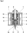
- FIG. 2 shows another advantageous embodiment for carrying out the method according to the invention.
- the furnace structure itself essentially corresponds to that of the embodiment shown in FIG. 1.
- 1 again denotes the susceptor
- 2 is the subsequent insulation in a concentric arrangement
- 3 is the surrounding quartz glass tube.
- the induction winding for heating the susceptor 1, which acts as a heating tube, is again designated 4
- 5 is the concentric one Outer wall
- 6 the base plate and 7 the furnace cover of the drawing furnace further developed according to the invention.
- a preform 9 is again introduced into the furnace chamber 8 from above, and the fiber 11 is drawn from the onion 10 after the glass material of the preform 9 has been brought into the molten state.
- an additional purge gas 16 is introduced from below against the direction of flow of this gas, which is caused by the reduction in cross-section of the preform Furnace space fulfilled and thus the entire purge gas flow stabilized at this point.
- a particularly expedient possibility for introducing the additional purge gas 16 is shown in the figure.
- an additional guide tube 17, for example made of graphite is introduced from below into the furnace chamber; its outer dimensions are sufficient for the drawing area, i. H. into the high temperature area of the furnace.
- the additional purge gas 16 is deflected at the upper end by the gas 14 coming from above and conducted downwards inside the guide tube 17, practically enveloping the fiber 11. Due to the additional amount of purge gas, the free cross section in the furnace area, which is enlarged in the drawing area, is filled with the purge gas, and the occurrence of turbulence is avoided.
- the invention is not limited to the exemplary embodiments shown, insofar as a specific embodiment of the furnace is specified here. Thus, the invention is applicable to any drawing yards for the given purpose, in which protective or purge gases are passed through the furnace interior.
Landscapes
- Engineering & Computer Science (AREA)
- Chemical & Material Sciences (AREA)
- Life Sciences & Earth Sciences (AREA)
- General Life Sciences & Earth Sciences (AREA)
- Geochemistry & Mineralogy (AREA)
- Manufacturing & Machinery (AREA)
- Materials Engineering (AREA)
- Organic Chemistry (AREA)
- Manufacture, Treatment Of Glass Fibers (AREA)
Applications Claiming Priority (2)
| Application Number | Priority Date | Filing Date | Title |
|---|---|---|---|
| DE4339077A DE4339077C2 (de) | 1993-11-16 | 1993-11-16 | Verfahren zum Ziehen einer optischen Faser und Vorrichtung zu dessen Durchführung |
| DE4339077 | 1993-11-16 |
Publications (2)
| Publication Number | Publication Date |
|---|---|
| EP0653383A1 true EP0653383A1 (fr) | 1995-05-17 |
| EP0653383B1 EP0653383B1 (fr) | 1998-05-20 |
Family
ID=6502704
Family Applications (1)
| Application Number | Title | Priority Date | Filing Date |
|---|---|---|---|
| EP94116152A Expired - Lifetime EP0653383B1 (fr) | 1993-11-16 | 1994-10-13 | Procédé et dispositif d'étirage d'une fibre optique |
Country Status (6)
| Country | Link |
|---|---|
| US (1) | US5545246A (fr) |
| EP (1) | EP0653383B1 (fr) |
| CA (1) | CA2135834A1 (fr) |
| DE (2) | DE4339077C2 (fr) |
| DK (1) | DK0653383T3 (fr) |
| FI (1) | FI945372L (fr) |
Cited By (3)
| Publication number | Priority date | Publication date | Assignee | Title |
|---|---|---|---|---|
| EP0849232A1 (fr) * | 1996-12-17 | 1998-06-24 | Alcatel | Procédé et appareil de l'étirage d'une fibre optique à partir d'une préforme |
| EP0867414A1 (fr) * | 1997-03-27 | 1998-09-30 | Alcatel | Elément de chauffage et tube en graphite imprégnés par du carbone vitreux pour un four d'étirage de fibres optiques |
| WO1999065834A1 (fr) * | 1998-06-13 | 1999-12-23 | Alcatel | Procede et dispositif pour etirer une fibre optique a partir d'une ebauche |
Families Citing this family (13)
| Publication number | Priority date | Publication date | Assignee | Title |
|---|---|---|---|---|
| JP3159116B2 (ja) * | 1997-04-11 | 2001-04-23 | 住友電気工業株式会社 | ガラス母材の延伸機および延伸方法 |
| DE19900375A1 (de) | 1999-01-08 | 2000-07-13 | Alcatel Sa | Vorrichtung zum Ziehen einer Faser |
| US6354113B2 (en) | 1999-01-20 | 2002-03-12 | Alcatel | Fiber optic draw furnace featuring a fiber optic preform heating and fiber drawing programmable logic controller |
| AU5211900A (en) * | 1999-05-10 | 2000-11-21 | Pirelli Cavi E Sistemi S.P.A. | Method and induction furnace for drawing large diameter preforms to optical fibres |
| EP1243568B1 (fr) * | 1999-05-27 | 2013-03-06 | Sumitomo Electric Industries, Ltd. | Procede de production pour fibre optique |
| JP4356155B2 (ja) * | 1999-10-12 | 2009-11-04 | 住友電気工業株式会社 | 光ファイバの製造方法 |
| EP1263687A4 (fr) * | 2000-03-10 | 2009-11-11 | Flow Focusing Inc | Procedes de production de fibres optiques par focalisation de liquide a viscosite elevee |
| US20020178762A1 (en) * | 2001-06-01 | 2002-12-05 | Foster John D. | Methods and apparatus for forming and controlling the diameter of drawn optical glass fiber |
| KR100545814B1 (ko) * | 2002-08-31 | 2006-01-24 | 엘에스전선 주식회사 | 광섬유 인선 용해로 및 이를 이용한 광섬유 인선방법 |
| JPWO2005049516A1 (ja) * | 2003-11-18 | 2007-06-07 | 株式会社フジクラ | 光ファイバ裸線の線引方法、光ファイバ素線の製造方法、光ファイバ素線 |
| WO2013105302A1 (fr) * | 2012-01-10 | 2013-07-18 | 住友電気工業株式会社 | Procédé de production et dispositif de production de fibre optique et fibre optique |
| US10308544B2 (en) * | 2015-10-13 | 2019-06-04 | Corning Incorporated | Gas reclamation system for optical fiber production |
| US20260035285A1 (en) * | 2024-07-31 | 2026-02-05 | Corning Incorporated | Furnace design to improve drawing of hollow-core fibers |
Citations (2)
| Publication number | Priority date | Publication date | Assignee | Title |
|---|---|---|---|---|
| US4673427A (en) * | 1982-10-04 | 1987-06-16 | U.S. Philips Corporation | Method of and device for drawing an optical fiber from a solid preform consisting substantially of SiO2 and doped SiO2 |
| EP0386756A1 (fr) * | 1989-03-08 | 1990-09-12 | Sumitomo Electric Industries, Ltd. | Four et procédé pour l'étirage de fibres optiques |
Family Cites Families (28)
| Publication number | Priority date | Publication date | Assignee | Title |
|---|---|---|---|---|
| USRE28029E (en) * | 1972-01-03 | 1974-06-04 | Method of forming optical waveguide fibers | |
| GB1507144A (en) * | 1974-07-10 | 1978-04-12 | Post Office | Apparatus for drawing dielectric optical waveguides |
| US4101300A (en) * | 1975-11-27 | 1978-07-18 | Hitachi, Ltd. | Method and apparatus for drawing optical fiber |
| US4030901A (en) * | 1976-07-19 | 1977-06-21 | Bell Telephone Laboratories, Incorporated | Method for drawing fibers |
| US4249925A (en) * | 1978-05-12 | 1981-02-10 | Fujitsu Limited | Method of manufacturing an optical fiber |
| FR2515693B1 (fr) * | 1981-11-03 | 1985-10-11 | Thomson Csf | Procede de fabrication d'un objet a structure chiralique issu a partir d'une source de matiere formable et dispositif mettant en oeuvre ce procede |
| CA1213441A (fr) * | 1981-11-05 | 1986-11-04 | Charles M. Darcangelo | Dispositif de refroidissement de fibres de guide de lumiere |
| US4514205A (en) * | 1981-11-05 | 1985-04-30 | Corning Glass Works | Fiber cooling apparatus |
| US4437870A (en) * | 1981-11-05 | 1984-03-20 | Corning Glass Works | Optical waveguide fiber cooler |
| US4396409A (en) * | 1981-12-11 | 1983-08-02 | Corning Glass Works | Method of improving fatigue resistance of optical fibers |
| US4440556A (en) * | 1982-06-23 | 1984-04-03 | International Telephone And Telegraph Corporation | Optical fiber drawing using plasma torch |
| GB2159812B (en) * | 1984-06-01 | 1988-02-10 | Stc Plc | Manufacturing optical fibre |
| NL8402799A (nl) * | 1984-09-13 | 1986-04-01 | Philips Nv | Werkwijze en inrichting voor het vervaardigen van een optische vezel met een kunststofbekleding. |
| US4531959A (en) * | 1984-10-04 | 1985-07-30 | Corning Glass Works | Method and apparatus for coating optical fibers |
| IT1184909B (it) * | 1985-03-18 | 1987-10-28 | Cselt Centro Studi Lab Telecom | Procedimento ed apparecchiatura per la riduzione dei difetti di volume e di superficie nelle fibre ottiche in silice |
| US4664689A (en) * | 1986-02-27 | 1987-05-12 | Union Carbide Corporation | Method and apparatus for rapidly cooling optical fiber |
| US4761168A (en) * | 1986-09-22 | 1988-08-02 | American Telephone And Telegraph Company, At&T Bell Laboratories | Optical fiber manufacturing technique |
| JP2808596B2 (ja) * | 1987-09-01 | 1998-10-08 | 住友電気工業株式会社 | 光ファイバ線引き炉 |
| FI78893C (fi) * | 1987-09-08 | 1989-10-10 | Nokia Oy Ab | Foerfarande och anordning foer kylning av en optisk fiber. |
| GB2212151B (en) * | 1987-11-12 | 1991-07-17 | Stc Plc | Contaminant removal in manufacture of optical fibre |
| JP2584808B2 (ja) * | 1987-12-28 | 1997-02-26 | 松下電器産業株式会社 | 時分割多重方式による光空間伝送装置 |
| AU605656B2 (en) * | 1988-02-24 | 1991-01-17 | Sumitomo Electric Industries, Ltd. | Fiber drawing furnace |
| JP2787983B2 (ja) * | 1988-04-25 | 1998-08-20 | 住友電気工業株式会社 | 光ファイバ線引き炉及び線引き方法 |
| DE4022131A1 (de) * | 1990-07-11 | 1992-01-16 | Kabelmetal Electro Gmbh | Verfahren und vorrichtung zum ziehen einer optischen faser aus einer festen vorform |
| JP2798486B2 (ja) * | 1990-08-01 | 1998-09-17 | 住友電気工業株式会社 | ハーメチックコート光ファイバの製造方法及び製造装置 |
| US5059229A (en) * | 1990-09-24 | 1991-10-22 | Corning Incorporated | Method for producing optical fiber in a hydrogen atmosphere to prevent attenuation |
| JPH05208840A (ja) * | 1991-12-24 | 1993-08-20 | Fujikura Ltd | 光ファイバ紡糸方法および光ファイバ紡糸装置 |
| US5284499A (en) * | 1992-05-01 | 1994-02-08 | Corning Incorporated | Method and apparatus for drawing optical fibers |
-
1993
- 1993-11-16 DE DE4339077A patent/DE4339077C2/de not_active Expired - Fee Related
-
1994
- 1994-10-13 DK DK94116152T patent/DK0653383T3/da active
- 1994-10-13 EP EP94116152A patent/EP0653383B1/fr not_active Expired - Lifetime
- 1994-10-13 DE DE59406011T patent/DE59406011D1/de not_active Expired - Lifetime
- 1994-11-08 US US08/336,190 patent/US5545246A/en not_active Expired - Lifetime
- 1994-11-15 CA CA002135834A patent/CA2135834A1/fr not_active Abandoned
- 1994-11-15 FI FI945372A patent/FI945372L/fi unknown
Patent Citations (2)
| Publication number | Priority date | Publication date | Assignee | Title |
|---|---|---|---|---|
| US4673427A (en) * | 1982-10-04 | 1987-06-16 | U.S. Philips Corporation | Method of and device for drawing an optical fiber from a solid preform consisting substantially of SiO2 and doped SiO2 |
| EP0386756A1 (fr) * | 1989-03-08 | 1990-09-12 | Sumitomo Electric Industries, Ltd. | Four et procédé pour l'étirage de fibres optiques |
Cited By (4)
| Publication number | Priority date | Publication date | Assignee | Title |
|---|---|---|---|---|
| EP0849232A1 (fr) * | 1996-12-17 | 1998-06-24 | Alcatel | Procédé et appareil de l'étirage d'une fibre optique à partir d'une préforme |
| EP0867414A1 (fr) * | 1997-03-27 | 1998-09-30 | Alcatel | Elément de chauffage et tube en graphite imprégnés par du carbone vitreux pour un four d'étirage de fibres optiques |
| US6044663A (en) * | 1997-03-27 | 2000-04-04 | Alcatel | Impregnated vitreous (glassy) carbon graphite liner and heating element for a fiber optic draw furnace |
| WO1999065834A1 (fr) * | 1998-06-13 | 1999-12-23 | Alcatel | Procede et dispositif pour etirer une fibre optique a partir d'une ebauche |
Also Published As
| Publication number | Publication date |
|---|---|
| FI945372A0 (fi) | 1994-11-15 |
| CA2135834A1 (fr) | 1995-05-17 |
| US5545246A (en) | 1996-08-13 |
| DE59406011D1 (de) | 1998-06-25 |
| EP0653383B1 (fr) | 1998-05-20 |
| FI945372A7 (fi) | 1995-05-17 |
| DK0653383T3 (da) | 1999-03-08 |
| DE4339077C2 (de) | 1997-03-06 |
| DE4339077A1 (de) | 1995-05-18 |
| FI945372L (fi) | 1995-05-17 |
Similar Documents
| Publication | Publication Date | Title |
|---|---|---|
| DE4339077C2 (de) | Verfahren zum Ziehen einer optischen Faser und Vorrichtung zu dessen Durchführung | |
| EP0849232B1 (fr) | Procédé et appareil de l'étirage d'une fibre optique à partir d'une préforme | |
| DE69112513T2 (de) | Verfahren zum Ziehen optischer Fasern. | |
| DE2906070C2 (de) | Verfahren zum Herstellen von optischen Wellenleitern | |
| DE3234207C2 (fr) | ||
| DE69311841T2 (de) | Verfahren und Vorrichtung zum Ziehen von optischen Fasern | |
| EP0105563B2 (fr) | Appareil pour l'étirage d'une fibre optique à partir d'une préforme solide consistant de SiO2 et du SiO2 dopé | |
| DE69132840T2 (de) | Verfahren zur Herstellung einer polarisationserhaltenden Faser | |
| DE2850969C2 (fr) | ||
| EP0187405B1 (fr) | Procédé pour la fabrication de fibres optiques | |
| DE2906071A1 (de) | Verfahren zum ziehen von faeden aus thermoplastischem material | |
| DE3105295A1 (de) | Halbfabrikat fuer die herstellung von optischen fasern, verfahren zur herstellung des halbfabrikats und die aus dem halbfabrikat hergestellten optischen fasern | |
| DE2217725A1 (de) | Verfahren zur herstellung eines laenglichen quarzteils | |
| DE2919080A1 (de) | Verfahren zum herstellen einer optischen faser | |
| EP0755900A1 (fr) | Procédé et dispositif pour la fabrication de préformes en verre de silice par déposition en phase vapeur | |
| DE2524335C2 (fr) | ||
| DE3118351A1 (de) | "vorrichtung zum niederschlagen einer schicht aus glas auf einer inneren oberflaeche eines glas-fangrohres" | |
| CH660659A5 (de) | Verfahren zum erhitzen eines lichtleitfaser-rohlingteils und heizanordnung zur durchfuehrung des verfahrens. | |
| DE19716133A1 (de) | Vorrichtung zum Herstellen einer Lichtleitfaser und Verfahren dafür | |
| DE3304552A1 (de) | Verfahren zur herstellung von lichtwellenleitern | |
| DE4203369A1 (de) | Verfahren und vorrichtung zum herstellen von aussenbeschichteten glaskoerpern zur herstellung von lichtwellenleitern | |
| DE3008416A1 (de) | Verfahren zur herstellung eines glasfaser-lichtleiters | |
| DE60108782T2 (de) | Vorrichtung und verfahren zur herstellung einer vorform für eine lichtleitfaser | |
| DE2605483A1 (de) | Verfahren zur herstellung eines lichtleiters | |
| EP0132011B1 (fr) | Procédé de fabrication de guides de lumière en fibre |
Legal Events
| Date | Code | Title | Description |
|---|---|---|---|
| PUAI | Public reference made under article 153(3) epc to a published international application that has entered the european phase |
Free format text: ORIGINAL CODE: 0009012 |
|
| 17P | Request for examination filed |
Effective date: 19950201 |
|
| AK | Designated contracting states |
Kind code of ref document: A1 Designated state(s): DE DK FR GB IT NL SE |
|
| 17Q | First examination report despatched |
Effective date: 19961112 |
|
| GRAG | Despatch of communication of intention to grant |
Free format text: ORIGINAL CODE: EPIDOS AGRA |
|
| GRAG | Despatch of communication of intention to grant |
Free format text: ORIGINAL CODE: EPIDOS AGRA |
|
| GRAH | Despatch of communication of intention to grant a patent |
Free format text: ORIGINAL CODE: EPIDOS IGRA |
|
| GRAH | Despatch of communication of intention to grant a patent |
Free format text: ORIGINAL CODE: EPIDOS IGRA |
|
| RAP1 | Party data changed (applicant data changed or rights of an application transferred) |
Owner name: ALCATEL ALSTHOM COMPAGNIE GENERALE D'ELECTRICITE |
|
| GRAA | (expected) grant |
Free format text: ORIGINAL CODE: 0009210 |
|
| AK | Designated contracting states |
Kind code of ref document: B1 Designated state(s): DE DK FR GB IT NL SE |
|
| REF | Corresponds to: |
Ref document number: 59406011 Country of ref document: DE Date of ref document: 19980625 |
|
| ITF | It: translation for a ep patent filed | ||
| GBT | Gb: translation of ep patent filed (gb section 77(6)(a)/1977) |
Effective date: 19980713 |
|
| ET | Fr: translation filed | ||
| RAP4 | Party data changed (patent owner data changed or rights of a patent transferred) |
Owner name: ALCATEL |
|
| REG | Reference to a national code |
Ref country code: DK Ref legal event code: T3 |
|
| PLBE | No opposition filed within time limit |
Free format text: ORIGINAL CODE: 0009261 |
|
| STAA | Information on the status of an ep patent application or granted ep patent |
Free format text: STATUS: NO OPPOSITION FILED WITHIN TIME LIMIT |
|
| RAP4 | Party data changed (patent owner data changed or rights of a patent transferred) |
Owner name: ALCATEL |
|
| 26N | No opposition filed | ||
| REG | Reference to a national code |
Ref country code: FR Ref legal event code: CD |
|
| PGFP | Annual fee paid to national office [announced via postgrant information from national office to epo] |
Ref country code: NL Payment date: 20000925 Year of fee payment: 7 |
|
| PGFP | Annual fee paid to national office [announced via postgrant information from national office to epo] |
Ref country code: SE Payment date: 20001002 Year of fee payment: 7 Ref country code: DK Payment date: 20001002 Year of fee payment: 7 |
|
| PG25 | Lapsed in a contracting state [announced via postgrant information from national office to epo] |
Ref country code: DK Free format text: LAPSE BECAUSE OF NON-PAYMENT OF DUE FEES Effective date: 20011013 |
|
| PG25 | Lapsed in a contracting state [announced via postgrant information from national office to epo] |
Ref country code: SE Free format text: LAPSE BECAUSE OF NON-PAYMENT OF DUE FEES Effective date: 20011014 |
|
| REG | Reference to a national code |
Ref country code: GB Ref legal event code: IF02 |
|
| PG25 | Lapsed in a contracting state [announced via postgrant information from national office to epo] |
Ref country code: NL Free format text: LAPSE BECAUSE OF NON-PAYMENT OF DUE FEES Effective date: 20020501 |
|
| EUG | Se: european patent has lapsed |
Ref document number: 94116152.3 |
|
| REG | Reference to a national code |
Ref country code: DK Ref legal event code: EBP |
|
| NLV4 | Nl: lapsed or anulled due to non-payment of the annual fee |
Effective date: 20020501 |
|
| PGFP | Annual fee paid to national office [announced via postgrant information from national office to epo] |
Ref country code: DE Payment date: 20131021 Year of fee payment: 20 Ref country code: GB Payment date: 20131021 Year of fee payment: 20 Ref country code: FR Payment date: 20131022 Year of fee payment: 20 |
|
| PGFP | Annual fee paid to national office [announced via postgrant information from national office to epo] |
Ref country code: IT Payment date: 20131028 Year of fee payment: 20 |
|
| REG | Reference to a national code |
Ref country code: DE Ref legal event code: R071 Ref document number: 59406011 Country of ref document: DE |
|
| REG | Reference to a national code |
Ref country code: GB Ref legal event code: PE20 Expiry date: 20141012 |
|
| PG25 | Lapsed in a contracting state [announced via postgrant information from national office to epo] |
Ref country code: GB Free format text: LAPSE BECAUSE OF EXPIRATION OF PROTECTION Effective date: 20141012 |