EP0653564A1 - Verstopfungsfreie Kreiselpumpe - Google Patents
Verstopfungsfreie Kreiselpumpe Download PDFInfo
- Publication number
- EP0653564A1 EP0653564A1 EP94103553A EP94103553A EP0653564A1 EP 0653564 A1 EP0653564 A1 EP 0653564A1 EP 94103553 A EP94103553 A EP 94103553A EP 94103553 A EP94103553 A EP 94103553A EP 0653564 A1 EP0653564 A1 EP 0653564A1
- Authority
- EP
- European Patent Office
- Prior art keywords
- impeller
- centrifugal pump
- pump according
- collar
- forms
- Prior art date
- Legal status (The legal status is an assumption and is not a legal conclusion. Google has not performed a legal analysis and makes no representation as to the accuracy of the status listed.)
- Granted
Links
- 239000007787 solid Substances 0.000 claims description 12
- 239000002657 fibrous material Substances 0.000 claims description 3
- 230000000149 penetrating effect Effects 0.000 claims description 3
- 230000000694 effects Effects 0.000 description 2
- 239000007788 liquid Substances 0.000 description 2
- 239000002351 wastewater Substances 0.000 description 2
- 238000010276 construction Methods 0.000 description 1
- 238000004519 manufacturing process Methods 0.000 description 1
- 230000007704 transition Effects 0.000 description 1
Images


Classifications
-
- F—MECHANICAL ENGINEERING; LIGHTING; HEATING; WEAPONS; BLASTING
- F04—POSITIVE - DISPLACEMENT MACHINES FOR LIQUIDS; PUMPS FOR LIQUIDS OR ELASTIC FLUIDS
- F04D—NON-POSITIVE-DISPLACEMENT PUMPS
- F04D29/00—Details, component parts, or accessories
- F04D29/40—Casings; Connections of working fluid
- F04D29/42—Casings; Connections of working fluid for radial or helico-centrifugal pumps
- F04D29/426—Casings; Connections of working fluid for radial or helico-centrifugal pumps especially adapted for liquid pumps
- F04D29/4273—Casings; Connections of working fluid for radial or helico-centrifugal pumps especially adapted for liquid pumps suction eyes
-
- F—MECHANICAL ENGINEERING; LIGHTING; HEATING; WEAPONS; BLASTING
- F04—POSITIVE - DISPLACEMENT MACHINES FOR LIQUIDS; PUMPS FOR LIQUIDS OR ELASTIC FLUIDS
- F04D—NON-POSITIVE-DISPLACEMENT PUMPS
- F04D29/00—Details, component parts, or accessories
- F04D29/18—Rotors
- F04D29/22—Rotors specially for centrifugal pumps
- F04D29/2238—Special flow patterns
- F04D29/225—Channel wheels, e.g. one blade or one flow channel
-
- F—MECHANICAL ENGINEERING; LIGHTING; HEATING; WEAPONS; BLASTING
- F04—POSITIVE - DISPLACEMENT MACHINES FOR LIQUIDS; PUMPS FOR LIQUIDS OR ELASTIC FLUIDS
- F04D—NON-POSITIVE-DISPLACEMENT PUMPS
- F04D7/00—Pumps adapted for handling specific fluids, e.g. by selection of specific materials for pumps or pump parts
- F04D7/02—Pumps adapted for handling specific fluids, e.g. by selection of specific materials for pumps or pump parts of centrifugal type
- F04D7/04—Pumps adapted for handling specific fluids, e.g. by selection of specific materials for pumps or pump parts of centrifugal type the fluids being viscous or non-homogenous
- F04D7/045—Pumps adapted for handling specific fluids, e.g. by selection of specific materials for pumps or pump parts of centrifugal type the fluids being viscous or non-homogenous with means for comminuting, mixing stirring or otherwise treating
Definitions
- the invention relates to a centrifugal pump with a single-bladed impeller whose central suction mouth facing away from the drive shaft is aligned with the inlet opening of the pump chamber.
- Free-flow pumps are often used in wastewater loaded with solids. These free-flow pumps have efficiency maxima of approx. 50%, but the efficiency in practical use is below 40%. These low efficiencies result in overdimensioning of the drive motor. Since the motor in submersible pumps makes up around 80% of the value of a submersible pump, the investment costs required to pump a certain amount of liquid to a predetermined level increase.
- Free-flow pumps also have the peculiarity that solids accumulate in the middle of the impeller and reduce the free flow, so that the pump in throttled operation is running.
- the pump itself does not block because the impeller is far away from the wall of the pump housing.
- Impellers with better efficiency are single-channel impellers that have only one blade. These impellers achieve efficiencies of over 70% if they are spatially curved. The consequence of this spatial curvature is that the impellers cannot be turned off in order to reach other operating points. Therefore, you need a separate impeller and a separate model in the foundry for each characteristic. Cylindrical impellers can be turned and have a slightly lower efficiency than the spatially curved ones.
- the object of the invention is to improve a centrifugal pump of the type mentioned in such a way that, with simple construction and manufacture, it is to a large extent free of blockages.
- the inlet opening forms an annular collar which projects into the interior of the impeller in such a way that the inner end of the impeller blade forms a narrow gap with the outer jacket of the collar.
- Such a pump in particular does not become clogged by solids in the delivery medium, which are referred to as "pump fright", such as, for example, plastic bags and tights.
- the pump is therefore particularly suitable for wastewater of various types.
- the cylindrical impeller of the pump according to the invention can be turned off.
- a base plate is mounted, which forms the collar directly or through an insert.
- the insert forming the collar lines at least the area of the inlet that faces the impeller in a bush-like manner.
- the bottom of the chamber side wall facing the impeller in particular through a base plate, forms a spiral groove around the inlet, through which solids penetrating between the impeller and chamber side wall can be moved to the outside.
- Such a spiral entrains solids that squeeze between the lower edge of the impeller and the chamber side wall through the spiral and moves radially outward, so that the impeller automatically frees itself from trapped solids.
- a coaxial ring gear adjoins the outside of the collar on the base plate, the teeth of which are oriented approximately radially. These radial teeth ensure that the solid is not rotated endlessly with the impeller, but is held back so that the outwardly rotating spiral can develop its full effect. This also keeps solids that have wrapped around the front edge of the impeller from the teeth and also expose them to the action of the spiral. Finally, with certain solids, the teeth can have a grinding effect on the solids.
- the bottom plate facing end of the inner end of the impeller blade above the ring gear is a short distance.
- the spiral groove should adjoin the outside of the ring gear.
- the width of the teeth and thus the ring gear is approximately equal to the width of the end face of the inner end of the impeller blade, and the impeller blade end is provided with a radius, so that the fibrous materials can be drawn in much more easily.
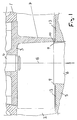
- a centrifugal pump has a pump housing 1, which forms a pump chamber 2, in which an impeller 3 is mounted.
- the impeller 3 is driven via a shaft 4 by an electric motor, not shown.
- the chamber 2 On the side facing away from the shaft 4 and the electric motor On the side, the chamber 2 is closed by a pump chamber side wall 5, which is perpendicular to the axis of the shaft 4 and forms a pump inlet 6, which is coaxial with the shaft 4 and is thus flush with the suction mouth of the impeller 3.
- the cylindrical and thus rotatable impeller 3 has only a single curved blade 7, the inside, i.e. the impeller axis 8 revolves near end 7a in close proximity to the edge of the inlet 6.
- the inner edge of the inlet 6 forms an annular collar 9 which extends a few millimeters into the impeller 3 and thus into the suction mouth of the impeller 3, so that the collar 9 projects a few millimeters beyond the inner end 7a.
- the collar 9 preferably covers the inner end 7a by 2 to 5, preferably by 2.5-3 millimeters.
- the collar 9 can be formed directly by the pump chamber side wall 5 (FIG. 1) or by a base plate 11 or an insert 12 fastened in the base plate 11 (FIG. 2).
- the insert 12 can line the inlet 6 in the form of a bush.
- the insert 6 is surrounded on the inside of the pump chamber side wall 5 by a spiral groove 13 which has a spiral direction A with respect to the circulating liquid such that solids penetrating between the impeller blade and chamber side wall are driven radially outwards, as is the case with the arrowed, dashed flow direction 14 in Figure 4 shows.
- a coaxially arranged toothed ring 15 is located between the collar 9 and the spiral groove 13, over which the end face 16 of the inner end of the impeller blade lies at a small distance, the width b of the toothed ring being approximately equal to the width B is the end face 16.
- the teeth of the ring gear 15 are approximately radial to the impeller axis 8, i.e. the (straight) tooth flank lines of the teeth are arranged approximately radially.
- the impeller blade front side has a radius at the lower end, which causes the fibrous materials to be drawn in by the impeller blade and forced to move outward through the base plate design.
- the transition from the inner end 7a to the end face 16 is therefore rounded, the rounding having the radius R.
Landscapes
- Engineering & Computer Science (AREA)
- Mechanical Engineering (AREA)
- General Engineering & Computer Science (AREA)
- Structures Of Non-Positive Displacement Pumps (AREA)
Abstract
Description
- Die Erfindung betrifft eine Kreiselpumpe mit einem einschaufligen Laufrad, dessen der Antriebswelle abgewandter mittiger Saugmund mit der Einlaßöffnung der Pumpenkammer fluchtet.
- In Abwässern, die mit Feststoffen beladen sind, werden häufig Freistrompumpen eingesetzt. Diese Freistrompumpen haben Wirkungsgradmaxima von ca. 50%, jedoch liegt der Wirkungsgrad im praktischen Anwendungsfall unter 40%. Diese niedrigen Wirkungsgrade haben eine Überdimensionierung des Antriebsmotors zur Folge. Da der Motor bei Tauchmotorpumpen rund 80% des Wertes einer Tauchmotorpumpe ausmacht, steigen die Investitionskosten, die benötigt werden, um eine bestimmte Flüssigkeitsmenge auf eine vorgegebene Höhe zu fördern.
- Freistrompumpen haben weiterhin die Eigenart, daß sich Feststoffe in der Mitte des Laufrades anlagern und den freien Durchfluß verkleinern, so daß die Pumpe im gedrosselten Betrieb läuft. Die Pumpe selbst blockiert nicht, da das Laufrad mit seiner Stirnseite weit von der Wandung des Pumpengehäuses entfernt ist.
- Laufräder mit besserem Wirkungsgrad sind Einkanallaufräder, die nur eine einzige Schaufel besitzen. Diese Laufräder erreichen Wirkungsgrade von über 70%, wenn sie räumlich gekrümmt sind. Diese räumliche Krümmung hat zur Folge, daß die Laufräder nicht abgedreht werden können, um andere Betriebspunkte zu erreichen. Daher benötigt man für jede Kennlinie ein separates Laufrad und ein eigenes Modell in der Gießerei. Zylindrische Laufräder sind abdrehbar und haben einen etwas geringeren Wirkungsgrad, als die räumlich gekrümmten.
- Aufgabe der Erfindung ist es, eine Kreiselpumpe der eingangs genannten Art so zu verbessern, daß sie bei einfacher Konstruktion und Herstellung in hohem Maße verstopfungsfrei ist.
- Diese Aufgabe wird erfindungsgemäß dadurch gelöst, daß die Einlaßöffnung einen ringförmigen Kragen bildet, der in das Laufradinnere derart vorspringt, daß das innere Ende der Laufradschaufel mit dem Außenmantel des Kragens einen engen Spalt bildet.
- Eine solche Pumpe verstopft insbesondere nicht durch Feststoffe im Fördermedium, die als "Pumpenschreck" bezeichnet werden, wie beispielsweise Plastiktüten und Strumpfhosen. Die Pumpe ist damit besonders tauglich für Abwässer verschiedener Art. Darüberhinaus ist das zylindrische Laufrad der erfindungsgemäßen Pumpe abdrehbar.
- Besonders vorteilhaft ist es, wenn in der Pumpenkammerseitenwand, die den Einlaß aufweist eine Bodenplatte gelagert ist, die den Kragen direkt oder durch einen Einsatz bildet.
- Hierbei wird vorzugsweise vorgeschlagen, daß der den Kragen bildende Einsatz buchsenförmig zumindest den Bereich des Einlasses auskleidet, der dem Laufrad zugewandt ist.
- Vorzugsweise wird vorgeschlagen, daß der dem Laufrad zugewandte Boden der Kammerseitenwand, insbesondere durch eine Bodenplatte, eine spiralförmige Nut um den Einlaß herum bildet, durch die zwischen Laufrad und Kammerseitenwand eindringende Feststoffe nach außen bewegbar sind. Durch eine solche Spirale werden Feststoffe, die sich zwischen der Unterkante des Laufrades und der Kammerseitenwand hindurchzwängen durch die Spirale mitgenommen und radial nach außen bewegt, so daß das Laufrad sich selbsttätig von eingeklemmten Feststoffen befreit.
- Von größtem Vorteil ist es, wenn an der Außenseite des Kragens auf der Bodenplatte ein koaxialer Zahnkranz angrenzt, dessen Zähne etwa radial ausgerichtet sind. Diese radialen Zähne bewirken, daß der Feststoff nicht mit dem Laufrad endlos herumgedreht, sondern zurückgehalten wird, so daß die nach außen drehende Spirale ihre volle Wirkung entfalten kann. Auch werden hierdurch Feststoffe, die sich um die Vorderkante des Laufrades geschlungen haben, von den Zähnen zurückgehalten und auch der Wirkung der Spirale ausgesetzt. Schließlich kann bei bestimmten Feststoffen von den Zähnen eine zerkleinernde Wirkung auf die Feststoffe ausgeübt werden.
- Vorzugsweise wird vorgeschlagen, daß die der Bodenplatte zugewandte Stirnseite des inneren Endes der Laufradschaufel über dem Zahnkranz mit geringem Abstand liegt. Hierbei sollte an der Außenseite des Zahnkranzes die Spiralnut angrenzen.
- Auch wird hierbei vorzugsweise vorgeschlagen, daß die Breite der Zähne und damit des Zahnkranzes etwa gleich der Breite der Stirnseite des inneren Endes der Laufradschaufel ist, sowie das Laufradschaufelende mit einem Radius versehen ist, so daß die Faserstoffe viel einfacher eingezogen werden können.
- Ausführungsbeispiele der Erfindung sind in den Zeichnungen dargestellt und werden im folgenden näher beschrieben. Es zeigen:
- Figur 1:
- Einen achsialen Schnitt durch ein erstes Ausführungsbeispiel im Ausschnitt.
- Figur 2:
- Einen achsialen Schnitt durch ein zweites Ausführungsbeispiel im Ausschnitt.
- Figur 3:
- Eine Ansicht der Pumpenkammerseitenwand mit Zahnkranz und einem inneren kurzen Bereich der Spirale und
- Firgur 4:
- eine perspektivische Ansicht von Kragen, Zahnkranz, Spirale und innerem Ende der Laufradschaufel in einem Ausschnitt.
- Eine Kreiselpumpe weist ein Pumpengehäuse 1 auf, das eine Pumpenkammer 2 bildet, in dem ein Laufrad 3 gelagert ist. Das Laufrad 3 wird über eine Welle 4 von einem nicht dargestellten Elektromotor angetrieben.
- Auf der der Welle 4 und dem Elektromotor abgewandten Seite ist die Kammer 2 durch eine Pumpenkammerseitenwand 5 verschlossen, die rechtwinklig zur Achse der Welle 4 liegt und einen Pumpeneinlaß 6 bildet, der koaxial zur Welle 4 liegt und damit mit dem Saugmund des Laufrades 3 fluchtet.
- Das zylindrische und damit abdrehbare Laufrad 3 weist nur eine einzige gekrümmte Schaufel 7 auf, deren Inneres, d.h. der Laufradachse 8 näheres Ende 7a in nächster Nähe des Randes des Einlasses 6 umläuft. Hierbei bildet der innere Rand des Einlasses 6 einen ringförmigen Kragen 9, der einige Millimeter in das Laufrad 3 und damit in den Saugmund des Laufrades 3 hineinreicht, so daß der Kragen 9 das innere Ende 7a um einige Millimeter überragt. Vorzugsweise überdeckt hierbei der Kragen 9 das innere Ende 7a um 2 bis 5, vorzugsweise um 2,5-3 Millimeter.
- Zwischen der Außenseite des Kragens 9 und der Innenwand des inneren Endes 7a der Laufradschaufel besteht ein Spalt 10 von nur etwa einem Bruchteil eines Millimeters, wobei die Breite S des Spaltes mit zunehmender Leistung wächst.
- Der Kragen 9 kann von der Pumpenkammerseitenwand 5 direkt gebildet sein (Figur 1) oder aber von einer Bodenplatte 11 oder einem in der Bodenplatte 11 befestigten Einsatz 12 (Figur 2). Hierbei kann der Einsatz 12 buchsenförmig den Einlaß 6 auskleiden.
- Wie Figur 1 zeigt, ist der Einsatz 6 an der Innenseite der Pumpenkammerseitenwand 5 von einer spiralförmigen Nut 13 umgeben, die bezüglich der kreisenden Flüssigkeit eine solche Spiralrichtung A hat, daß zwischen der Laufradschaufel und Kammerseitenwand eindringende Feststoffe radial nach außen getrieben werden, wie dies die mit Pfeilen versehene, gestrichelte Flußrichtung 14 in Figur 4 zeigt.
- Im Ausführungsbeispiel nach den Figuren 2 bis 4 befindet sich zwischen dem Kragen 9 und der spiralförmigen Nut 13 ein koaxial angeordneter Zahnkranz 15, über dem die Stirnseite 16 des inneren Endes der Laufradschaufel in geringem Abstand liegt, wobei die Breite b des Zahnkranzes etwa gleich der Breite B der Stirnseite 16 ist. Hierbei liegen die Zähne des Zahnkranzes 15 etwa radial zur Laufradachse 8, d.h. die (geraden) Zahnflankenlinien der Zähne sind etwa radial angeordnet.
- Besonders vorteilhaft ist es, wenn die Laufradschaufelvorderseite am unteren stirnseitigen Ende einen Radius erhält, der bewirkt, daß die Faserstoffe durch die Laufradschaufel eingezogen und gezwungen werden, sich durch die Bodenplattengestaltung nach außen zu bewegen. Der Übergang von dem inneren Ende 7a zur Stirnseite 16 ist also abgerundet, wobei die Abrundung den Radius R aufweist.
Claims (9)
- Kreiselpumpe mit einem einschaufligen Laufrad (3), dessen der Antriebswelle (4) abgewandter mittiger Saugmund mit der Einlaßöffnung (6) der Pumpenkammer (2) fluchtet, dadurch gekennzeichnet, daß die Einlaßöffnung (6) einen ringförmigen Kragen (9) bildet, der in das Laufradinnere derart vorspringt, daß das innere Ende (7a) der Laufradschaufel (7) mit dem Außenmantel des Kragens (9) einen engen Spalt (Breite S) bildet.
- Kreiselpumpe nach Anspruch 1, dadurch gekennzeichnet, daß in der Pumpenkammerseitenwand (5), die den Einlaß (6) aufweist, eine Bodenplatte (11) gelagert ist, die den Kragen (9) direkt oder durch einen Einsatz (12) bildet.
- Kreiselpumpe nach Anspruch 2, dadurch gekennzeichnet, daß der den Kragen (9) bildende Einsatz (12) buchsenförmig zumindest den Bereich des Einlasses (6) auskleidet, der dem Laufrad (3) zugewandt ist.
- Kreiselpumpe nach einem der vorherigen Ansprüche, dadurch gekennzeichnet, daß der dem Laufrad (3) zugewandte Boden der Kammerseitenwand (5), insbesondere durch eine Bodenplatte (11), eine spiralförmige Nut (13) um den Einlaß (6) herum bildet, durch die zwischen Laufrad (3) und Kammerseitenwand (5) eindringende Feststoffe nach außen bewegbar sind.
- Kreiselpumpe nach einem der vorherigen Ansprüche, dadurch gekennzeichnet, daß an der Außenseite des Kragens (9) auf der Bodenplatte (11) ein koaxialer Zahnkranz (15) angrenzt, dessen Zähne etwa radial ausgerichtet sind.
- Kreiselpumpe nach Anspruch 5, dadurch gekennzeichnet, daß die der Bodenplatte (11) zugewandte Stirnseite (16) des inneren Endes (7a) der Laufradschaufel (7) über dem Zahnkranz (15) mit geringem Abstand umläuft.
- Kreiselpumpe nach Anspruch 5 oder 6, dadurch gekennzeichnet, daß an der Außenseite des Zahnkranzes (15) die Spiralnut (13) angrenzt.
- Kreiselpumpe nach einem der Ansprüche 5 bis 7, dadurch gekennzeichnet, daß die Breite (b) der Zähne und damit des Zahnkranzes (15) etwa gleich der Breite (B) der Stirnseite (16) des inneren Endes (7a) der Laufradschaufel (7) ist.
- Kreiselpumpe nach einem der vorherigen Ansprüche, dadurch gekennzeichnet, daß das stirnseitige untere Ende der Laufradschaufelvorderseite eine Abrundung mit einem Radius (R) aufweist, durch den Faserstoffe eingezogen werden.
Applications Claiming Priority (2)
| Application Number | Priority Date | Filing Date | Title |
|---|---|---|---|
| DE4338931A DE4338931C2 (de) | 1993-11-15 | 1993-11-15 | Verstopfungsfreie Kreiselpumpe |
| DE4338931 | 1993-11-15 |
Publications (2)
| Publication Number | Publication Date |
|---|---|
| EP0653564A1 true EP0653564A1 (de) | 1995-05-17 |
| EP0653564B1 EP0653564B1 (de) | 1998-05-20 |
Family
ID=6502608
Family Applications (1)
| Application Number | Title | Priority Date | Filing Date |
|---|---|---|---|
| EP94103553A Expired - Lifetime EP0653564B1 (de) | 1993-11-15 | 1994-03-09 | Verstopfungsfreie Kreiselpumpe |
Country Status (4)
| Country | Link |
|---|---|
| US (1) | US5516261A (de) |
| EP (1) | EP0653564B1 (de) |
| AT (1) | ATE166433T1 (de) |
| DE (2) | DE4338931C2 (de) |
Families Citing this family (11)
| Publication number | Priority date | Publication date | Assignee | Title |
|---|---|---|---|---|
| US6921242B2 (en) * | 2001-07-10 | 2005-07-26 | Urs Blattmann | Centrifugal slurry pump |
| DE20114891U1 (de) * | 2001-09-10 | 2001-11-15 | Grundfos A/S, Bjerringbro | Abwasserkreiselpumpe |
| SE0302752L (sv) * | 2003-10-20 | 2005-02-15 | Itt Mfg Enterprises Inc | Centrifugalpump |
| US7037069B2 (en) * | 2003-10-31 | 2006-05-02 | The Gorman-Rupp Co. | Impeller and wear plate |
| SE0400964L (sv) * | 2004-04-15 | 2005-10-11 | Pumpex Ab | Kanalhjul |
| SE0501382L (sv) * | 2005-06-17 | 2006-06-13 | Itt Mfg Enterprises Inc | Pump för pumpning av förorenad vätska |
| CA2696883A1 (en) * | 2007-09-04 | 2009-03-12 | Envirotech Pumpsystems, Inc. | Wear plate with cutting elements for a centrifugal pump |
| DE102008016476A1 (de) * | 2008-03-31 | 2009-10-01 | BSH Bosch und Siemens Hausgeräte GmbH | Hausgerät mit einer Pumpe zur Förderung eines Mediums |
| US8118244B2 (en) * | 2010-03-11 | 2012-02-21 | Vaughan Company, Inc. | Internal cutter on submersed mixer |
| AU2011281111B2 (en) | 2010-07-21 | 2015-03-26 | Itt Manufacturing Enterprises Llc | Wear reduction device for rotary solids handling equipment |
| PE20211153A1 (es) | 2017-10-12 | 2021-06-28 | Weir Minerals Australia Ltd | Componente de entrada para una bomba de lechada |
Citations (5)
| Publication number | Priority date | Publication date | Assignee | Title |
|---|---|---|---|---|
| US1718396A (en) * | 1924-01-12 | 1929-06-25 | Raymond Guy Palmer | Centrifugal pump |
| US2245035A (en) * | 1939-02-13 | 1941-06-10 | American Well Works | Centrifugal sludge pump |
| US2265758A (en) * | 1940-05-29 | 1941-12-09 | Buffalo Pumps Inc | Pump |
| US3447475A (en) * | 1967-01-09 | 1969-06-03 | Albert Blum | Centrifugal pump |
| EP0395604A1 (de) * | 1989-04-27 | 1990-10-31 | ITT Flygt Aktiebolag | Kreiselpumpe |
Family Cites Families (16)
| Publication number | Priority date | Publication date | Assignee | Title |
|---|---|---|---|---|
| DE1990672U (de) * | 1968-08-01 | Blum, Albert, 5201 Scheiderhöhe/DE | Schmutzwasserpumpe | |
| DE240859C (de) * | 1911-04-14 | 1911-11-18 | Kreiselpumpe für fördergut mit festen bestandteilen | |
| DE614426C (de) * | 1933-09-21 | 1935-06-07 | A D Sihl A G Vorm A Schmid Mas | Kreiselpumpe fuer verunreinigte Fluessigkeiten |
| US3020850A (en) * | 1958-02-27 | 1962-02-13 | Meckum Engineering Inc | Dredge pump seal |
| AT211773B (de) * | 1958-07-15 | 1960-11-10 | Tornado A G | Elektrischer Staubsauger |
| DE1137629B (de) * | 1959-04-02 | 1962-10-04 | Georg Volland Dr Ing | Einkanalrad-Kreiselpumpe, insbesondere zur Foerderung von Abwaessern |
| US3096718A (en) * | 1961-12-12 | 1963-07-09 | Conard Kenner | Trash cutter for a pump |
| AT255912B (de) * | 1964-07-01 | 1967-07-25 | Schlesiger & Co Kg Feluwa | Schmutzwasser-Kreiselpumpe |
| CH411584A (de) * | 1964-07-10 | 1966-04-15 | Kolb Eugen Ag | Zentrifugalpumpe zum Fördern von verunreinigten Flüssigkeiten |
| DE6921357U (de) * | 1969-05-22 | 1969-10-09 | Hans Hoffmann Elmasch Bau Fa | Abwasserpumpe |
| FI49345C (fi) * | 1972-05-15 | 1975-05-12 | Ahlstroem Oy | Laite tiivistysraon tukkeutumisen estämiseksi etenkin jätevesipumpussa tai sentapaisessa. |
| DE2344576A1 (de) * | 1973-09-04 | 1975-03-13 | Neratoom | Kreiselpumpe zum verarbeiten von schleifende bestandteile enthaltenden fluessigkeiten, insbesondere eine sandpumpe oder schmutzwasserpumpe |
| FI750217A7 (de) * | 1975-01-28 | 1976-07-30 | Sarlin Ab Oy E | |
| DE2612910A1 (de) * | 1976-03-26 | 1977-09-29 | Albert Blum | Abwasserpumpe |
| SU798359A1 (ru) * | 1978-12-08 | 1981-01-23 | Латвийский Научно-Исследовательскийинститут Механизации И Электрифика-Ции Сельского Хозяйства | Центробежный насос дл перекачи-ВАНи НЕОдНОРОдНыХ СРЕд C ВОлОК-НиСТыМи ВКлючЕНи Ми |
| DE3015755A1 (de) * | 1980-04-24 | 1981-11-05 | Albert 5204 Lohmar Blum | Abwasserpumpe, insbesondere tauchpumpe |
-
1993
- 1993-11-15 DE DE4338931A patent/DE4338931C2/de not_active Expired - Fee Related
-
1994
- 1994-03-09 AT AT94103553T patent/ATE166433T1/de not_active IP Right Cessation
- 1994-03-09 DE DE59406012T patent/DE59406012D1/de not_active Expired - Lifetime
- 1994-03-09 EP EP94103553A patent/EP0653564B1/de not_active Expired - Lifetime
- 1994-06-10 US US08/258,241 patent/US5516261A/en not_active Expired - Lifetime
Patent Citations (5)
| Publication number | Priority date | Publication date | Assignee | Title |
|---|---|---|---|---|
| US1718396A (en) * | 1924-01-12 | 1929-06-25 | Raymond Guy Palmer | Centrifugal pump |
| US2245035A (en) * | 1939-02-13 | 1941-06-10 | American Well Works | Centrifugal sludge pump |
| US2265758A (en) * | 1940-05-29 | 1941-12-09 | Buffalo Pumps Inc | Pump |
| US3447475A (en) * | 1967-01-09 | 1969-06-03 | Albert Blum | Centrifugal pump |
| EP0395604A1 (de) * | 1989-04-27 | 1990-10-31 | ITT Flygt Aktiebolag | Kreiselpumpe |
Also Published As
| Publication number | Publication date |
|---|---|
| DE4338931C2 (de) | 1996-09-05 |
| US5516261A (en) | 1996-05-14 |
| DE59406012D1 (de) | 1998-06-25 |
| EP0653564B1 (de) | 1998-05-20 |
| DE4338931A1 (de) | 1995-05-18 |
| ATE166433T1 (de) | 1998-06-15 |
Similar Documents
| Publication | Publication Date | Title |
|---|---|---|
| DE69332086T2 (de) | Pumpenlaufrad und kreiselpumpe für zähflussige medien mit diesem laufrad | |
| DE69620635T2 (de) | Pumpenlaufrad mit getrennten, versetzten leitschaufeln | |
| DE19518101C2 (de) | Seitenkanalpumpe | |
| DE69023699T2 (de) | Selbstansaugende Kreiselpumpe. | |
| DE69015874T2 (de) | Rotationshydraulikpumpe. | |
| DE69104455T2 (de) | Regenerativkreiselverdichter. | |
| EP0653564A1 (de) | Verstopfungsfreie Kreiselpumpe | |
| DE1453782A1 (de) | Zentrifugalpumpe | |
| DE4209126C2 (de) | Peripheralpumpe | |
| DE2405655A1 (de) | Pitot-kreiselpumpe mit geschlitzten einlasskanaelen im rotorgehaeuse | |
| DE69307835T2 (de) | Pumpengehäuse Vorrichtung | |
| DE4039712C2 (de) | Peripheralpumpe | |
| EP0443354B1 (de) | Kreiselpumpe | |
| DE69119765T2 (de) | Pumpe mit spiralförmigen schaufeln | |
| DE69414344T2 (de) | Seitenströmungspumpe | |
| DE102008056106B4 (de) | Seitenkanalgebläse, insbesondere Sekundärluftgebläse für eine Verbrennungskraftmaschine | |
| DE60217638T2 (de) | Kreiselpumpenlaufrad | |
| DE4239071C2 (de) | Tauchpumpenaggregat | |
| DE1528682B2 (de) | Kreiselpumpenbausatz | |
| EP0017829B1 (de) | Kreiselpumpe und ihr Gehäuse | |
| EP3728859A1 (de) | Seitenkanalgebläse, insbesondere sekundärluftgebläse für eine verbrennungskraftmaschine | |
| DE2422364A1 (de) | Einrichtung bei kreiselpumpen | |
| EP2342465B1 (de) | Seitenkanalgebläse, insbesondere sekundärluftgebläse für eine verbrennungskraftmaschine | |
| DE69903904T2 (de) | Waagerechte selbstansaugende Pumpe mit axialem Einlass | |
| DE3211230A1 (de) | Kreiselpumpe, insbesondere fuer schmutz- und abwasser |
Legal Events
| Date | Code | Title | Description |
|---|---|---|---|
| PUAI | Public reference made under article 153(3) epc to a published international application that has entered the european phase |
Free format text: ORIGINAL CODE: 0009012 |
|
| AK | Designated contracting states |
Kind code of ref document: A1 Designated state(s): AT CH DE ES FR GB IT LI NL SE |
|
| 17P | Request for examination filed |
Effective date: 19950701 |
|
| 17Q | First examination report despatched |
Effective date: 19961120 |
|
| GRAG | Despatch of communication of intention to grant |
Free format text: ORIGINAL CODE: EPIDOS AGRA |
|
| GRAG | Despatch of communication of intention to grant |
Free format text: ORIGINAL CODE: EPIDOS AGRA |
|
| GRAH | Despatch of communication of intention to grant a patent |
Free format text: ORIGINAL CODE: EPIDOS IGRA |
|
| GRAH | Despatch of communication of intention to grant a patent |
Free format text: ORIGINAL CODE: EPIDOS IGRA |
|
| GRAA | (expected) grant |
Free format text: ORIGINAL CODE: 0009210 |
|
| AK | Designated contracting states |
Kind code of ref document: B1 Designated state(s): AT CH DE ES FR GB IT LI NL SE |
|
| PG25 | Lapsed in a contracting state [announced via postgrant information from national office to epo] |
Ref country code: ES Free format text: THE PATENT HAS BEEN ANNULLED BY A DECISION OF A NATIONAL AUTHORITY Effective date: 19980520 |
|
| REF | Corresponds to: |
Ref document number: 166433 Country of ref document: AT Date of ref document: 19980615 Kind code of ref document: T |
|
| REG | Reference to a national code |
Ref country code: CH Ref legal event code: EP |
|
| ET | Fr: translation filed | ||
| GBT | Gb: translation of ep patent filed (gb section 77(6)(a)/1977) |
Effective date: 19980520 |
|
| REF | Corresponds to: |
Ref document number: 59406012 Country of ref document: DE Date of ref document: 19980625 |
|
| ITF | It: translation for a ep patent filed | ||
| PG25 | Lapsed in a contracting state [announced via postgrant information from national office to epo] |
Ref country code: SE Free format text: LAPSE BECAUSE OF FAILURE TO SUBMIT A TRANSLATION OF THE DESCRIPTION OR TO PAY THE FEE WITHIN THE PRESCRIBED TIME-LIMIT Effective date: 19980820 |
|
| PG25 | Lapsed in a contracting state [announced via postgrant information from national office to epo] |
Ref country code: AT Free format text: LAPSE BECAUSE OF NON-PAYMENT OF DUE FEES Effective date: 19990309 |
|
| PLBE | No opposition filed within time limit |
Free format text: ORIGINAL CODE: 0009261 |
|
| STAA | Information on the status of an ep patent application or granted ep patent |
Free format text: STATUS: NO OPPOSITION FILED WITHIN TIME LIMIT |
|
| PG25 | Lapsed in a contracting state [announced via postgrant information from national office to epo] |
Ref country code: LI Free format text: LAPSE BECAUSE OF NON-PAYMENT OF DUE FEES Effective date: 19990331 Ref country code: CH Free format text: LAPSE BECAUSE OF NON-PAYMENT OF DUE FEES Effective date: 19990331 |
|
| 26N | No opposition filed | ||
| REG | Reference to a national code |
Ref country code: CH Ref legal event code: PL |
|
| REG | Reference to a national code |
Ref country code: GB Ref legal event code: IF02 |
|
| PG25 | Lapsed in a contracting state [announced via postgrant information from national office to epo] |
Ref country code: IT Free format text: LAPSE BECAUSE OF NON-PAYMENT OF DUE FEES;WARNING: LAPSES OF ITALIAN PATENTS WITH EFFECTIVE DATE BEFORE 2007 MAY HAVE OCCURRED AT ANY TIME BEFORE 2007. THE CORRECT EFFECTIVE DATE MAY BE DIFFERENT FROM THE ONE RECORDED. Effective date: 20050309 |
|
| NLT1 | Nl: modifications of names registered in virtue of documents presented to the patent office pursuant to art. 16 a, paragraph 1 |
Owner name: WILO AG |
|
| PGRI | Patent reinstated in contracting state [announced from national office to epo] |
Ref country code: IT Effective date: 20080301 |
|
| PGFP | Annual fee paid to national office [announced via postgrant information from national office to epo] |
Ref country code: NL Payment date: 20090303 Year of fee payment: 16 |
|
| PGFP | Annual fee paid to national office [announced via postgrant information from national office to epo] |
Ref country code: GB Payment date: 20090304 Year of fee payment: 16 |
|
| PGFP | Annual fee paid to national office [announced via postgrant information from national office to epo] |
Ref country code: IT Payment date: 20100316 Year of fee payment: 17 |
|
| REG | Reference to a national code |
Ref country code: NL Ref legal event code: V1 Effective date: 20101001 |
|
| GBPC | Gb: european patent ceased through non-payment of renewal fee |
Effective date: 20100309 |
|
| PG25 | Lapsed in a contracting state [announced via postgrant information from national office to epo] |
Ref country code: NL Free format text: LAPSE BECAUSE OF NON-PAYMENT OF DUE FEES Effective date: 20101001 |
|
| PG25 | Lapsed in a contracting state [announced via postgrant information from national office to epo] |
Ref country code: GB Free format text: LAPSE BECAUSE OF NON-PAYMENT OF DUE FEES Effective date: 20100309 |
|
| PG25 | Lapsed in a contracting state [announced via postgrant information from national office to epo] |
Ref country code: IT Free format text: LAPSE BECAUSE OF NON-PAYMENT OF DUE FEES Effective date: 20110309 |
|
| PGFP | Annual fee paid to national office [announced via postgrant information from national office to epo] |
Ref country code: FR Payment date: 20120319 Year of fee payment: 19 |
|
| PGFP | Annual fee paid to national office [announced via postgrant information from national office to epo] |
Ref country code: DE Payment date: 20120411 Year of fee payment: 19 |
|
| REG | Reference to a national code |
Ref country code: FR Ref legal event code: ST Effective date: 20131129 |
|
| REG | Reference to a national code |
Ref country code: DE Ref legal event code: R119 Ref document number: 59406012 Country of ref document: DE Effective date: 20131001 |
|
| PG25 | Lapsed in a contracting state [announced via postgrant information from national office to epo] |
Ref country code: FR Free format text: LAPSE BECAUSE OF NON-PAYMENT OF DUE FEES Effective date: 20130402 Ref country code: DE Free format text: LAPSE BECAUSE OF NON-PAYMENT OF DUE FEES Effective date: 20131001 |