EP0653566A1 - Compresseur et transmission pour le compression d'oxygène - Google Patents
Compresseur et transmission pour le compression d'oxygène Download PDFInfo
- Publication number
- EP0653566A1 EP0653566A1 EP94112720A EP94112720A EP0653566A1 EP 0653566 A1 EP0653566 A1 EP 0653566A1 EP 94112720 A EP94112720 A EP 94112720A EP 94112720 A EP94112720 A EP 94112720A EP 0653566 A1 EP0653566 A1 EP 0653566A1
- Authority
- EP
- European Patent Office
- Prior art keywords
- compressor
- bearing
- gear
- oxygen
- bearings
- Prior art date
- Legal status (The legal status is an assumption and is not a legal conclusion. Google has not performed a legal analysis and makes no representation as to the accuracy of the status listed.)
- Granted
Links
Images


Classifications
-
- F—MECHANICAL ENGINEERING; LIGHTING; HEATING; WEAPONS; BLASTING
- F04—POSITIVE - DISPLACEMENT MACHINES FOR LIQUIDS; PUMPS FOR LIQUIDS OR ELASTIC FLUIDS
- F04D—NON-POSITIVE-DISPLACEMENT PUMPS
- F04D29/00—Details, component parts, or accessories
- F04D29/05—Shafts or bearings, or assemblies thereof, specially adapted for elastic fluid pumps
- F04D29/056—Bearings
-
- F—MECHANICAL ENGINEERING; LIGHTING; HEATING; WEAPONS; BLASTING
- F04—POSITIVE - DISPLACEMENT MACHINES FOR LIQUIDS; PUMPS FOR LIQUIDS OR ELASTIC FLUIDS
- F04D—NON-POSITIVE-DISPLACEMENT PUMPS
- F04D25/00—Pumping installations or systems
- F04D25/02—Units comprising pumps and their driving means
-
- F—MECHANICAL ENGINEERING; LIGHTING; HEATING; WEAPONS; BLASTING
- F04—POSITIVE - DISPLACEMENT MACHINES FOR LIQUIDS; PUMPS FOR LIQUIDS OR ELASTIC FLUIDS
- F04D—NON-POSITIVE-DISPLACEMENT PUMPS
- F04D25/00—Pumping installations or systems
- F04D25/16—Combinations of two or more pumps ; Producing two or more separate gas flows
- F04D25/163—Combinations of two or more pumps ; Producing two or more separate gas flows driven by a common gearing arrangement
Definitions
- the invention relates to a gear compressor for the compression of oxygen according to the preamble of claim 1.
- oxygen has mainly been compressed using so-called classic, multi-stage single-shaft compressors and, depending on the final pressure, multi-housing compressors of this type.
- Oxygen can also be compressed by geared compressors if the following design features are observed.
- the lubricating oil for the bearings and the pumped medium oxygen must be carefully separated from one another due to the risk of explosion. Therefore, in such compressors, the sealing systems (labyrinths) between the bearings and the impellers are greatly extended and designed as multi-chamber systems. As a result, however, the overhang between the center of gravity of the impeller and the center of the bearing becomes disproportionately large, which inevitably leads to unfavorable rotor dynamic properties.
- the object of the invention is to keep the compressed oxygen and the lubricating oil separate from one another in the compression of oxygen in a gearbox compressor and at the same time to achieve favorable rotor-dynamic properties for the gearbox compressor.
- a space is created between the gear housing carrying the lubricating oil and the oxygen-promoting compressor stages which is open to the ambient air.
- This space allows oxygen and lubricating oil to be separated from one another. Oxygen possibly escaping from the shaft seal of the compressor stages is diluted and expanded in the ambient air to such an extent that an explosion can no longer occur in connection with any escaping lubricating oil.
- the bearing of the rotor shafts in bearings in the support structure allows a very short overhang of the center of gravity of the impeller with a thickened rotor shaft. This improves the rotor dynamic stability and avoids the occurrence of possible larger vibration amplitudes, which can lead to the rotating parts being rubbed against in the oxygen-filled space.
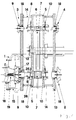
- the geared compressor shown serves to compress oxygen and contains four compressor stages, one of which is shown in Fig. 1, the first and third compressor stages 1, 3 are shown on the left, while the second and fourth compressor stages 2, 4 are only indicated by stub shafts.
- Compressor stages 1 to 4 are driven by an integrated oil-lubricated gear.
- the transmission contains a central drive gear 6 within a transmission housing 5, with which pinions 7 are engaged.
- Each pinion 7 is seated on a rotor shaft 8, the end of which faces away from the pinion 7 carries an impeller 9 of a compressor stage 1 to 4.
- Each rotor shaft 8 is mounted on the side facing away from the impeller 9 in the gear housing 5 in an oil-lubricated bearing 10 designed as a tilting segment bearing.
- the passage of the rotor shaft 8 through the gear housing 5 is sealed against the free atmosphere on one side by an end cap 11 and on the other side by a shaft seal 12 loaded with sealing air.
- a free-standing holding structure designed as a plate 13 is arranged on two opposite sides at a distance from the gear housing 5.
- the plates 13 are connected to the gear housing 5 via spacers 14 and stand together with the gear housing 5 on a foundation (not shown). An intermediate space through which ambient air flows is thus formed between the plates 13.
- Each compressor stage 1 to 4 contains an impeller 9 which rotates in a compressor housing 15.
- the compressor housing 15 is provided with an inlet part 16 and closed on the rear side by a rear wall 17.
- the rear wall 17 of the compressor housing 15 is fastened to the plate 13, so that the plates 13 carry the compressor stages 1 to 4.
- each compressor stage 1 to 4 passes through the plate 13 and is supported here in an additional bearing 18.
- a bearing a hydraulic tilting segment bearing can be used, which, for example, with a lubricant compatible with oxygen.
- B. water is lubricated.
- the additional bearing 18 can also be designed as a magnetic bearing.
- Such magnetic bearings are known. They guide the shaft by means of controlled magnetic fields. The rotor shaft 8 is guided precisely and self-balancing by these magnetic bearings.
- auxiliary bearing is arranged in the inlet part 16 of the compressor housing 15.
- the auxiliary bearing consists of a conical catch bearing 19, which contains a conical bearing ring 20, is supported on rollers 21 and surrounds a conical section of the hub 22 of the impeller 9.
- the conical bearing ring 20 of the backup bearing 19 is held by means of an electromagnet 23 against the force of a spring 24 at a distance from the item 22.
- the electromagnet 23 becomes ineffective and the spring 24 presses the conical bearing ring 20 against the handle 22, as a result of which the impeller 9 is guided without play and can run out safely.
- the rotor shaft 8 is sealed from the outside atmosphere within the rear wall 17 of the compressor housing 15 by a short shaft seal 25, which is designed as a ceramic, dry, gas-lubricated floating ring seal.
- the leakage oxygen can be directed into an exhaust system together with sealing air. It could also easily escape into the machine shop. Compared to oil-lubricated bearings, this design principle allows rotors with larger diameters to be sealed.
- the described storage of the rotor shaft 8 in the additional bearing 18 in the plate 13 and in the oil-lubricated bearing 10 in the gear housing 5 with the arrangement of only one impeller 9 per rotor shaft 8 results in favorable lever ratios in the oil-lubricated bearing 10.
- the Rotor shaft 8, as shown in Fig. 3 can also be mounted in a further oil-lubricated bearing 26, which on the other side of the pinion 7 is arranged in the gear housing 5.
- the additional bearing 18 has the function of a guide and damping bearing in particular when using a magnetic bearing.
- each rotor shaft 8 driven by a pinion 7 carries two impellers 9. Behind each of the L-impellers 9 arranged in this way there is an additional bearing designed as a magnetic bearing, which acts as a guide and damping bearing.
- the rotor shaft 8 By mounting the rotor shaft 8 very close to the impeller 9, there is a very small overhang of the center of gravity of the impeller 9. At the same time, the diameter of the rotor shaft 8 is increased, which is favored by the use of a ceramic, dry, gas-lubricated floating ring seal as the shaft seal 25.
- the small overhang of the center of gravity of the impeller and the enlarged diameter of the rotor shaft 8 reduce the susceptibility to vibration of the impeller 9, so that larger vibration amplitudes are avoided and smooth running is achieved.
- the large space containing ambient air between the gear housing 5 carrying lubricating oil and the oxygen-promoting compressor stages 1 to 4 ensures a clean separation of lubricating oil and oxygen.
- the invention can therefore also be used for the compression of gases other than oxygen if an absolute oil-free nature of the compressed gas is required in the range of a few ppm.
Landscapes
- Engineering & Computer Science (AREA)
- Mechanical Engineering (AREA)
- General Engineering & Computer Science (AREA)
- Structures Of Non-Positive Displacement Pumps (AREA)
- Applications Or Details Of Rotary Compressors (AREA)
- Rotary Pumps (AREA)
- Oxygen, Ozone, And Oxides In General (AREA)
Applications Claiming Priority (2)
| Application Number | Priority Date | Filing Date | Title |
|---|---|---|---|
| DE4339060A DE4339060A1 (de) | 1993-11-16 | 1993-11-16 | Getriebeverdichter für die Verdichtung von Sauerstoff |
| DE4339060 | 1993-11-16 |
Publications (2)
| Publication Number | Publication Date |
|---|---|
| EP0653566A1 true EP0653566A1 (fr) | 1995-05-17 |
| EP0653566B1 EP0653566B1 (fr) | 1998-12-23 |
Family
ID=6502689
Family Applications (1)
| Application Number | Title | Priority Date | Filing Date |
|---|---|---|---|
| EP94112720A Expired - Lifetime EP0653566B1 (fr) | 1993-11-16 | 1994-08-16 | Compresseur et transmission pour le compression d'oxygène |
Country Status (9)
| Country | Link |
|---|---|
| US (1) | US5503523A (fr) |
| EP (1) | EP0653566B1 (fr) |
| JP (1) | JPH08226399A (fr) |
| CZ (1) | CZ286941B6 (fr) |
| DE (2) | DE4339060A1 (fr) |
| PL (1) | PL174005B1 (fr) |
| RU (1) | RU2082022C1 (fr) |
| SK (1) | SK280754B6 (fr) |
| UA (1) | UA37208C2 (fr) |
Cited By (4)
| Publication number | Priority date | Publication date | Assignee | Title |
|---|---|---|---|---|
| WO1997023731A1 (fr) * | 1995-12-21 | 1997-07-03 | Comoti-National Research & Design Institute For Turboengines | Compresseur centrifuge a boite d'engrenage incorpore |
| WO2011141439A1 (fr) * | 2010-05-11 | 2011-11-17 | Siemens Aktiengesellschaft | Compresseur à engrenage multiétagé |
| CN110966238A (zh) * | 2019-12-19 | 2020-04-07 | 上海菲恒生活用品有限公司 | 一种可语音控制的风扇 |
| EP3705725A1 (fr) * | 2019-03-05 | 2020-09-09 | Siemens Aktiengesellschaft | Agencement pourvu de composants de l'engrenage |
Families Citing this family (11)
| Publication number | Priority date | Publication date | Assignee | Title |
|---|---|---|---|---|
| US6273429B1 (en) | 1998-07-09 | 2001-08-14 | Atlas Copco Aktiebolag | Labyrinth cartridge seal, and centrifugal compressor applications thereof |
| US6174167B1 (en) | 1998-12-01 | 2001-01-16 | Woehrle Peter S. | Bioroot endosseous implant |
| RU2166187C2 (ru) * | 1999-07-14 | 2001-04-27 | Федеральное государственное унитарное предприятие "Исследовательский Центр им. М.В. Келдыша" | Установка для испытаний образцов материалов и элементов конструкций в среде жидкого или газообразного кислорода с моделированием натурных условий эксплуатации |
| US6393865B1 (en) * | 2000-09-27 | 2002-05-28 | Air Products And Chemicals, Inc. | Combined service main air/product compressor |
| AU2003202961C1 (en) | 2002-01-11 | 2009-03-26 | Nobel Biocare Services Ag | Dental implant system |
| USD507052S1 (en) | 2003-04-01 | 2005-07-05 | Peter S. Wohrle | Dental implant |
| US7708559B2 (en) | 2003-05-16 | 2010-05-04 | Nobel Biocare Services Ag | Dental implant system |
| USD511833S1 (en) | 2003-10-01 | 2005-11-22 | Woehrle Peter S | Dental implant |
| DE102015204466A1 (de) | 2015-03-12 | 2016-09-15 | Siemens Aktiengesellschaft | Anordnung mit zwei Verdichtern, Verfahren zum Nachrüsten |
| CN105257591B (zh) * | 2015-11-09 | 2017-11-28 | 江苏杰尔科技股份有限公司 | 一种单级高速离心风机的叶轮安装结构 |
| RU174575U1 (ru) * | 2016-11-15 | 2017-10-20 | Публичное акционерное общество "Сумское машиностроительное научно-производственное объединение" | Мультипликаторный центробежный компрессор |
Citations (7)
| Publication number | Priority date | Publication date | Assignee | Title |
|---|---|---|---|---|
| DE909853C (de) * | 1948-10-02 | 1954-04-26 | Arthur Naumann | Mehrstufiger Kreiselverdichter |
| US3355096A (en) * | 1966-02-15 | 1967-11-28 | Ingersoll Rand Co | Multi-stage intercooled compressor |
| US3387769A (en) * | 1966-10-03 | 1968-06-11 | Worthington Corp | Multistage turbomachine |
| US3476485A (en) * | 1967-09-18 | 1969-11-04 | Dresser Ind | Multistage centrifugal compressor |
| CH486647A (de) * | 1966-04-23 | 1970-02-28 | Hoechst Ag | Verbundsystem aus harten Platten mit schwingungsdämpfender Zwischenschicht |
| DE2256681A1 (de) * | 1972-11-18 | 1974-06-06 | Demag Ag | Turboverdichter |
| EP0440902A1 (fr) * | 1990-02-06 | 1991-08-14 | Deutsche Babcock- Borsig Aktiengesellschaft | Transmission et compresseur centrifuge |
Family Cites Families (6)
| Publication number | Priority date | Publication date | Assignee | Title |
|---|---|---|---|---|
| US2625883A (en) * | 1951-01-25 | 1953-01-20 | Julia M Howser | Centrifugal pump drive and seal means |
| US3077296A (en) * | 1961-04-26 | 1963-02-12 | Schwitzer Corp | Turbocharger oil seal |
| GB993668A (en) * | 1962-04-26 | 1965-06-02 | Hayward Tyler & Company Ltd | Improvements in or relating to electric motor and pump units |
| CH606801A5 (fr) * | 1975-12-02 | 1978-11-15 | Escher Wyss Ag | |
| US4439096A (en) * | 1982-08-13 | 1984-03-27 | A. W. Chesterton Company | Impeller adjuster for centrifugal pump |
| US5319273A (en) * | 1992-10-26 | 1994-06-07 | Satcon Technology Corporation | Fixed gain electromagnetic actuator and electromagnetic bearing incorporating same |
-
1993
- 1993-11-16 DE DE4339060A patent/DE4339060A1/de not_active Withdrawn
-
1994
- 1994-08-05 SK SK937-94A patent/SK280754B6/sk unknown
- 1994-08-10 CZ CZ19941933A patent/CZ286941B6/cs not_active IP Right Cessation
- 1994-08-16 EP EP94112720A patent/EP0653566B1/fr not_active Expired - Lifetime
- 1994-08-16 DE DE59407534T patent/DE59407534D1/de not_active Expired - Fee Related
- 1994-09-09 US US08/303,384 patent/US5503523A/en not_active Expired - Fee Related
- 1994-10-19 JP JP6280013A patent/JPH08226399A/ja not_active Ceased
- 1994-11-14 PL PL94305839A patent/PL174005B1/pl unknown
- 1994-11-14 RU RU9494041733A patent/RU2082022C1/ru not_active IP Right Cessation
- 1994-11-15 UA UA94119024A patent/UA37208C2/uk unknown
Patent Citations (7)
| Publication number | Priority date | Publication date | Assignee | Title |
|---|---|---|---|---|
| DE909853C (de) * | 1948-10-02 | 1954-04-26 | Arthur Naumann | Mehrstufiger Kreiselverdichter |
| US3355096A (en) * | 1966-02-15 | 1967-11-28 | Ingersoll Rand Co | Multi-stage intercooled compressor |
| CH486647A (de) * | 1966-04-23 | 1970-02-28 | Hoechst Ag | Verbundsystem aus harten Platten mit schwingungsdämpfender Zwischenschicht |
| US3387769A (en) * | 1966-10-03 | 1968-06-11 | Worthington Corp | Multistage turbomachine |
| US3476485A (en) * | 1967-09-18 | 1969-11-04 | Dresser Ind | Multistage centrifugal compressor |
| DE2256681A1 (de) * | 1972-11-18 | 1974-06-06 | Demag Ag | Turboverdichter |
| EP0440902A1 (fr) * | 1990-02-06 | 1991-08-14 | Deutsche Babcock- Borsig Aktiengesellschaft | Transmission et compresseur centrifuge |
Non-Patent Citations (1)
| Title |
|---|
| "The Centregal High-Pressure Centrifugal Compression.", COMPRESSED AIR MAGAZINE, vol. 83, no. 5, May 1978 (1978-05-01) * |
Cited By (6)
| Publication number | Priority date | Publication date | Assignee | Title |
|---|---|---|---|---|
| WO1997023731A1 (fr) * | 1995-12-21 | 1997-07-03 | Comoti-National Research & Design Institute For Turboengines | Compresseur centrifuge a boite d'engrenage incorpore |
| WO2011141439A1 (fr) * | 2010-05-11 | 2011-11-17 | Siemens Aktiengesellschaft | Compresseur à engrenage multiétagé |
| US9512849B2 (en) | 2010-05-11 | 2016-12-06 | Siemens Aktiengesellschaft | Multi-stage integrally geared compressor |
| EP3705725A1 (fr) * | 2019-03-05 | 2020-09-09 | Siemens Aktiengesellschaft | Agencement pourvu de composants de l'engrenage |
| CN110966238A (zh) * | 2019-12-19 | 2020-04-07 | 上海菲恒生活用品有限公司 | 一种可语音控制的风扇 |
| CN110966238B (zh) * | 2019-12-19 | 2020-07-28 | 萧县亿达信息科技有限公司 | 一种可语音控制的风扇 |
Also Published As
| Publication number | Publication date |
|---|---|
| CZ286941B6 (en) | 2000-08-16 |
| RU94041733A (ru) | 1996-11-10 |
| RU2082022C1 (ru) | 1997-06-20 |
| UA37208C2 (uk) | 2001-05-15 |
| PL305839A1 (en) | 1995-05-29 |
| EP0653566B1 (fr) | 1998-12-23 |
| DE4339060A1 (de) | 1995-05-18 |
| DE59407534D1 (de) | 1999-02-04 |
| SK280754B6 (sk) | 2000-07-11 |
| JPH08226399A (ja) | 1996-09-03 |
| SK93794A3 (en) | 1995-06-07 |
| US5503523A (en) | 1996-04-02 |
| CZ193394A3 (en) | 1995-05-17 |
| PL174005B1 (pl) | 1998-05-29 |
Similar Documents
| Publication | Publication Date | Title |
|---|---|---|
| EP0653566B1 (fr) | Compresseur et transmission pour le compression d'oxygène | |
| EP1074746B1 (fr) | Turbo-compresseur | |
| DE2416639A1 (de) | Rotierende montageanordnung | |
| EP0592803A1 (fr) | Compresseur à arbres multiples et transmission avec des canaux de retour et avec diffuseur radial | |
| DE2349033A1 (de) | Turbomolekularpumpe | |
| DE3326910A1 (de) | Oelfreier rotationsverdraengungskompressor | |
| DE102010054905A1 (de) | Lagereinheit für einen Turbolader | |
| DE29516599U1 (de) | Reibungsvakuumpumpe mit Zwischeneinlaß | |
| WO1993023672A1 (fr) | Pompe a friction a vide a gaz | |
| DE69008967T2 (de) | Turbogebläse für laser und laseroszillatoren. | |
| WO2001057403A1 (fr) | Joint dynamique | |
| DE2315093A1 (de) | Maschine zur foerderung bzw. verdichtung von gasen | |
| EP1090231A1 (fr) | Pompe a vide rotative munie d'un chassis, d'un rotor et d'un carter, et dispositif pourvu d'une pompe a vide rotative de ce type | |
| EP3657021A1 (fr) | Pompe à vide | |
| EP1067290B1 (fr) | Pompe à vide | |
| DE10003018B4 (de) | Turboverdichter | |
| DE3722164A1 (de) | Turbomolekularpumpe | |
| EP0290664B1 (fr) | Pompe à deux arbres | |
| DE4327506A1 (de) | Turbovakuumpumpe | |
| DE60319585T2 (de) | Vakuumpumpe | |
| DE3321718A1 (de) | Waelzkolbenpumpe | |
| WO2010015501A1 (fr) | Utilisation d'un palier à roulement pour supporter des composants rotatifs dans des appareils à vide et appareil à vide | |
| DE2409857B2 (de) | Turbomolekularvakuumpumpe mit zumindest teilweise glockenfoermig ausgebildetem rotor | |
| EP2949938A1 (fr) | Pompe à vide | |
| EP1119709A1 (fr) | Pompe a vide a friction avec stator et rotor |
Legal Events
| Date | Code | Title | Description |
|---|---|---|---|
| PUAI | Public reference made under article 153(3) epc to a published international application that has entered the european phase |
Free format text: ORIGINAL CODE: 0009012 |
|
| AK | Designated contracting states |
Kind code of ref document: A1 Designated state(s): CH DE FR GB IT LI |
|
| 17P | Request for examination filed |
Effective date: 19950323 |
|
| 17Q | First examination report despatched |
Effective date: 19960905 |
|
| GRAG | Despatch of communication of intention to grant |
Free format text: ORIGINAL CODE: EPIDOS AGRA |
|
| RAP1 | Party data changed (applicant data changed or rights of an application transferred) |
Owner name: GHH BORSIG TURBOMASCHINEN GMBH |
|
| GRAG | Despatch of communication of intention to grant |
Free format text: ORIGINAL CODE: EPIDOS AGRA |
|
| GRAH | Despatch of communication of intention to grant a patent |
Free format text: ORIGINAL CODE: EPIDOS IGRA |
|
| GRAH | Despatch of communication of intention to grant a patent |
Free format text: ORIGINAL CODE: EPIDOS IGRA |
|
| GRAA | (expected) grant |
Free format text: ORIGINAL CODE: 0009210 |
|
| AK | Designated contracting states |
Kind code of ref document: B1 Designated state(s): CH DE FR GB IT LI |
|
| REG | Reference to a national code |
Ref country code: CH Ref legal event code: EP |
|
| GBT | Gb: translation of ep patent filed (gb section 77(6)(a)/1977) |
Effective date: 19981223 |
|
| REF | Corresponds to: |
Ref document number: 59407534 Country of ref document: DE Date of ref document: 19990204 |
|
| ET | Fr: translation filed | ||
| ITF | It: translation for a ep patent filed | ||
| PLBE | No opposition filed within time limit |
Free format text: ORIGINAL CODE: 0009261 |
|
| STAA | Information on the status of an ep patent application or granted ep patent |
Free format text: STATUS: NO OPPOSITION FILED WITHIN TIME LIMIT |
|
| 26N | No opposition filed | ||
| REG | Reference to a national code |
Ref country code: GB Ref legal event code: IF02 |
|
| PGFP | Annual fee paid to national office [announced via postgrant information from national office to epo] |
Ref country code: GB Payment date: 20030728 Year of fee payment: 10 Ref country code: CH Payment date: 20030728 Year of fee payment: 10 |
|
| PGFP | Annual fee paid to national office [announced via postgrant information from national office to epo] |
Ref country code: DE Payment date: 20030805 Year of fee payment: 10 |
|
| PGFP | Annual fee paid to national office [announced via postgrant information from national office to epo] |
Ref country code: FR Payment date: 20030813 Year of fee payment: 10 |
|
| PG25 | Lapsed in a contracting state [announced via postgrant information from national office to epo] |
Ref country code: GB Free format text: LAPSE BECAUSE OF NON-PAYMENT OF DUE FEES Effective date: 20040816 |
|
| PG25 | Lapsed in a contracting state [announced via postgrant information from national office to epo] |
Ref country code: LI Free format text: LAPSE BECAUSE OF NON-PAYMENT OF DUE FEES Effective date: 20040831 Ref country code: CH Free format text: LAPSE BECAUSE OF NON-PAYMENT OF DUE FEES Effective date: 20040831 |
|
| PG25 | Lapsed in a contracting state [announced via postgrant information from national office to epo] |
Ref country code: DE Free format text: LAPSE BECAUSE OF NON-PAYMENT OF DUE FEES Effective date: 20050301 |
|
| GBPC | Gb: european patent ceased through non-payment of renewal fee |
Effective date: 20040816 |
|
| REG | Reference to a national code |
Ref country code: CH Ref legal event code: PL |
|
| PG25 | Lapsed in a contracting state [announced via postgrant information from national office to epo] |
Ref country code: FR Free format text: LAPSE BECAUSE OF NON-PAYMENT OF DUE FEES Effective date: 20050429 |
|
| REG | Reference to a national code |
Ref country code: FR Ref legal event code: ST |
|
| PG25 | Lapsed in a contracting state [announced via postgrant information from national office to epo] |
Ref country code: IT Free format text: LAPSE BECAUSE OF NON-PAYMENT OF DUE FEES;WARNING: LAPSES OF ITALIAN PATENTS WITH EFFECTIVE DATE BEFORE 2007 MAY HAVE OCCURRED AT ANY TIME BEFORE 2007. THE CORRECT EFFECTIVE DATE MAY BE DIFFERENT FROM THE ONE RECORDED. Effective date: 20050816 |