EP0653604A1 - Entfaltungseinrichtung für Stabilisatorflügel eines Raketengeschosses - Google Patents
Entfaltungseinrichtung für Stabilisatorflügel eines Raketengeschosses Download PDFInfo
- Publication number
- EP0653604A1 EP0653604A1 EP94402075A EP94402075A EP0653604A1 EP 0653604 A1 EP0653604 A1 EP 0653604A1 EP 94402075 A EP94402075 A EP 94402075A EP 94402075 A EP94402075 A EP 94402075A EP 0653604 A1 EP0653604 A1 EP 0653604A1
- Authority
- EP
- European Patent Office
- Prior art keywords
- spring
- fin
- projectile
- support
- deployment
- Prior art date
- Legal status (The legal status is an assumption and is not a legal conclusion. Google has not performed a legal analysis and makes no representation as to the accuracy of the status listed.)
- Granted
Links
- 230000003019 stabilising effect Effects 0.000 title 1
- 230000006641 stabilisation Effects 0.000 claims description 5
- 238000011105 stabilization Methods 0.000 claims description 5
- 230000035515 penetration Effects 0.000 claims description 2
- 230000000977 initiatory effect Effects 0.000 description 2
- 235000014755 Eruca sativa Nutrition 0.000 description 1
- 244000024675 Eruca sativa Species 0.000 description 1
- 238000004026 adhesive bonding Methods 0.000 description 1
- 230000000694 effects Effects 0.000 description 1
- 230000002452 interceptive effect Effects 0.000 description 1
- 238000003754 machining Methods 0.000 description 1
- 238000004519 manufacturing process Methods 0.000 description 1
- 230000000087 stabilizing effect Effects 0.000 description 1
Images


Classifications
-
- F—MECHANICAL ENGINEERING; LIGHTING; HEATING; WEAPONS; BLASTING
- F42—AMMUNITION; BLASTING
- F42B—EXPLOSIVE CHARGES, e.g. FOR BLASTING, FIREWORKS, AMMUNITION
- F42B10/00—Means for influencing, e.g. improving, the aerodynamic properties of projectiles or missiles; Arrangements on projectiles or missiles for stabilising, steering, range-reducing, range-increasing or fall-retarding
- F42B10/02—Stabilising arrangements
- F42B10/14—Stabilising arrangements using fins spread or deployed after launch, e.g. after leaving the barrel
Definitions
- the technical field of the invention is that of devices for deploying projectile fins, in particular of the rocket type.
- the stabilization of such projectiles is generally ensured by a tail unit of diameter corresponding substantially to the internal diameter of the launching tube of the projectile considered.
- Patent FR7803397 describes such a projectile in which each fin is deployed by an elastic member.
- This member is a spring in the form of a curved wire, placed in a groove made under each fin. At the exit of the launch tube, the spring relaxes by pushing back the fin and thus ensures its deployment. But this device requires the production of a groove intended to accommodate the lower part of the fin and the spring and to maintain the latter during the deployment of the fin.
- Patent EP0202734 proposes to deploy the fins by an elastic member forming an integral part of the fin itself. For this it is planned to make a tongue on each fin. This device has the drawback of requiring precise machining of the fin and of using for this material a material having good elastic qualities, therefore a high cost.
- the object of the invention is therefore to produce a device for deploying stabilizing fins which does not have such drawbacks.
- the device makes it possible in particular, by a reduced radial size, to ensure maximum opening torque. It also makes it possible to cause the least aerodynamic disturbance possible.
- the subject of the invention is a deployment device for a stabilization wing of a projectile, characterized in that it comprises a torsion spring whose axis is parallel to the axis of the projectile.
- the spring is disposed in a groove formed in a flange of a support integral with the projectile, on which the fin is mounted, the groove having a width greater than the external diameter of the spring, making it possible to guide the latter. ci and authorizing its ejection after deployment of the fin.
- the spring has at one of its ends, a part bent at 90 ° and with an axis parallel to the axis of the spring and is radially integral with the support by penetration of the bent part in an orifice made in the rear face of the support, orifice with an axis parallel to the axis of the projectile and having a diameter greater than the diameter of the wire constituting the spring, allowing the ejection of the latter after deployment of the fin.
- the rear face of the support has a clearance connecting the groove to the orifice and allowing passage of the end of the spring, a clearance having a depth and a width greater than the diameter of the wire constituting the spring, allowing the latter to be ejected after deployment of the fin.
- the other end of the spring is close to the flange and in abutment with a lower face of the fin, the spring being held axially by the flange and constrained in torsion when the fin is folded and exerting a force capable of making pivot it relative to the support so as to deploy it.
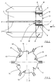
- FIG. 1 schematically represents a projectile 1, of rocket type, placed in a launching tube 2.
- the projectile is conventionally constituted by a body 3 provided with a warhead 4 at the front.
- the body 3 includes a military charge which is generally a hollow charge (not shown).
- fins 16 regularly angularly distributed (here 6 in number).
- the rear of the projectile comprises a fin support 5 consisting of a cylindrical surface 19 and an annular flange 17.
- the cylindrical surface 19 of the fin support is adjusted inside a bore 20, produced at the rear part of the body 3, and the collar 17 is in abutment against the rear face of the body. This makes it possible to secure, for example by gluing, the fin support 5 on the body 3.
- the fin support 5 comprises, at its annular flange 17, a tail unit 6 of diameter substantially equal to the internal diameter of the projectile launching tube.
- the empennage 6 is composed of stabilization fins 7 (here 6 in number).
- the collar 17 comprises, at its external diameter, yokes 18 which receive the fins 7 pivotally mounted around an axis 8.
- the fins 7 are deployed at the outlet of the launch tube under the action of a deployment device which will be described later.
- the yokes 18 and the fins 16 guide the projectile during its propulsion inside the launching tube.
- FIG. 2 represents the fin support 5 equipped with its tail unit 6, in the position it occupies when it is placed in the launching tube, ie stabilization fins folded down along the body of the projectile.
- the empennage 6 comprises six fins 7 regularly angularly spaced.
- a cylindrical torsion spring 9 with angular action is placed near each fin and serves as an elastic member allowing the deployment thereof. It is disposed inside a groove 10, arranged in the flange 17 of the fin support 5, parallel to the axis XX 'of the projectile.
- the groove 10, which is intended to guide the cylindrical spring 9 has a width greater than the outside diameter of the spring, in order to allow the ejection of the latter.
- FIG. 3 represents the fin support 5 alone in the direction F of FIG. 2.
- the rear face 13 of the fin support 5 has, at each groove 10, an orifice 14 with an axis parallel to the axis XX 'of the projectile and a clearance 15 connecting the orifice to the groove
- the end 12 of the spring comprises a part 21 bent at 90 °, with an axis parallel to the axis YY 'of the spring (see FIG. 5).
- the end 12 of the spring 9 passes through the clearance 15 which has a depth and a width slightly greater than the diameter of the wire of the spring 9, so that it is set back relative to the rear face 13 of the fin support.
- the bent part 21 penetrates inside the orifice 14 which has a diameter slightly greater than the diameter of the wire composing the spring.
- the spring is thus guided by the groove 10 and radially integral with the fin support by the clearance 15 and the orifice 14.
- the cylindrical spring with angular action is constrained in torsion. It exerts a force on the fin, which makes it possible, as soon as the projectile leaves the launching tube, to initiate the deployment of each corresponding fin.
Landscapes
- Physics & Mathematics (AREA)
- Fluid Mechanics (AREA)
- Engineering & Computer Science (AREA)
- General Engineering & Computer Science (AREA)
- Toys (AREA)
Applications Claiming Priority (2)
| Application Number | Priority Date | Filing Date | Title |
|---|---|---|---|
| FR9313617 | 1993-11-16 | ||
| FR9313617A FR2712679B1 (fr) | 1993-11-16 | 1993-11-16 | Dispositif de déploiement pour une ailette de stabilisation de projectile de type roquette. |
Publications (2)
| Publication Number | Publication Date |
|---|---|
| EP0653604A1 true EP0653604A1 (de) | 1995-05-17 |
| EP0653604B1 EP0653604B1 (de) | 1998-07-29 |
Family
ID=9452873
Family Applications (1)
| Application Number | Title | Priority Date | Filing Date |
|---|---|---|---|
| EP19940402075 Expired - Lifetime EP0653604B1 (de) | 1993-11-16 | 1994-09-19 | Entfaltungseinrichtung für Stabilisatorflügel eines Raketengeschosses |
Country Status (3)
| Country | Link |
|---|---|
| EP (1) | EP0653604B1 (de) |
| DE (1) | DE69412036T2 (de) |
| FR (1) | FR2712679B1 (de) |
Cited By (2)
| Publication number | Priority date | Publication date | Assignee | Title |
|---|---|---|---|---|
| EP3032212A1 (de) * | 2014-12-11 | 2016-06-15 | MBDA Deutschland GmbH | Rudersystem |
| US10006748B2 (en) | 2014-12-11 | 2018-06-26 | Mbda Deutschland Gmbh | Rudder system |
Families Citing this family (2)
| Publication number | Priority date | Publication date | Assignee | Title |
|---|---|---|---|---|
| RU2125702C1 (ru) * | 1998-03-16 | 1999-01-27 | Государственное научно-производственное предприятие "Сплав" | Аэродинамический стабилизатор реактивного снаряда залпового огня |
| SG101481A1 (en) * | 2001-09-18 | 2004-01-30 | Singapore Tech Dynamics Pte | A foldable wing structure for airborne vehicle or the like |
Citations (4)
| Publication number | Priority date | Publication date | Assignee | Title |
|---|---|---|---|---|
| FR2241761A1 (de) * | 1973-08-24 | 1975-03-21 | Rheinmetall Gmbh | |
| FR2380532A1 (fr) * | 1977-02-09 | 1978-09-08 | Bofors Ab | Empennage de projectile a ailettes escamotables |
| US4523728A (en) * | 1983-03-07 | 1985-06-18 | Ford Aerospace & Communications Corporation | Passive auto-erecting alignment wings for long rod penetrator |
| EP0202734A1 (de) * | 1985-03-23 | 1986-11-26 | British Aerospace Public Limited Company | Vorrichtung zum Ausfahren von Flossen |
-
1993
- 1993-11-16 FR FR9313617A patent/FR2712679B1/fr not_active Expired - Fee Related
-
1994
- 1994-09-19 DE DE1994612036 patent/DE69412036T2/de not_active Expired - Fee Related
- 1994-09-19 EP EP19940402075 patent/EP0653604B1/de not_active Expired - Lifetime
Patent Citations (4)
| Publication number | Priority date | Publication date | Assignee | Title |
|---|---|---|---|---|
| FR2241761A1 (de) * | 1973-08-24 | 1975-03-21 | Rheinmetall Gmbh | |
| FR2380532A1 (fr) * | 1977-02-09 | 1978-09-08 | Bofors Ab | Empennage de projectile a ailettes escamotables |
| US4523728A (en) * | 1983-03-07 | 1985-06-18 | Ford Aerospace & Communications Corporation | Passive auto-erecting alignment wings for long rod penetrator |
| EP0202734A1 (de) * | 1985-03-23 | 1986-11-26 | British Aerospace Public Limited Company | Vorrichtung zum Ausfahren von Flossen |
Cited By (2)
| Publication number | Priority date | Publication date | Assignee | Title |
|---|---|---|---|---|
| EP3032212A1 (de) * | 2014-12-11 | 2016-06-15 | MBDA Deutschland GmbH | Rudersystem |
| US10006748B2 (en) | 2014-12-11 | 2018-06-26 | Mbda Deutschland Gmbh | Rudder system |
Also Published As
| Publication number | Publication date |
|---|---|
| FR2712679B1 (fr) | 1996-02-09 |
| EP0653604B1 (de) | 1998-07-29 |
| FR2712679A1 (fr) | 1995-05-24 |
| DE69412036T2 (de) | 1998-12-03 |
| DE69412036D1 (de) | 1998-09-03 |
Similar Documents
| Publication | Publication Date | Title |
|---|---|---|
| EP0905473B1 (de) | Grosskalibriges und weitreichendes Artilleriegeschoss | |
| EP0434505B1 (de) | Peripheriemantel für einen rohrabgeschossenen gelenkten Flugkörper | |
| EP0690284B1 (de) | Aufspreizvorrichtung für den Flügel eines Geschosses | |
| FR2864613A1 (fr) | Dispositif de deploiement et d'entrainement de gouvernes d'un projectile | |
| FR2578640A1 (fr) | Missile a empennage surcalibre | |
| EP0870105B1 (de) | Ausfahrbare raketentriebwerkdüse | |
| EP1045221B1 (de) | Bremsvorrichtung für die Flugbahngeschwindigkeit eines Geschosses | |
| EP0454545B1 (de) | Vorrichtung zur zeitlich begrenzten mechanischen Ankuppelung sowie zur raschen Trennung eines an einem Träger befestigten abstossbaren Gegenstandes | |
| EP0653604B1 (de) | Entfaltungseinrichtung für Stabilisatorflügel eines Raketengeschosses | |
| EP0541412B1 (de) | Trägergeschoss mit einem Kolben zum Auswerfen einer Submunition | |
| FR2609165A1 (fr) | Projectile comportant des sous-projectiles a zone d'efficacite predefinie | |
| FR2796454A1 (fr) | Arme montee sur un aeronef furtif et pourvue d'un missile, ainsi qu'un systeme d'arme comprenant un aeronef furtif et une telle arme | |
| FR2661464A1 (fr) | Dispositif d'assujettissement temporaire d'un objet a un support, a zone de rupture calibree en traction. | |
| FR2748804A1 (fr) | Tete de combat en tandem | |
| EP1369349B1 (de) | Waffe, die eine Rakete enthält, und die an einem Tarnkappen-Flugzeug montiert ist, und Waffensystem, das ein Tarnkappen-Flugzeug und eine solche Waffe enthält | |
| EP1376045B1 (de) | Vorrichtung zum Adaptieren eines aus einem Rohr abzuschiessenden Projektils | |
| EP2569591A1 (de) | Gelenkte munition mit aerodynamischem kappenschutz | |
| EP0811823B1 (de) | Explosives Geschoss | |
| FR2672673A1 (fr) | Dispositif d'amorcage pour un sous-projectile. | |
| EP3910280B1 (de) | Vorrichtung zur erkennung des fehlens einer mechanischen barriere für einen flugkörper und flugkörper mit einer solchen vorrichtung | |
| EP1548392A1 (de) | Vorrichtung zur Entfaltung der Steuerflächen eines Projektils | |
| FR3037390A1 (fr) | Dispositif de stabilisation et projectile equipe d'un tel dispositif | |
| FR2874254A1 (fr) | Armes guidees | |
| FR2682753A1 (fr) | Dispositif pour stabiliser aerodynamiquement une bombelette et bombelette ainsi equipee. | |
| CH506770A (fr) | Projectile comprenant un empennage déployant |
Legal Events
| Date | Code | Title | Description |
|---|---|---|---|
| PUAI | Public reference made under article 153(3) epc to a published international application that has entered the european phase |
Free format text: ORIGINAL CODE: 0009012 |
|
| AK | Designated contracting states |
Kind code of ref document: A1 Designated state(s): DE GB SE |
|
| 17P | Request for examination filed |
Effective date: 19950701 |
|
| 17Q | First examination report despatched |
Effective date: 19970203 |
|
| GRAG | Despatch of communication of intention to grant |
Free format text: ORIGINAL CODE: EPIDOS AGRA |
|
| GRAG | Despatch of communication of intention to grant |
Free format text: ORIGINAL CODE: EPIDOS AGRA |
|
| GRAH | Despatch of communication of intention to grant a patent |
Free format text: ORIGINAL CODE: EPIDOS IGRA |
|
| GRAH | Despatch of communication of intention to grant a patent |
Free format text: ORIGINAL CODE: EPIDOS IGRA |
|
| GRAA | (expected) grant |
Free format text: ORIGINAL CODE: 0009210 |
|
| AK | Designated contracting states |
Kind code of ref document: B1 Designated state(s): DE GB SE |
|
| GBT | Gb: translation of ep patent filed (gb section 77(6)(a)/1977) |
Effective date: 19980729 |
|
| REF | Corresponds to: |
Ref document number: 69412036 Country of ref document: DE Date of ref document: 19980903 |
|
| PLBE | No opposition filed within time limit |
Free format text: ORIGINAL CODE: 0009261 |
|
| STAA | Information on the status of an ep patent application or granted ep patent |
Free format text: STATUS: NO OPPOSITION FILED WITHIN TIME LIMIT |
|
| 26N | No opposition filed | ||
| REG | Reference to a national code |
Ref country code: GB Ref legal event code: IF02 |
|
| PGFP | Annual fee paid to national office [announced via postgrant information from national office to epo] |
Ref country code: SE Payment date: 20030825 Year of fee payment: 10 |
|
| PGFP | Annual fee paid to national office [announced via postgrant information from national office to epo] |
Ref country code: GB Payment date: 20030829 Year of fee payment: 10 |
|
| PGFP | Annual fee paid to national office [announced via postgrant information from national office to epo] |
Ref country code: DE Payment date: 20030909 Year of fee payment: 10 |
|
| PG25 | Lapsed in a contracting state [announced via postgrant information from national office to epo] |
Ref country code: GB Free format text: LAPSE BECAUSE OF NON-PAYMENT OF DUE FEES Effective date: 20040919 |
|
| PG25 | Lapsed in a contracting state [announced via postgrant information from national office to epo] |
Ref country code: SE Free format text: LAPSE BECAUSE OF NON-PAYMENT OF DUE FEES Effective date: 20040920 |
|
| PG25 | Lapsed in a contracting state [announced via postgrant information from national office to epo] |
Ref country code: DE Free format text: LAPSE BECAUSE OF NON-PAYMENT OF DUE FEES Effective date: 20050401 |
|
| EUG | Se: european patent has lapsed | ||
| GBPC | Gb: european patent ceased through non-payment of renewal fee |
Effective date: 20040919 |