EP0653643A2 - Procédé et système pour surveiller des véhicules - Google Patents
Procédé et système pour surveiller des véhicules Download PDFInfo
- Publication number
- EP0653643A2 EP0653643A2 EP94117037A EP94117037A EP0653643A2 EP 0653643 A2 EP0653643 A2 EP 0653643A2 EP 94117037 A EP94117037 A EP 94117037A EP 94117037 A EP94117037 A EP 94117037A EP 0653643 A2 EP0653643 A2 EP 0653643A2
- Authority
- EP
- European Patent Office
- Prior art keywords
- ground receive
- vehicle
- receive stations
- transponder
- interrogation
- Prior art date
- Legal status (The legal status is an assumption and is not a legal conclusion. Google has not performed a legal analysis and makes no representation as to the accuracy of the status listed.)
- Granted
Links
- 238000000034 method Methods 0.000 title description 16
- 238000012544 monitoring process Methods 0.000 title description 5
- 230000004044 response Effects 0.000 claims abstract description 21
- 238000004891 communication Methods 0.000 claims abstract description 16
- 101100536250 Homo sapiens TMEM120A gene Proteins 0.000 claims description 35
- 102100028548 Ion channel TACAN Human genes 0.000 claims description 35
- 238000012360 testing method Methods 0.000 claims description 24
- 230000005540 biological transmission Effects 0.000 claims description 15
- 238000010586 diagram Methods 0.000 description 8
- 230000002596 correlated effect Effects 0.000 description 6
- 230000008859 change Effects 0.000 description 5
- 238000012549 training Methods 0.000 description 5
- 238000005259 measurement Methods 0.000 description 4
- 230000000737 periodic effect Effects 0.000 description 4
- 230000001360 synchronised effect Effects 0.000 description 4
- 230000001133 acceleration Effects 0.000 description 3
- 238000004364 calculation method Methods 0.000 description 3
- 230000007123 defense Effects 0.000 description 3
- 230000006872 improvement Effects 0.000 description 3
- 230000000875 corresponding effect Effects 0.000 description 2
- 238000009432 framing Methods 0.000 description 2
- 230000033001 locomotion Effects 0.000 description 2
- 238000012986 modification Methods 0.000 description 2
- 230000004048 modification Effects 0.000 description 2
- 230000008901 benefit Effects 0.000 description 1
- 238000004590 computer program Methods 0.000 description 1
- 238000012937 correction Methods 0.000 description 1
- 239000013078 crystal Substances 0.000 description 1
- 230000003111 delayed effect Effects 0.000 description 1
- 238000005516 engineering process Methods 0.000 description 1
- 239000000835 fiber Substances 0.000 description 1
- 230000010006 flight Effects 0.000 description 1
- 238000012795 verification Methods 0.000 description 1
Images

Classifications
-
- G—PHYSICS
- G01—MEASURING; TESTING
- G01S—RADIO DIRECTION-FINDING; RADIO NAVIGATION; DETERMINING DISTANCE OR VELOCITY BY USE OF RADIO WAVES; LOCATING OR PRESENCE-DETECTING BY USE OF THE REFLECTION OR RERADIATION OF RADIO WAVES; ANALOGOUS ARRANGEMENTS USING OTHER WAVES
- G01S5/00—Position-fixing by co-ordinating two or more direction or position line determinations; Position-fixing by co-ordinating two or more distance determinations
- G01S5/02—Position-fixing by co-ordinating two or more direction or position line determinations; Position-fixing by co-ordinating two or more distance determinations using radio waves
- G01S5/06—Position of source determined by co-ordinating a plurality of position lines defined by path-difference measurements
-
- G—PHYSICS
- G01—MEASURING; TESTING
- G01S—RADIO DIRECTION-FINDING; RADIO NAVIGATION; DETERMINING DISTANCE OR VELOCITY BY USE OF RADIO WAVES; LOCATING OR PRESENCE-DETECTING BY USE OF THE REFLECTION OR RERADIATION OF RADIO WAVES; ANALOGOUS ARRANGEMENTS USING OTHER WAVES
- G01S13/00—Systems using the reflection or reradiation of radio waves, e.g. radar systems; Analogous systems using reflection or reradiation of waves whose nature or wavelength is irrelevant or unspecified
- G01S13/87—Combinations of radar systems, e.g. primary radar and secondary radar
- G01S13/878—Combination of several spaced transmitters or receivers of known location for determining the position of a transponder or a reflector
-
- G—PHYSICS
- G01—MEASURING; TESTING
- G01S—RADIO DIRECTION-FINDING; RADIO NAVIGATION; DETERMINING DISTANCE OR VELOCITY BY USE OF RADIO WAVES; LOCATING OR PRESENCE-DETECTING BY USE OF THE REFLECTION OR RERADIATION OF RADIO WAVES; ANALOGOUS ARRANGEMENTS USING OTHER WAVES
- G01S5/00—Position-fixing by co-ordinating two or more direction or position line determinations; Position-fixing by co-ordinating two or more distance determinations
- G01S5/02—Position-fixing by co-ordinating two or more direction or position line determinations; Position-fixing by co-ordinating two or more distance determinations using radio waves
- G01S5/0205—Details
- G01S5/021—Calibration, monitoring or correction
Definitions
- the present invention relates to method and system for monitoring vehicles and, in particular, to method and system for determining the position of aircraft and other vehicles over a test range.
- test flights are conducted over a test range which includes simulated missile defense systems.
- simulated missile defense systems include radar beacons which simulate fire control radar of missile defense systems.
- radar beacons which simulate fire control radar of missile defense systems.
- U.S. Patent No. 5,144,315, issued September 1, 1992, entitled “System for Accurately Monitoring Aircraft Position During Training Exercises” discloses a system in which a conventional airborne IFF transponder located on board an aircraft is used as a source of tracking data. Emissions from the airborne IFF transponder are used in an inverse Loran position determining system for establishing longitudinal and latitudinal coordinates for the aircraft.
- a plurality of ground receive stations are positioned around a test range.
- An aircraft flying through the test range includes a squitter transmitter which interrogates a conventional airborne IFF transponder.
- the transponder In response to the interrogation, the transponder transmits its altitude and identity on a continuous basis to ground receive stations in the test range.
- the ground receive stations have accurate clocks which are synchronized with each other and which are used to note the time of arrival of transmissions received from the airborne IFF transponder.
- each of the ground receive stations is linked to a master ground receive station through a wide-band, two-way data link.
- the two-way data link enables the master ground receive station to calibrate clocks at remote ground receive stations as well as to receive data from the remote ground receive stations identifying time of arrival of transponder transmissions emitted from aircraft passing through the test range.
- the master ground receive station uses well known Loran techniques to calculate X-Y coordinates for the aircraft using the time of arrival information received from the remote ground receive stations.
- altitude information which is transmitted from the IFF transponders is used to monitor the altitude of the aircraft.
- an aircraft need only include a squitter transmitter for interrogating a standard IFF transponder on the aircraft.
- the squitter transmitter may be configured to interrogate the IFF transponder on an asynchronous basis to reduce the possibility of collisions with transmissions from other aircraft transponders in the general vicinity.
- an accelerometer signal representing aircraft performance (for example, changes in flight path) may be used to modify the squitter transmitter average interrogation rate.
- the resultant change in average reply rate of the IFF transponder may be used by the ground receive stations and the master ground receive station to position accurately ground tracking stations or illuminators in light of the changes.
- a TACAN interrogating system on the aircraft with the IFF transponder.
- transmission of a TACAN pulse is used to initiate interrogation of the aircraft IFF transponder.
- each of the ground receive stations receives the TACAN pulse as well as the IFF transponder signal containing altitude data. If each aircraft is assigned a TACAN frequency, the altitude and TACAN frequency may be correlated to provide the identity of the aircraft.
- the '315 patent teaches the use of two types of interrogation pulses which are spaced at a fixed distance from one another in time.
- the IFF transponder emits a signal which provides an identification in response to the first type of interrogation pulse and emits a signal which provides an altitude in response to the second type of signal.
- 12 bits are available for use in providing identification information. In certain applications, the use of 12 bits limits the number of aircraft that can be identified.
- embodiments of the present invention are method and apparatus for monitoring the position of vehicles such as aircraft over a test range which has a greater capacity for identification that is provided by the typical IFF transponder reply code.
- an embodiment of the present invention is a system for determining positions a vehicle equipped with a transponder which emits a first reply signal containing data identifying the vehicle in response to a first interrogation signal and emits a second reply signal containing data specifying the altitude of the vehicle in response to a second interrogation signal
- the system comprising: (a) a squitter transmitter located on the vehicle for interrogating the transponder with the first and the second interrogation signals which are separated in time by a predetermined time spacing interval, in response to which first and second interrogation signals, the transponder transmits the first and second reply signals; (b) a plurality of spaced apart ground receive stations, each of which comprises means for: (i) receiving and decoding data from the first and second reply signals, (ii) determining a time of arrival of the first and second reply signals and the predetermined time spacing interval, and (iii) determining an identity of the vehicle by combining data from the first reply signal with information derived from the predetermined time spacing interval
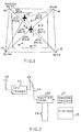
- FIG. 1 shows an aircraft test range whose boundaries form a quadrilateral, the corners of the quadrilateral include ground receive stations 15, 16, 17 and 18, respectively.
- Ground receive station 15 is a master ground receive station which collects data from the other ground receive stations by, for example, a two-way communications link.
- the aircraft test range also includes several ground radar simulating sources 8. As shown in FIG. 1, aircraft 11 and 12 fly against the radar simulating sources to practice evasive maneuvers.
- on board transponder equipment such as, for example, conventional IFF transponders
- squitter transmitters also located on board aircraft 11 and 12.
- the interrogated IFF transponder transmits signals comprising altitude and identification information for the aircraft.
- each of ground receive stations 16-18 includes a local clock which is synchronized with a clock at master ground receive station 15.
- the clocks are used to determine the time of arrival of the transponder signals at ground receive stations 15-18.
- the time of arrival information obtained at receive ground stations 16-18 are transmitted to master ground receive station 15 via the two-way communication links.
- the time of arrival of a signal from an aircraft at a minimum of three (3) ground receive stations can be used to determine the location of the aircraft in longitude and latitude.
- master ground receive station 15 includes a computer which builds a table of time of arrival measurements for each of ground receive stations 15-18 as an aircraft flies through the aircraft test range. Master ground receive station 15 uses this information to determine the aircraft position when it is over the test range. Since the on board IFF transponder transmits an altitude measurement as part of its reply to the interrogation pulse from the squitter transmitter as well as the aircraft identity, the longitude, latitude, and the altitude of the aircraft are available for use in assessing the training exercise.
- the squitter transmitter which interrogates the IFF transponder on the aircraft may interrogate the IFF transponder at periodic intervals and may be fastened to an aircraft strut or weapon holder by well known conventional means.
- FIG. 2 shows the equipment carried by an aircraft for emitting standard IFF signals in accordance with the present invention.
- Random trigger 21 applies an output to squitter transmitter 22 on a random basis.
- squitter transmitter 22 produces standard interrogation pulses such as those shown in FIG. 3A, on a random basis, which interrogation pulses are applied as input to IFF transponder 27.
- squitter transmitter 22 includes antenna 23 for radiating to antenna 26 of IFF transponder 27. Squitter transmitter 22 and random trigger 21 are located on board the aircraft to provide reliable interrogation of IFF transponder 27 and to receive power from the aircraft as described in the '315 patent.
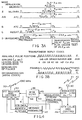
- FIG. 3A shows standard IFF transponder interrogation pulses that are well known to those of ordinary skill in the art and FIG. 3B shows standard transponder reply codes that are also well known to those of ordinary skill in the art.
- squitter transmitter 22 whenever squitter transmitter 22 emits mode A interrogation pulses shown in FIG. 3A, IFF transponder 27 will emit a reply signal which indicates the identity of the aircraft. Further, whenever squitter transmitter 22 emits mode C interrogation pulses shown in FIG. 3A, IFF transponder 27 will emit a reply signal which indicates the altitude of the aircraft. As disclosed in the '315 patent, squitter transmitter 22 is configured to emit mode C interrogation pulses 125 microseconds after having emitted the mode A interrogation pulses.
- ground receive stations 15-18 collect and correlate the emitted identity information from mode A interrogation and altitude information from mode C interrogation and the data is received in a constant 125 microsecond interval, enabling the ground receive stations to correlate the aircraft identity with its altitude.
- the methods and apparatus disclosed in the '315 patent can be improved upon by making the following changes.
- the spacing interval between mode A and mode C interrogation pulses is assigned to different values.
- the improvement that occurs in assigning a different value for the spacing interval between mode A and mode C interrogation pulses is the ability to use the spacing interval to provide additional identification capabilities for aircraft as well as other vehicles.
- ground vehicles could be assigned a spacing interval of 165 microseconds and aircraft could be assigned a spacing interval of 175 microseconds.
- the spacing interval could be set to a unique value and the paired transmissions (replies to mode A and mode C interrogation pulses) can be used to provide 24 bits of identification information rather than the 12 bits of identification information and 12 bits of altitude information emitted in response to the mode A and mode C interrogation.
- the average rate of the randomized transmission can be set to serve the group of vehicles identified by the particular spacing interval chosen.
- squitter transmitter 22 may include a disable switch 22 connected to squitter transmitter 22.
- Disable switch 24 is enabled once the aircraft has returned to the ground to disable squittering of IFF transponder 27 until another flight commences.
- Switch 24 may be connected to the landing gear of the aircraft and operated whenever the aircraft is on the ground.
- squitter transmitter 22 may be keyed at a rate proportional to a signal from an accelerometer sensor mounted on the aircraft, or with package 25. The average rate of interrogation pulses may increase as the aircraft experiences changes in flight path.
- the ground receive stations can decode the rate of received replies and derive a signal representing changes in aircraft flight path.
- the advantage of using sensor 25 is in obtaining useful position information that can be used to position ground radar or ground based tracking systems.
- the interrogation pulse rate may be changed linearly with increases in acceleration --the accelerometer can be implemented to sense any of three directions of movement, lateral, pitch, or yaw (lateral motion sensing being preferred). If the interrogation rate occurs at a nominal periodic rate of 50,000 microseconds, the accelerometer signal can increase this rate linearly. The ground receive stations can decode this change in the nominal periodic rate to derive information relating to the aircraft flight path changes. Additionally, the change in interrogation rate in response to acceleration will increase the total number of aircraft that can be simultaneously tracked because some percentage of the aircraft are in a high acceleration mode while most aircraft are in a normal G condition.
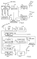
- FIG. 4 A block diagram of remote ground receive stations 16-18 is shown in FIG. 4.
- a ground receive station includes wide band data link transmit/receive station 31 connected to microwave antenna 30 which is positioned to communicate with master ground receive station 15.
- the wide band data link enables synchronization of local clocks 36 at each of remote ground receive stations 16-18 with a master clock at master ground receive station 15. Additionally, the recovered reply data from the IFF transponders and time of arrival information is transmitted back to master ground receive station 15 over the wide band data link.
- the wide band data link is shown to be a wide band microwave data link, those of ordinary skill in the art understand that the present invention is not limited to such an embodiment and that, in accordance with the present invention, the wide band data link could also be embodied as a fiber distributed data interface, a token ring data highway, and so forth.
- IFF transponder 27 Reply signals emitted by IFF transponder 27 are received by antenna 33 at the conventional IFF reply frequency of 1090 MHz.
- IFF receiver and decoder 34 provide for three different quantities of data.
- the conventional identity and altitude data transmitted as part of the mode interrogation of IFF transponder 27 is decoded and the altitude data is supplied to output port 40.
- the time of arrival of the altitude or identity information is determined for each transmission of the transponder reply and the time of arrival data appears at output port 38.
- the time of arrival data is the time noted by IFF receiver 34 when the framing pulses of a reply are received.
- a counter within IFF receiver 34 which counter is under control of real time clock 36, notes the occurrence of each pulse event received and is cleared following the successful decode of both identity and altitude information.
- a time of arrival for the pulse train may be computed based on a running average of framing pulse arrivals or on the arrival of any of the identity or altitude data, as selected by the system designer. Further, the time of arrival between the replies to the mode A and mode C interrogations are determined and converted to an additional piece of identity information by, for example, comparison to information stored in a table.
- output port 41 provides a signal which represents the average periodic rate of time of arrival of the IFF reply and corresponds to the signal produced by an accelerometer on the aircraft. This signal may be used to obtain accurate position change information for the aircraft.
- Message assembler 47 composes the real time arrival data, identity data and altitude data, and if available, the decoded accelerometer signal, into a message for modulating on the carrier signal of the wide band communication link.
- the wide band communication link station 31 will receive this modulation stream and transmit it to master ground receive station 15.
- the real time clock calibration and control network 49 is used during a calibration interval to receive clock data from the wide band data link, decode the same and provide frequency/phase control signal 43 to real time clock 36, which frequency/phase control signal is the result of comparing the actual time of real clock 36 via output port 42 with a received real time from master ground receive station 15.
- embodiments of the present invention also can utilize other methods of calibrating clocks such as using a calibration transponder described in the '315 patent, which description is also incorporated by reference herein.
- FIG. 5 shows master ground receive station 15.
- IFF receiver 68 connected to IFF antenna 71 receives time of arrival data, and identity and altitude information from transponder replies.
- IFF receiver and decoder 68 and message assembler 69 operate in the same manner described above with respect to IFF receiver and decoder 34 and message assembler 47 shown in FIG. 4.
- Message assembler 69 arranges the message in a format which can be delivered to central processor 66. Similar messages are received from the remote ground receive stations 16-18 via individual data links.
- a wide band data link comprising transmit/receive station 61 is used to communicate with the first remote ground receive station and additional data link stations 63 communicate with the remaining remote ground receive stations.
- Central processor 66 collects an assembled data package from each of the remote ground receive stations. If the squitter transmitter interrogation rate is varied in accordance with a sensor signal, this information is provided as well.
- Central processor 66 is a general purpose digital computer which includes a table for each ground receive station, storing the most recent packet of received position and identity data received from each ground receive station. Thus, four tables are built within central processor 66 which contain the identity and corresponding altitude and time of arrival data for each aircraft in the test range. These tables maintain time of arrival data for more than one aircraft since each time of arrival is correlated with each aircraft identity.
- the identity of an aircraft is determined as a combination of IFF transponder identification emitted in reply to the interrogation pulses from the on board squitter transmitters and the spacing between the time of arrival of the IFF transponder reply to mode A and mode C interrogation pulses from the on board squitter transmitter.
- latitude and longitude may be computed from time of arrival data received at three ground receive stations.
- the fourth time of arrival data can be used to permit a series of calculations to be performed among combinations of three ground receive stations. Any errors in data can be discarded in favor of the three most correlated calculations for longitude and latitude position determination. Reporting of the position coordinates for aircraft in the test range can be sent by telephone link or displayed locally in any convenient manner.
- FIG. 6 shows a block diagram of further detail of a ground receive station.
- Each of the ground receive stations have local clocks 36 calibrated so that the time of arrival of transponder replies will be loaded in a corresponding register 47c at each station.
- This time of arrival data may be typically as much as 20 bits wide and include the entire pair of replies, altitude and identity. The time of arrival may be measured against any of the reply bits which are in the register 47c.
- the identity in register 47b includes the 12 bits from the IFF transponder reply as well as, for example, 4 bits determined by the spacing interval between the mode A and mode C interrogation.
- each of the ground receive stations requires only that the clocks at each receive station be synchronized.
- RTR master clock 67 in master ground receive station 15, shown in FIG. 5, can be transmitted to each of remote ground receive stations 16-18 over data links represented by transmit/receive stations 61 through 63. It is well known to those of ordinary skill in the art that to achieve accurate synchronism between remotely located clocks and master clock 67, calibration is required at each ground receive station to compensate path delay experienced by transmission of clock information from the master station to each of the ground receive stations. As stated above, such a calibration method and apparatus are described in the '315 patent. As further described in the '315 patent, an alternative method for calibrating the clocks in the remote ground receive stations utilizes a calibration transponder.
- Calibration transponder 9 is shown in FIG. 1 to be located within the test range.
- Calibration transponder is operated in a squitter mode, preferably at a lower squitter rate such as 1 transmission per second, emitting both an identity and altitude transmission, which transmissions are received by each of the ground receive stations 15-18.
- the distances between each of the ground receive stations and transponder 9 is known precisely.
- Each receive station notes the time of arrival using its internal receive clock just as it does when tracking aircraft through the test range.
- the time of arrival for these transmissions is reported to the master ground receive station and, since the distances from the transponder to each of the ground receive stations is known, an expected time of arrival for each of these distances is also known.
- the computer at the master ground receive station compares the expected time of arrival data with actual time of arrival data. Then, the computer at the master ground receive station can compute clock offset corrections for each ground receive station real time clock, and modify subsequent time of arrival information received from a target aircraft.
- This technique for calibrating the receive clocks is advantageous for several reasons: First, this calibration technique does not require an outgoing data link from the master ground receive station to each of the other ground receive stations. Second, this calibration technique permits verification of the tracking system operation before in-flight measurements begin. Third, one does not need to utilize a wideband data link to send data from the remote ground receive stations to the master. Instead, one can utilize a low speed data link such as, for example, a telephone link.
- An alternative embodiment of the present invention is useful in aircraft such as many military aircraft which have both IFF transponder and TACAN navigation equipment.
- a cross-link circuit may be used so that TACAN interrogations emitted on the aircraft are used to interrogate the IFF transponder on the aircraft.
- crystal detector 71 is connected to small receiving antenna 70.
- TACAN interrogation pulses which are RF pulses of several hundred watt magnitude are received by detector 71.
- the resulting pulse from detector 71 is decoded in decoder 72.
- a delayed pulse provided by delay circuit 73 is used to initiate a mode C interrogation from a transmitter 75.
- mode C interrogation can be perfected in response to the TACAN pulse and is supplied through antenna 77 as in the previous embodiment to interrogate the IFF transponder.
- Using the TACAN interrogation pulses to trigger a mode C interrogation provides an ability to identify transponder replies to the mode C interrogation without requiring a mode 1, 2, or 3 interrogation of the IFF transmitter.
- further identification information is provided by varying the spacing interval between the TACAN signal and the mode C interrogation by varying the delay produced by delay 73.
- the remote ground receive stations can include a TACAN receiver 79 as well as an IFF receiver 82.
- the particular channel of the TACAN receiver which receives a TACAN inquiry correlated with an IFF reply received at the ground receive station can be used to identify the aircraft. Since the TACAN inquiry initiates the IFF reply, they are time correlated, permitting the remote receiving site to correlate altitude with identity.
- TACAN antenna 78 supplies each received TACAN pulse to TACAN receiver 79.
- the aircraft is identified at a first level in accordance with a preassigned TACAN frequency. Further, the time of arrival of the TACAN pulse and the IFF transponder reply are used to add to the identification information provide by the TACAN frequency in the manner described above.
- IFF antenna 81 at the ground receive station is connected to the IFF receiver and decoder.
- the altitude and time of arrival information is once again compiled by message assembler 87.
- Real time clock 84 is calibrated with calibration and control circuitry 88 as previously described.
- a wide band data link is provided by data station 85 and calibration and modulated position data is transmitted via wide band data link station 85 back to the master ground receive.
Landscapes
- Engineering & Computer Science (AREA)
- Radar, Positioning & Navigation (AREA)
- Remote Sensing (AREA)
- Physics & Mathematics (AREA)
- General Physics & Mathematics (AREA)
- Computer Networks & Wireless Communication (AREA)
- Radar Systems Or Details Thereof (AREA)
- Position Fixing By Use Of Radio Waves (AREA)
Applications Claiming Priority (2)
| Application Number | Priority Date | Filing Date | Title |
|---|---|---|---|
| US153257 | 1988-02-08 | ||
| US08/153,257 US5424746A (en) | 1993-11-16 | 1993-11-16 | Method and system for monitoring vehicles |
Publications (3)
| Publication Number | Publication Date |
|---|---|
| EP0653643A2 true EP0653643A2 (fr) | 1995-05-17 |
| EP0653643A3 EP0653643A3 (fr) | 1996-07-17 |
| EP0653643B1 EP0653643B1 (fr) | 2000-01-12 |
Family
ID=22546421
Family Applications (1)
| Application Number | Title | Priority Date | Filing Date |
|---|---|---|---|
| EP94117037A Expired - Lifetime EP0653643B1 (fr) | 1993-11-16 | 1994-10-27 | Procédé et système pour surveiller des véhicules |
Country Status (4)
| Country | Link |
|---|---|
| US (1) | US5424746A (fr) |
| EP (1) | EP0653643B1 (fr) |
| CA (1) | CA2117989A1 (fr) |
| DE (1) | DE69422593T2 (fr) |
Cited By (3)
| Publication number | Priority date | Publication date | Assignee | Title |
|---|---|---|---|---|
| DE10029456A1 (de) * | 2000-03-06 | 2001-09-20 | Cairos Technologies Ag | Verfahren zur Eichung eines Sensorsystems |
| FR2844951A1 (fr) * | 2002-09-24 | 2004-03-26 | Thales Sa | Procede et dispositif d'identification non selective pour groupe de combat ou d'intervention. |
| WO2010142768A1 (fr) * | 2009-06-12 | 2010-12-16 | Thales Deutschland Holding Gmbh | Système de radar secondaire de surveillance pour contrôle du trafic aérien |
Families Citing this family (32)
| Publication number | Priority date | Publication date | Assignee | Title |
|---|---|---|---|---|
| US6324489B1 (en) | 1999-10-29 | 2001-11-27 | Safegate International Ab | Aircraft identification and docking guidance systems |
| BR9408629A (pt) * | 1994-10-14 | 1998-12-01 | Airport Tech Scandinavia | Sistema e processo para verificar a forma de um objeto detectado e sistema para rastrear um objeto |
| US6812824B1 (en) | 1996-10-17 | 2004-11-02 | Rf Technologies, Inc. | Method and apparatus combining a tracking system and a wireless communication system |
| KR20000049066A (ko) * | 1996-10-17 | 2000-07-25 | 핀포인트 코포레이션 | 물품검색 시스템 |
| US6076099A (en) * | 1997-09-09 | 2000-06-13 | Chen; Thomas C. H. | Method for configurable intelligent-agent-based wireless communication system |
| US7612716B2 (en) | 1999-03-05 | 2009-11-03 | Era Systems Corporation | Correlation of flight track data with other data sources |
| US8203486B1 (en) | 1999-03-05 | 2012-06-19 | Omnipol A.S. | Transmitter independent techniques to extend the performance of passive coherent location |
| US7570214B2 (en) | 1999-03-05 | 2009-08-04 | Era Systems, Inc. | Method and apparatus for ADS-B validation, active and passive multilateration, and elliptical surviellance |
| US7739167B2 (en) | 1999-03-05 | 2010-06-15 | Era Systems Corporation | Automated management of airport revenues |
| US8446321B2 (en) | 1999-03-05 | 2013-05-21 | Omnipol A.S. | Deployable intelligence and tracking system for homeland security and search and rescue |
| US7782256B2 (en) | 1999-03-05 | 2010-08-24 | Era Systems Corporation | Enhanced passive coherent location techniques to track and identify UAVs, UCAVs, MAVs, and other objects |
| US7777675B2 (en) | 1999-03-05 | 2010-08-17 | Era Systems Corporation | Deployable passive broadband aircraft tracking |
| US7908077B2 (en) | 2003-06-10 | 2011-03-15 | Itt Manufacturing Enterprises, Inc. | Land use compatibility planning software |
| US7667647B2 (en) | 1999-03-05 | 2010-02-23 | Era Systems Corporation | Extension of aircraft tracking and positive identification from movement areas into non-movement areas |
| US7889133B2 (en) | 1999-03-05 | 2011-02-15 | Itt Manufacturing Enterprises, Inc. | Multilateration enhancements for noise and operations management |
| US6865612B2 (en) * | 2000-02-19 | 2005-03-08 | International Business Machines Corporation | Method and apparatus to provide high precision packet traversal time statistics in a heterogeneous network |
| US6946989B2 (en) * | 2000-03-01 | 2005-09-20 | Geir Monsen Vavik | Transponder, including transponder system |
| NL1015964C2 (nl) * | 2000-08-18 | 2002-02-19 | Amb I T Holding B V | Meetstation voor een stelsel voor positiebepaling van een transponder. |
| US6563432B1 (en) | 2001-01-12 | 2003-05-13 | Safegate International Ab | Aircraft docking system and method with automatic checking of apron and detection of fog or snow |
| US7039978B2 (en) * | 2002-02-01 | 2006-05-09 | Dew Engineering And Development Limited | Flexible over the wing passenger loading bridge |
| US6526615B1 (en) * | 2002-02-01 | 2003-03-04 | Dew Engineering And Development Limited | Flexible over the wing passenger loading bridge |
| US7231274B2 (en) * | 2005-05-09 | 2007-06-12 | Lear Corporation | Method of programming a tire monitoring system |
| GB0607864D0 (en) * | 2006-04-20 | 2006-05-31 | Ubisense Ltd | Calibration Of A Location System |
| US7965227B2 (en) | 2006-05-08 | 2011-06-21 | Era Systems, Inc. | Aircraft tracking using low cost tagging as a discriminator |
| EP2136221B1 (fr) * | 2008-06-18 | 2013-10-09 | Saab Ab | Vérification de validité des informations de position de véhicule transmises par des liens de données synchronisées |
| CN102884440B (zh) * | 2010-03-17 | 2016-04-13 | 霍尼韦尔国际公司 | 用于短基线、低成本地确定空中飞行器位置的系统和方法 |
| US20140104096A1 (en) * | 2011-02-21 | 2014-04-17 | Oto Melara Spa | Electronic system for the identification and neutralization of menaces in a predefined area |
| RU2499999C2 (ru) * | 2012-02-29 | 2013-11-27 | Анатолий Леонидович Сартаков | Способ и система определения местоположения передатчика сигнала по времени прибытия сигнала |
| GB2550854B (en) | 2016-05-25 | 2019-06-26 | Ge Aviat Systems Ltd | Aircraft time synchronization system |
| US12230142B2 (en) * | 2022-03-01 | 2025-02-18 | Aviation Capital Partners, Llc | Status reporting system for aircraft |
| US20230281726A1 (en) * | 2022-03-01 | 2023-09-07 | Scott Beale | Status reporting system for aircraft |
| US20260029523A1 (en) * | 2024-07-25 | 2026-01-29 | Richard Mitchell | Distributed radar system |
Family Cites Families (18)
| Publication number | Priority date | Publication date | Assignee | Title |
|---|---|---|---|---|
| US3905035A (en) * | 1966-03-31 | 1975-09-09 | Us Navy | Electronic countermeasure system |
| BE757418A (fr) * | 1969-08-08 | 1971-04-13 | Int Standard Electric Corp | Transpondeur a taux d'emission eleve |
| US3950753A (en) * | 1973-12-13 | 1976-04-13 | Chisholm John P | Stepped cardioid bearing system |
| US3969725A (en) * | 1974-06-12 | 1976-07-13 | The United States Of America As Represented By The Secretary Of Transportation | Distance measuring equipment |
| US4010465A (en) * | 1975-04-04 | 1977-03-01 | International Telephone And Telegraph Corporation | Channel encoding for distance measurement equipment |
| US3997898A (en) * | 1975-05-05 | 1976-12-14 | International Telephone And Telegraph Corporation | Channeling method and apparatus |
| US4128839A (en) * | 1977-06-28 | 1978-12-05 | The Bendix Corporation | Means for accumulating aircraft position data for a beacon based collision avoidance system and other purposes |
| US4143376A (en) * | 1977-10-11 | 1979-03-06 | International Telephone & Telegraph Corp. | Method for sampling tacan signal envelope |
| US4191958A (en) * | 1978-04-03 | 1980-03-04 | H & L Co. | Radiolocation with respect to an Own station, using Omega signals or the like |
| US4385300A (en) * | 1980-12-22 | 1983-05-24 | The Singer Company | Digital TACAN processor |
| US4688046A (en) * | 1982-09-13 | 1987-08-18 | Isc Cardion Electronics, Inc. | ADF bearing and location for use with ASR and ASDE displays |
| US4532516A (en) * | 1982-10-18 | 1985-07-30 | The Singer Company | Calibrator for distance measuring equipment |
| FR2545297A1 (fr) * | 1983-04-26 | 1984-11-02 | Thomson Csf | Dispositif de retard et son utilisation dans le dispositif de decodage d'un equipement de mesure de distance |
| US4680587A (en) * | 1985-08-14 | 1987-07-14 | Sundstrand Data Control, Inc. | Instrument landing system |
| US4782450A (en) * | 1985-08-27 | 1988-11-01 | Bennett Flax | Method and apparatus for passive airborne collision avoidance and navigation |
| CA2009344C (fr) * | 1989-02-10 | 1994-12-06 | Carl E. Schwab | Systeme precis de surveillance de la position d'un aeronef au cours d'exercices d'instruction |
| US5144315A (en) * | 1989-02-10 | 1992-09-01 | Cardion, Inc. | System for accurately monitoring aircraft position during training exercises |
| US5262784A (en) * | 1992-06-15 | 1993-11-16 | Cardion, Inc. | System for monitoring aircraft position |
-
1993
- 1993-11-16 US US08/153,257 patent/US5424746A/en not_active Expired - Lifetime
-
1994
- 1994-10-12 CA CA002117989A patent/CA2117989A1/fr not_active Abandoned
- 1994-10-27 EP EP94117037A patent/EP0653643B1/fr not_active Expired - Lifetime
- 1994-10-27 DE DE69422593T patent/DE69422593T2/de not_active Expired - Lifetime
Cited By (7)
| Publication number | Priority date | Publication date | Assignee | Title |
|---|---|---|---|---|
| DE10029456A1 (de) * | 2000-03-06 | 2001-09-20 | Cairos Technologies Ag | Verfahren zur Eichung eines Sensorsystems |
| FR2844951A1 (fr) * | 2002-09-24 | 2004-03-26 | Thales Sa | Procede et dispositif d'identification non selective pour groupe de combat ou d'intervention. |
| EP1404137A1 (fr) * | 2002-09-24 | 2004-03-31 | Thales | Procédé et dispositif d'identification non sélective pour groupe de combat ou d'intervention |
| WO2010142768A1 (fr) * | 2009-06-12 | 2010-12-16 | Thales Deutschland Holding Gmbh | Système de radar secondaire de surveillance pour contrôle du trafic aérien |
| EP2267476A1 (fr) * | 2009-06-12 | 2010-12-29 | Thales Deutschland Holding GmbH | Système de radar de surveillance secondaire pour le contrôle du trafic aérien |
| CN102483456A (zh) * | 2009-06-12 | 2012-05-30 | 泰雷兹德国有限公司 | 用于空中交通管制的二次监视雷达系统 |
| US9689980B2 (en) | 2009-06-12 | 2017-06-27 | Thales Deutschland Gmbh | Secondary surveillance radar system for air traffic control |
Also Published As
| Publication number | Publication date |
|---|---|
| DE69422593T2 (de) | 2000-06-08 |
| CA2117989A1 (fr) | 1995-05-17 |
| EP0653643B1 (fr) | 2000-01-12 |
| EP0653643A3 (fr) | 1996-07-17 |
| DE69422593D1 (de) | 2000-02-17 |
| US5424746A (en) | 1995-06-13 |
Similar Documents
| Publication | Publication Date | Title |
|---|---|---|
| EP0653643B1 (fr) | Procédé et système pour surveiller des véhicules | |
| US5144315A (en) | System for accurately monitoring aircraft position during training exercises | |
| CA2009344C (fr) | Systeme precis de surveillance de la position d'un aeronef au cours d'exercices d'instruction | |
| US6094169A (en) | Multilateration auto-calibration and position error correction | |
| US4729737A (en) | Airborne laser/electronic warfare training system | |
| CN102483456B (zh) | 用于空中交通管制的二次监视雷达系统 | |
| US5262784A (en) | System for monitoring aircraft position | |
| US4115771A (en) | Passive ATCRBS using signals of remote SSR | |
| CA1267206A (fr) | Systeme d'atterrissage aux instruments | |
| CA1079838A (fr) | Systeme de prevention de collisions | |
| US20070120738A1 (en) | Systems and methods for TDOA/FDOA location | |
| US6424290B1 (en) | Narrowband passive differential tracking system (U) | |
| CN109655845A (zh) | 无人机定位导航欺骗及其控制方法 | |
| Garcia et al. | Test for success: Next generation aircraft identification system RF simulation | |
| US6114990A (en) | Device for real time simulation | |
| AU1593188A (en) | Multi-mode microwave landing system | |
| US10942241B2 (en) | System for indoor and outdoor position measurement | |
| AU600740B2 (en) | Advanced instrument landing system | |
| EP4495635A1 (fr) | Détection du spoofing dans un système global de navigation par satellite (gnss) à l'aide d'une distance oblique | |
| Sadowski et al. | Asynchronous WAM with irregular pulse repetition | |
| Richardson et al. | Formation flight system design concept | |
| US3699570A (en) | Tacan ground station track and display system | |
| RU2830184C1 (ru) | Способ и устройство контроля достоверности данных системы автоматического зависимого наблюдения (варианты) | |
| US3560991A (en) | Station keeping,collision avoidance and position fixing system | |
| RU2785810C1 (ru) | Способ наблюдения за аэродромным движением и устройство для его осуществления |
Legal Events
| Date | Code | Title | Description |
|---|---|---|---|
| PUAI | Public reference made under article 153(3) epc to a published international application that has entered the european phase |
Free format text: ORIGINAL CODE: 0009012 |
|
| AK | Designated contracting states |
Kind code of ref document: A2 Designated state(s): DE FR GB IT SE |
|
| PUAL | Search report despatched |
Free format text: ORIGINAL CODE: 0009013 |
|
| AK | Designated contracting states |
Kind code of ref document: A3 Designated state(s): DE FR GB IT SE |
|
| 17P | Request for examination filed |
Effective date: 19961204 |
|
| RAP1 | Party data changed (applicant data changed or rights of an application transferred) |
Owner name: CARDION NEWCO, INC. |
|
| GRAG | Despatch of communication of intention to grant |
Free format text: ORIGINAL CODE: EPIDOS AGRA |
|
| 17Q | First examination report despatched |
Effective date: 19990407 |
|
| GRAG | Despatch of communication of intention to grant |
Free format text: ORIGINAL CODE: EPIDOS AGRA |
|
| GRAH | Despatch of communication of intention to grant a patent |
Free format text: ORIGINAL CODE: EPIDOS IGRA |
|
| GRAH | Despatch of communication of intention to grant a patent |
Free format text: ORIGINAL CODE: EPIDOS IGRA |
|
| GRAA | (expected) grant |
Free format text: ORIGINAL CODE: 0009210 |
|
| AK | Designated contracting states |
Kind code of ref document: B1 Designated state(s): DE FR GB IT SE |
|
| ITF | It: translation for a ep patent filed | ||
| REF | Corresponds to: |
Ref document number: 69422593 Country of ref document: DE Date of ref document: 20000217 |
|
| ET | Fr: translation filed | ||
| PLBE | No opposition filed within time limit |
Free format text: ORIGINAL CODE: 0009261 |
|
| STAA | Information on the status of an ep patent application or granted ep patent |
Free format text: STATUS: NO OPPOSITION FILED WITHIN TIME LIMIT |
|
| 26N | No opposition filed | ||
| PGFP | Annual fee paid to national office [announced via postgrant information from national office to epo] |
Ref country code: SE Payment date: 20010920 Year of fee payment: 8 |
|
| REG | Reference to a national code |
Ref country code: GB Ref legal event code: IF02 |
|
| PG25 | Lapsed in a contracting state [announced via postgrant information from national office to epo] |
Ref country code: SE Free format text: LAPSE BECAUSE OF NON-PAYMENT OF DUE FEES Effective date: 20021028 |
|
| EUG | Se: european patent has lapsed | ||
| PGFP | Annual fee paid to national office [announced via postgrant information from national office to epo] |
Ref country code: DE Payment date: 20101020 Year of fee payment: 17 |
|
| PGFP | Annual fee paid to national office [announced via postgrant information from national office to epo] |
Ref country code: IT Payment date: 20101022 Year of fee payment: 17 Ref country code: GB Payment date: 20101027 Year of fee payment: 17 |
|
| PGFP | Annual fee paid to national office [announced via postgrant information from national office to epo] |
Ref country code: FR Payment date: 20111103 Year of fee payment: 18 |
|
| GBPC | Gb: european patent ceased through non-payment of renewal fee |
Effective date: 20121027 |
|
| REG | Reference to a national code |
Ref country code: FR Ref legal event code: ST Effective date: 20130628 |
|
| PG25 | Lapsed in a contracting state [announced via postgrant information from national office to epo] |
Ref country code: DE Free format text: LAPSE BECAUSE OF NON-PAYMENT OF DUE FEES Effective date: 20130501 Ref country code: GB Free format text: LAPSE BECAUSE OF NON-PAYMENT OF DUE FEES Effective date: 20121027 |
|
| REG | Reference to a national code |
Ref country code: DE Ref legal event code: R119 Ref document number: 69422593 Country of ref document: DE Effective date: 20130501 |
|
| PG25 | Lapsed in a contracting state [announced via postgrant information from national office to epo] |
Ref country code: IT Free format text: LAPSE BECAUSE OF NON-PAYMENT OF DUE FEES Effective date: 20121027 Ref country code: FR Free format text: LAPSE BECAUSE OF NON-PAYMENT OF DUE FEES Effective date: 20121031 |