EP0653692B1 - Procédé et appareil de commande de la puissance d'une source d'alimentation par batterie - Google Patents
Procédé et appareil de commande de la puissance d'une source d'alimentation par batterie Download PDFInfo
- Publication number
- EP0653692B1 EP0653692B1 EP94308262A EP94308262A EP0653692B1 EP 0653692 B1 EP0653692 B1 EP 0653692B1 EP 94308262 A EP94308262 A EP 94308262A EP 94308262 A EP94308262 A EP 94308262A EP 0653692 B1 EP0653692 B1 EP 0653692B1
- Authority
- EP
- European Patent Office
- Prior art keywords
- power
- operating point
- voltage
- input voltage
- value
- Prior art date
- Legal status (The legal status is an assumption and is not a legal conclusion. Google has not performed a legal analysis and makes no representation as to the accuracy of the status listed.)
- Expired - Lifetime
Links
- 238000000034 method Methods 0.000 title claims description 71
- 238000005070 sampling Methods 0.000 claims description 80
- 230000008859 change Effects 0.000 claims description 63
- 230000001105 regulatory effect Effects 0.000 claims description 13
- 230000007423 decrease Effects 0.000 claims description 11
- 230000003247 decreasing effect Effects 0.000 claims description 5
- 238000012887 quadratic function Methods 0.000 claims 3
- 230000001276 controlling effect Effects 0.000 claims 1
- 230000006870 function Effects 0.000 claims 1
- 230000005855 radiation Effects 0.000 description 66
- 238000006243 chemical reaction Methods 0.000 description 39
- 238000001514 detection method Methods 0.000 description 18
- 230000008569 process Effects 0.000 description 14
- 238000006073 displacement reaction Methods 0.000 description 6
- 238000010248 power generation Methods 0.000 description 6
- 238000010586 diagram Methods 0.000 description 5
- 238000004364 calculation method Methods 0.000 description 4
- 238000010276 construction Methods 0.000 description 3
- 238000007796 conventional method Methods 0.000 description 3
- 230000009467 reduction Effects 0.000 description 3
- 239000004065 semiconductor Substances 0.000 description 2
- 229910021417 amorphous silicon Inorganic materials 0.000 description 1
- 230000008033 biological extinction Effects 0.000 description 1
- 150000001875 compounds Chemical class 0.000 description 1
- 229910021419 crystalline silicon Inorganic materials 0.000 description 1
- 238000005485 electric heating Methods 0.000 description 1
- 230000006872 improvement Effects 0.000 description 1
- 239000013081 microcrystal Substances 0.000 description 1
- 229910021421 monocrystalline silicon Inorganic materials 0.000 description 1
- 229910052710 silicon Inorganic materials 0.000 description 1
- 239000010703 silicon Substances 0.000 description 1
Images


Classifications
-
- G—PHYSICS
- G05—CONTROLLING; REGULATING
- G05F—SYSTEMS FOR REGULATING ELECTRIC OR MAGNETIC VARIABLES
- G05F1/00—Automatic systems in which deviations of an electric quantity from one or more predetermined values are detected at the output of the system and fed back to a device within the system to restore the detected quantity to its predetermined value or values, i.e. retroactive systems
- G05F1/66—Regulating electric power
- G05F1/67—Regulating electric power to the maximum power available from a generator, e.g. from solar cell
-
- Y—GENERAL TAGGING OF NEW TECHNOLOGICAL DEVELOPMENTS; GENERAL TAGGING OF CROSS-SECTIONAL TECHNOLOGIES SPANNING OVER SEVERAL SECTIONS OF THE IPC; TECHNICAL SUBJECTS COVERED BY FORMER USPC CROSS-REFERENCE ART COLLECTIONS [XRACs] AND DIGESTS
- Y10—TECHNICAL SUBJECTS COVERED BY FORMER USPC
- Y10S—TECHNICAL SUBJECTS COVERED BY FORMER USPC CROSS-REFERENCE ART COLLECTIONS [XRACs] AND DIGESTS
- Y10S323/00—Electricity: power supply or regulation systems
- Y10S323/906—Solar cell systems
Definitions
- the present invention concerns a method of regulating the power output of a power converter, particularly one connected across a solar battery power source, or the like. It also concerns an apparatus including a controller for regulating the power output of such a power converter.
- a battery power system such as a solar cell, aerogenerator, etc.
- a solar cell When a solar cell is used as a battery power source that is connected to a utility grid, the utility grid acts as a substantially infinite load. Under this condition, it is required to establish a technique that can provide the highest efficiency in the operation of the battery power system as a whole. Not only should the total efficiency of the battery power system be high, but also the total power system including the utility grid should have high efficiency. Thus, it is required to establish a technique to achieve the highest efficiency in the total power system.
- the output power greatly depends on the intensity of solar radiation, temperature, or the voltage at the operating point. Therefore, the load seen from the solar cell system should be adjusted such that the solar cell system can always provide the maximum power.
- One of the techniques known for the above purposes is to change the operating-point voltage or current of a solar cell array, including a plurality of solar cells, and to detect the resultant change in power thereby determining the optimum operating point for the solar cell array to provide the maximum, or nearly maximum, power.
- One of techniques of this kind is disclosed in Japanese Patent No. 63-57807, that is based on the derivative of the power with respect to the voltage.
- Another technique of this kind is the so-called "hill-climbing method" in which the optimum operating point is searched by varying the power in a direction that leads to an increase in the power, as disclosed, for example, in Japanese Patent Laid-Open No. 62-85312 or US-A-4 899 269. These methods are widely used in conventional solar cell systems to control a power conversion apparatus so as to provide the maximum power.
- the decision that the voltage should be decreased will be made judging from the operation point (1) and the open circle.
- the intensity of solar radiation increases during the time period between the sampling times tl and t2
- the increase in power from P1 to P2 will lead to an incorrect decision that the voltage should be increased.
- the correct decision would be that the voltage should be decreased, as can be seen from the voltage operating point (2) lying on the V-P curve at time t2.
- the searching is further done in the direction that leads to a higher operating voltage, and thus the instantaneous output efficiency decreases (the instantaneous output efficiency is defined as the ratio of the output power to the maximum available power at an arbitrary time).
- the output efficiency is defined as the ratio of the output power to the maximum available power during a certain time duration.
- the output voltage increases.
- the output voltage may decrease or may remain at the same value as a result of an incorrect decision.
- an erroneous operation of the power control system leads to an abrupt decrease in the output voltage of the solar cell system, and causes a protection circuit to undesirably shutdown a power conversion apparatus.
- the operation is performed according to the hill-climbing method.
- the power control method based on the derivative of the power with respect to the voltage also has a similar problem.
- the present invention is provided as a remedy.
- the method and apparatus of the present invention are of the type known from Japanese Patent No. 63-57807 and Japanese Patent Laid-Open N. 62-85312, acknowledged hereinbefore, having those features recited in the preamble of claims 1 and 11 attached.
- the method of regulating the power output of a power converter is, in accordance with the present invention, characterised in that:
- a variation in current or power that has occurred during a sampling time interval is estimated from a difference in current or power at the same voltage, and current signals or power values are corrected using the estimated variation in current or power, data lying on a correct I-V curve at an arbitrary given time can be obtained, regardless of variations of parameters such as the intensity of solar radiation, thereby searching the optimum operating point at which the maximum output power is obtained.
- the maximum power can always be extracted from the battery power source, without any instability in operation, regardless of the variation in the intensity of solar radiation.
- sampling operation is required to be done only twice at the same voltage, it is possible to quickly search the optimum operating point with the minimum number of sampling operations. If sampling operations for the same voltage are done first and last in each sampling cycle, the information of the change in the intensity of solar radiation that occurs during a time interval from the start of a sampling cycle to the end of the cycle can be obtained, and therefore more accurate correction can be performed on the data.
- the apparatus of the present invention is characterised in that:
- the invention concerns a memory as defined in claim 21.
- the present invention is based on the finding that in a searching operation for the maximum power of a battery power source, apparent displacement of a characteristic curve, such as a P-I curve or V-I curve, occurs to a rather larger degree during each sampling interval Ts, while the change in the apparent shape of the characteristic curve during this interval Ts is rather small.
- the apparent displacement of the characteristic curve occurs at a substantially constant rate during the sampling interval Ts.
- a good approximation or correction of a characteristic curve at an arbitrary time can be obtained from values sampled at sampling intervals Ts. Power control can be successfully performed on the basis of this corrected characteristic to achieve high efficiency in a total system.
- FIG. 1 illustrates an electric power generating system, using solar energy, based on a power control method of the present invention.
- the DC power-of a solar cell 1 serving as a battery power source, is subjected to power conversion at a power conversion apparatus 2, serving as power conversion means, and is then supplied to a load 3.
- the battery power source 1 can be implemented with a solar cell comprising a semiconductor, such as amorphous silicon, micro-crystal silicon, crystalline silicon, single-crystal silicon, compound semiconductor, or the like.
- a solar cell comprising a semiconductor, such as amorphous silicon, micro-crystal silicon, crystalline silicon, single-crystal silicon, compound semiconductor, or the like.
- a plurality of solar cells are combined in a series-and-parallel form and arranged in an array or string form so that a desired voltage and a desired current are obtained.
- the power conversion means 2 can be implemented by a DC/DC converter constructed with a switching device of the self extinction type such as a power transistor, power MOS FET, IGBT, GTO, etc., or a self excited DC/AC inverter.
- the power flow, input and output voltage, and output frequency are controlled by adjusting the duty factor or the on/off ratio of the gate pulse.
- the load 3 can be an electric heating system, an electric motor, a commercial AC system, etc., or combinations of these loads.
- the load is a commercial AC system
- the solar cell system is called a grid connection solarlight power generation system.
- the power control method of the present invention can be advantageously used to extract the maximum power from the battery power source.
- the output voltage and the output current of the battery power source 1 are sampled using conventional voltage detection means 4 and current detection means 5.
- the voltage signal detected in the form of digital data, is applied to output voltage setting means 6 and control means 7.
- the detected current signal is applied to the output voltage setting means 6.
- the average value is determined from instantaneous values.
- the output voltage setting means 6 determines a target voltage from the voltage signals and current signals that have been detected and stored, and adjusts the duty factor or the on/off ratio so that the output voltage of the solar cell system is maintained at the target voltage.
- the output voltage setting means 6 is implemented by a microcomputer including a CPU, RAM, I/O circuit, etc.
- the control means 7 is the so-called gate driving circuit that generates a PWW pulse to drive the gate according to, for example, the triangular wave comparison method or the instantaneous current tracking control method, whereby the on/off duty factor of the power conversion means 2 is controlled to control the output voltage of the solar cell system.
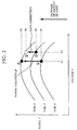
- Figure 2 illustrates voltage-power output characteristics at different times, in which the horizontal axis represent the voltage V, and the vertical axis represents the power P. As can be seen from Figure 2, the change in the apparent shape of the V-P curve is small.
- the variation in the intensity of solar radiation is estimated from the difference between the power obtained at two operating points having the same voltage V1. That is, since the output current or the output power of the solar cell system changes in proportion to the intensity of the solar radiation as long as the output voltage is maintained constant, the difference in power for the same output voltage indicates the change in the intensity of solar radiation that has occurred during the measuring interval.
- the data is corrected using ⁇ P which includes the information representing the change in the intensity of solar radiation.
- the sampling interval Ts is preferably less than 1 sec, and more preferably less than 1/30 sec, so that the intensity of solar radiation can be considered to change at a constant rate during the time interval from t1 to t3 (the interval is assumed to be 1/30 sec in the following discussion).
- the difference between the output power at voltage V1 and the output power at voltage V2 is so small that the changing rate in the apparent displacement of the output power curve, arising from the change in the intensity of solar radiation during a time interval of the order of the sampling interval Ts, can be regarded as constant for both operating points at V1 and V2.
- power P2 at the operating voltage V2 at time t2 can be corrected to power P2', at the operating voltage V2 at time t3, by adding ⁇ P/2 to power P2 wherein ⁇ P/2 corresponds to the power change arising from the change in the intensity of solar radiation that has occurred during the time interval from t2 to t3.
- P2' P2 + ⁇ P/2
- This corrected operating point is denoted by (2)' in Figure 2.
- the power at the operating point (3) is compared with the power at the operating point (2)', and the next searching direction is determined from the result of the above comparison.
- Power P3 at the operating point (3) is greater than power P2' at the operating point (2)'. This means that the maximum power will be obtained at an operating voltage less than the operating voltage V1, which will lead to a decision that the next searching should be done in the direction that results in a reduction in voltage.
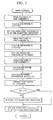
- Figure 3 is a flow chart illustrating this process.
- the power control method of the present embodiment has been applied to a solar cell system including twelve amorphous solar cell modules, produced by USSC Corp. (Product Number: UPM880), wherein these solar cell modules are connected in series.
- This solar cell system has been continuously operated under varying solar radiation, wherein the optimum operating point is searched by varying the voltage in steps of 2 V at sampling intervals of 1/30 sec.
- the solar cell system has shown output efficiency (the ratio of the output power to the maximum available output power) as high as 99.99%.
- the output efficiency was 98.86% under the same conditions.
- the above results indicate that the system having a relatively simple construction according to the present invention can provide improvement in the efficiency by about 1.13%.
- the variation in the intensity of solar radiation is estimated from power values obtained at the same output voltage at different times, thereby obtaining correct data, lying on a correct output characteristic curve, at any given time. Since the searching direction is determined from the data obtained in this way, no erroneous operation occurs in the searching control even if the intensity of solar radiation varies. As a result, the system can extract the maximum power from a solar cell system without instability.
- a solar cell power generation system using a power control method according to the present invention, has a similar construction to that of embodiment 1 shown in Figure 1.
- the power control that will be described below, referring to Figure 4, is based on a different method from that of embodiment 1.
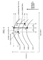
- Figure 4 illustrates voltage-power output characteristics at different times, in which the horizontal axis represent voltage V, and the vertical axis represents power P.
- the data is corrected using ⁇ P which includes the information representing the difference in the intensity of solar radiation.
- the intensity of solar radiation can be considered to change at a constant speed during the time interval from t1 to t4.
- the difference in the output power among the operating points at voltages V1, V2 and V3 is so small that the changing rate in the output power, arising from the change in the intensity of solar radiation during a time interval of the order of the sampling interval Ts, can be regarded as constant for each operating point at V1, V2 and V3.
- power P2 at the operating voltage V2 at time t2 can be corrected to power P2' at the operating voltage V2 at time t4 by adding ⁇ P x 2/3 to power P2 wherein ⁇ P x 2/3 corresponds to the power change arising from the change in the intensity of solar radiation during the time interval from t2 to t4.
- P2' P2 + ⁇ P x (2/3)
- power P3 at the operating voltage V3 at time t3 can be corrected to power P3' at the operating voltage V3 at time t4 by adding ⁇ P x 1/3, to power P3, wherein ⁇ P x 1/3 corresponds to the power change arising from the change in the intensity of solar radiation during the time interval from t3 to t4.
- P3' P3 + ⁇ P x (1/3)
- This corrected operating point is denoted by (3)' in Figure 4.
- the next operating voltage is determined from the data associated with the three operating points (2)', (3)', and (4) as follows.
- the voltage-versus-power output characteristic curve at time t4 is approximated by a quadratic curve on which the operating points (2)', (3)', and (4) lie.
- an arbitrary curve can be approximated well by a quadratic curve for a narrow range.
- a quadratic curve can be uniquely determined from three data points.
- V V1 + ⁇ V/2 x ⁇ (P2' - P3')/ (2 x P4 - P2'- P3') ⁇
- the voltage determined from the above equation is used as a starting voltage in the next searching cycle.
- the power control method of the present embodiment has been applied to a solar cell system including twelve amorphous solar cell modules, produced by USSC Corp. (Product Number: UPM880), wherein these solar cell modules are connected in series.
- This solar cell system has been continuously operated under varying solar radiation, wherein the optimum operating point is searched by varying the voltage in steps of 2 V at sampling intervals of 1/30 sec.
- the solar cell system has shown output efficiency (the ratio of the output power to the maximum available output power) as high as 99.98%.
- the output efficiency was 99.67% under the same conditions.
- the variation in the intensity of solar radiation is estimated from power values obtained at the same output voltage at different times, thereby obtaining correct data lying on a correct output characteristic curve at any given time. Since the starting voltage in the next searching cycle is determined from the data obtained in this way, no erroneous operation due to the change in the intensity of solar radiation occurs in the searching control. As a result, the system can extract the maximum power from a solar cell system without instability.
- a solar cell power generation system using a power control method according to the present invention also has a construction similar to those of embodiments 1 and 2 shown in Figure 1.
- the power control that will be described below, referring to Figure 6, is based on a method different from those of the previous embodiments.
- Figure 6 illustrates voltage-versus-current output characteristics at different times, in which the horizontal axis represent voltage V, and the vertical axis represents current I.
- the operating point is first set to voltage V1. Sampling is performed at time t1 so as to read voltage V1 and current I1 at the operating point (1).
- the data is corrected using ⁇ I which includes the information representing the difference in the intensity of solar radiation.
- the next operating voltage is determined from the data associated with the operating points (2)' and (3) as follows.
- Figure 7 illustrates a typical voltage-versus-power characteristic curve of a solar cell, in which the horizontal axis represent voltage and the vertical axis represents power.
- the gradient of the characteristic curve becomes zero at a point at which the output power has the maximum value.
- the gradient of the characteristic curve is negative.
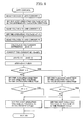
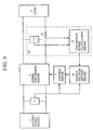
- Figure 8 is a flow chart illustrating this process.
- the power control method of the present embodiment has been applied to a solar cell system, including twelve amorphous solar cell modules produced by USSC Corp. (Product Number: UPM880), wherein these solar cell modules are connected in series.
- This solar cell system has been continuously operated under varying solar radiation, wherein the optimum operating point is searched by varying the voltage in steps of 2 V at sampling intervals of 1/30 sec.
- the solar cell system has shown output efficiency (the ratio of the output power to the maximum available output power) as high as 99.98%.
- the output efficiency was 98.86% under the same conditions.
- the variation in the intensity of solar radiation is estimated from power values obtained at the same output voltage at different times, thereby obtaining correct data lying on a correct output characteristic curve at any given time. Since the starting voltage and the searching direction in the next searching cycle are determined from the data obtained in this way, no erroneous operation due to the change in the intensity of solar radiation occurs in the searching control. As a result, the system can extract the maximum power from a solar cell system without instability.
- DC voltage detection means and DC current means can be used as the voltage detection means for detecting the voltage, and the current detection means for detection the current, respectively, the system can be constructed in a relatively simple fashion.
- FIG. 9 is a schematic diagram illustrating a solar cell power generation system using a power control method according to the present embodiment of the invention.
- similar elements to those in Figure 1 are denoted by similar reference numerals to those in Figure 1.
- the system shown in Figure 9 has the following features. Unlike the system shown in Figure 1, in the power control method of the present embodiment according to the invention, there is no need to detect the output current of the solar cell system. Instead, there is provided power detection means 10 for detecting the output power of a power conversion apparatus 2.
- the power detection means comprises: conversion voltage detection means 11, for detecting the output voltage of the power conversion apparatus 2 (also called the conversion output voltage); conversion current detection means 12, for detecting the output current of the power conversion apparatus 2 (also called the conversion output current); and conversion power calculation means 13 for calculating the output power of the power conversion apparatus 2 (also called the conversion output power) and for outputting the value representing the conversion power.
- conversion power calculation means 13 detects the instantaneous voltage and current at the output of the power conversion apparatus 2, and then calculates the instantaneous power from these values. The output power is then determined by calculating the average value of the instantaneous power.
- Figure 2 illustrates the output characteristics at different times, in which the horizontal axis represent the voltage of the solar cell system, and the vertical axis represents the output power of the power conversion apparatus.
- Figure 2 has been used to illustrate the operation of the system, in which the vertical axis represents the output power of the solar cell.
- the vertical axis represents the output power of the power conversion apparatus.
- the operating point is set to voltage V1. Sampling is performed at time t1 so as to read voltage V1 and current I1 at the operating point (1).
- the data is corrected using ⁇ P that includes the information representing the chage in the intensity of solar radiation.
- the intensity of solar radiation can be considered to change at a constant rate during the time interval from t1 to t3.
- the difference between the output power at voltage V1 and the output power at voltage V2 is so small that the rate of the change in the output power due to the change in the intensity of solar radiation during a time interval of the order of the sampling interval Ts can be regarded as constant for both the operating points at V1 and V2.
- power P2 at the operating voltage V2 at time t2 can be corrected to power P2' at the operating voltage V2 at time t3 by adding ⁇ P/2 to power P2 wherein ⁇ P/2 corresponds to the power change arising from the change in the intensity of solar radiation that has occurred during the time interval from t2 to t3.
- P2' P2 + ⁇ P/2
- This corrected operating point is denoted by (2)' in Figure 3.
- the power at the operating point (3) is compared with the power at the operating point (2)', and the next searching direction is determined from the result of the above comparison.
- Power P3 at the operating point (3) is greater than power P2' at the operating point (2)'. This means that the maximum power will be obtained at an operating voltage less than the operating voltage V1, which will lead to a decision that the next searching should be done in the direction that results in a reduction in voltage.
- Figure 10 is a flow chart illustrating this process.
- the variation in the intensity of solar radiation is estimated from power values obtained at the same output voltage at different times, thereby obtaining correct data lying on a correct output characteristic curve at any given time. Since the searching direction is determined from the data obtained in this way, no erroneous operation occurs in the searching control even if the intensity of solar radiation varies. As a result, the system can extract the maximum power from a solar cell system without instability.
- the power conversion apparatus disposed at the output side of the solar cell system 2 is controlled such that the output power via the power conversion apparatus 2 always has a maximum value.
- FIG 11 is a schematic diagram illustrating a solar electric power generation system in parallel operation with other systems, according to the present embodiment of the invention.
- This system shown in Figure 11 is similar to that of Figure 9.
- the power conversion apparatus 2 and the load 3 are an inverter 14 and an AC system 15, respectively, in this case.
- the voltage setting means 6 receives a current value detected by current detection means 16 instead of receiving detected output power of the power conversion apparatus.
- the current detection means 16 comprises conversion current detection means 12, for detecting an AC output current of the inverter 14 (also called conversion output current), and conversion current calculation means 17, for calculating the average current from instantaneous currents detected by the conversion current detection means 12, thereby outputting the resultant average output current of the inverter 14.
- the output of the inverter 14 is connected to the AC system in parallel operation. Since the voltage of the AC system is nearly constant, the output voltage of the inverter is maintained nearly constant. Therefore, if the power factor of the inverter output is constant (1, for example), the output power of the inverter has a maximum value when the output current of the inverter has a maximum value. Furthermore, the characteristic of the voltage of the solar cell versus the output current of the inverter is similar in shape to the characteristic of the voltage of the solar cell versus the output current of the solar cell. In this embodiment, an approximation algorithm using a quadratic curve is also employed as in embodiment 2.
- Figure 12 illustrates voltage versus current characteristic curves at various times, in which the horizontal axis represent the output voltage V of the solar cell, and the vertical axis represents the output current I of the inverter.
- the operating point is first set to voltage V1. Sampling is performed at time t1 so as to read voltage V1 of the solar cell at the operating point (1) and the output current I1 of the inverter.
- the data is corrected using ⁇ I which includes the information representing the change in the intensity of solar radiation.
- the intensity of solar radiation can be considered to change at a constant rate during the time interval from t1 to t4.
- the difference in output current among voltages V1, V2 and V3 is so small that the rate of the change in the output power, due to the change in the intensity of solar radiation during a time interval of the order of the sampling interval Ts, can be regarded as constant for all operating voltages V1, V2 and V3.
- current I3 at the operating voltage V3 at time t3 can be corrected to current I3' at the operating voltage V3 at time t4 by adding ⁇ I x 1/3 to current I3 wherein ⁇ I x 1/3 corresponds to the current change arising from the change in the intensity of solar radiation during the time interval from t3 to t4.
- I3' I3 + ⁇ I x (1/3)
- This corrected operating point is denoted by (3)' in Figure 12.
- Operating Point (3)': Voltage V3; Current I3'
- the next operating voltage is determined from data associated with three operating points (2)', (3)' and (4) according to the following equation, as in embodiment 2.
- V V1 + ⁇ V/2 x ⁇ (I2' - I3')/(2 x I4 - 12' - I3') ⁇
- the voltage determined from the above equation is used as a starting voltage in the next searching cycle.
- the variation in the intensity of solar radiation is estimated from current values obtained at the same voltage at different times, thereby obtaining correct data lying on a correct output characteristic curve at any given time. Since the starting voltage in the next searching cycle is determined from the data obtained in this way, no erroneous operation due to the change in the intensity of solar radiation occurs in the searching control. As a result, the system can extract the maximum power from a solar cell system without instability.
- the system includes voltage detection means 4, for detecting the voltage of the solar cell, and current detecting means 16, for detecting the average current, via the inverter 14, acting as a power conversion apparatus. There is no need for detecting the output voltage and output power of the inverter. Thus, a system constructed in a simple fashion, according to this embodiment, can always provide the maximum power via the inverter 14.
- the present invention has been described referring to specific embodiments in which a solar cell battery is used as the power source. However, it will be apparent to those skilled in the art that the present invention can also be applied to other various types of power source, having a similar output characteristic, whose output current changes in proportion to a certain variable when the voltage is maintained constant.
- the present invention is very useful in the control of the power.
- the present invention can be advantageously applied to a battery power system that operates in parallel with a commercial power system.
Landscapes
- Engineering & Computer Science (AREA)
- Electromagnetism (AREA)
- Sustainable Development (AREA)
- Sustainable Energy (AREA)
- Power Engineering (AREA)
- Physics & Mathematics (AREA)
- Life Sciences & Earth Sciences (AREA)
- General Physics & Mathematics (AREA)
- Radar, Positioning & Navigation (AREA)
- Automation & Control Theory (AREA)
- Control Of Electrical Variables (AREA)
- Supply And Distribution Of Alternating Current (AREA)
- Charge And Discharge Circuits For Batteries Or The Like (AREA)
Claims (25)
- Procédé pour réguler la puissance de sortie d'un convertisseur de puissance (2 ; 14), dont les entrées sont connectées aux bornes d'une source d'énergie à pile ou batterie (1) et dont les sorties sont connectées aux bornes d'une charge (3 ; 15), ce procédé étant effectué en :ce procédé étant caractérisé en ce que :réglant ledit convertisseur de puissance (2 ; 14) de façon à établir la tension d'entrée du point de fonctionnement (V) de celui-ci à des valeurs de consigne différentes (V1, V2 ; V1, V2, V3) pour des temps d'échantillonnage différents respectifs (t1, t2, ...) d'un cycle d'échantillonnage ;obtenant une valeur d'échantillonnage (P1, P2 ; ... ; I1, I2) d'un paramètre (P ; I) dudit convertisseur de puissance pour chacun desdits temps d'échantillonnage différents dudit cycle d'échantillonnage, ce paramètre étant l'un parmi la puissance d'entrée ou de sortie (P), le courant d'entrée ou de sortie (I) dudit convertisseur de puissance ; etrégulant ledit convertisseur de puissance en remettant à zéro la tension d'entrée de point de fonctionnement (V) de celui-ci, de façon à optimiser, ou, au moins, à augmenter vers l'optimum, la sortie de puissance de celui-ci, en fonction de valeurs d'échantillonnage obtenues dudit paramètre ;
ledit réglage dudit convertisseur de puissance comprend l'établissement de la tension d'entrée de point de fonctionnement (V) à une même valeur de consigne (V1) pour chacun d'une pluralité de temps d'échantillonnage différents (t1, t3 ; t1, t4) dudit cycle d'échantillonnage ; et
en ce que ledit procédé comprend :la correction d'une ou plusieurs valeurs d'échantillonnage (P2 ; P2, P3 ; I2 ; I2, I3) dudit paramètre d'une ampleur de correction respective afin de compenser un changement de la caractéristique de puissance de ladite source d'énergie à pile ou batterie, cette ampleur de correction respective étant dépendante des temps d'échantillonnage correspondants (t2 ; t2, t3) desdites valeurs d'échantillonnage au nombre d'une ou davantage, et étant déterminée à l'aide des valeurs d'échantillonnage (P1, P3 ; P1, P4 ; I1, I3 ; I1, I4) dudit paramètre obtenu pour ladite même valeur de consigne (V1) de la tension d'entrée de point de fonctionnement ; etla régulation dudit convertisseur de puissance en fonction de valeurs d'échantillonnage (P3, P2'; P4, P2', P3', I3, I2' ; I4, I2', I3') qui comprennent lesdites valeurs d'échantillonnage au nombre d'une ou davantage (P2' ; P2', P3' ; I2' ; I2', I3') corrigées desdites ampleurs de correction respectives. - Procédé selon la revendication 1, dans lequel :la tension d'entrée de point de fonctionnement (V) est établie au double seulement de la même valeur de consigne (V1) pour des temps d'échantillonnage respectifs différents (t1, t3 ; t1, t4) dudit cycle d'échantillonnage ; etladite correction comprend le calcul de la vitesse de changement (ΔP/Δt ; Δi/ΔT) dudit paramètre (P, I) à une tension constante (V1) lorsque le rapport de la différence des valeurs d'échantillonnage (P1, P3 ; P1, P4 ; I1, I3 ; I1, I4) obtenues pour la même valeur de consigne (V1) de la tension d'entrée de point de fonctionnement (V) à la différence de ces temps d'échantillonnage respectifs différents (t1, t3 ; t1, t4), et le calcul d'une ampleur de correction respective pour chacune desdites valeurs d'échantillonnage au nombre d'une ou davantage (P2 ; P2, P3 ; I2 ; I2, I3) à l'aide de la vitesse de changement calculée.
- Procédé selon la revendication 2, dans lequel la tension d'entrée de point de fonctionnement (V) est établie à ladite même valeur de consigne (V1) au temps de commencement (t1) et au temps de fin (t3 ; t4) dudit cycle d'échantillonnage.
- Procédé selon la revendication 3, dans lequel lesdites valeurs d'échantillonnage utilisées comme base pour réguler ledit convertisseur de puissance (2 ; 14) comprennent la valeur d'échantillonnage (P3, P4 ; I3 ; I4) obtenue pour le temps de fin (t3 ; t4) dudit cycle d'échantillonnage et desdites valeurs d'échantillonnage au nombre d'une ou davantage (P2' ; P2', P3' ; I2', I2', I3') corrigées desdites ampleurs de correction respectives.
- Procédé selon l'une quelconque des revendications précédentes, dans lequel ledit paramètre est l'un parmi la puissance d'entrée ou la puissance de sortie, et la régulation dudit convertisseur de puissance est effectuée en déterminant, à partir d'une comparaison de deux valeurs d'échantillonnage (P3, P2'), y compris l'une (P2') corrigée de son ampleur de correction respective, la direction du changement de ladite puissance par rapport à la tension d'entrée, et en augmentant ou en diminuant la valeur de la tension d'entrée de point de fonctionnement (V) à partir de sa dernière valeur de consigne (V1) dans la direction d'augmentation de la puissance déterminée à partir de ladite comparaison.
- Procédé selon l'une quelconque des revendications 1 à 4 qui précèdent, dans lequel ledit paramètre est l'un parmi la puissance d'entrée ou la puissance de sortie, et la régulation dudit convertisseur de puissance est effectuée en remettant à zéro la tension d'entrée de point de fonctionnement (V) à une valeur calculée pour correspondre à la puissance maximale (P), cette valeur étant calculée à partir de la solution simultanée d'équations dans lesquelles la puissance est exprimée sous la forme d'une fonction quadratique de la tension d'entrée, à l'aide de trois valeurs d'échantillonnage de puissance (P2', P3', P4) obtenues pour trois valeurs différentes (V2, V3, V1) de la tension d'entrée de point de fonctionnement (V), comprenant deux valeurs d'échantillonnage corrigées (P2', P3'), et les trois valeurs différentes correspondantes (V2, V3, V1) de la tension d'entrée de point de fonctionnement (V).
- Procédé selon l'une quelconque des revendications 1 à 4 qui précèdent, dans lequel la régulation dudit convertisseur de puissance est effectuée en calculant un gradient de puissance (dP/dV) correspondant au dernier réglage (V1) de la tension d'entrée de point de fonctionnement, et en remettant à zéro la tension d'entrée de point de fonctionnement en augmentant, en maintenant ou en diminuant la valeur de consigne (V1) en fonction du fait que la valeur calculée dudit gradient de puissance (dP/dV) est positive, nulle ou négative, le gradient de puissance étant calculé comme étant le rapport de la différence de puissance, correspondant à deux valeurs de consigne différentes de ladite tension d'entrée de point de fonctionnement, à la différence de tension d'entrée de point de fonctionnement.
- Procédé selon la revendication 7, dans lequel ledit paramètre est le courant d'entrée I, et le gradient de puissance (dP/dV) est calculé à l'aide de deux valeurs d'échantillonnage (I3, I2') obtenues pour lesdits deux réglages de valeurs différents (V1, V2), y compris l'un (I2') corrigé de son ampleur de correction respective, et des deux valeurs de consigne différentes.
- Procédé selon l'une quelconque des revendications 1 à 4 qui précèdent, dans lequel ledit convertisseur de puissance est un onduleur (14) pouvant fonctionner de façon à délivrer de l'énergie à une tension de sortie fixe, et ledit paramètre est le courant de sortie.
- Procédé selon la revendication 9, dans lequel la régulation dudit convertisseur de puissance est effectuée en remettant à zéro la tension d'entrée de point de fonctionnement (V) à une valeur calculée pour correspondre à la puissance de sortie maximale (P), cette valeur étant calculée à partir de la solution simultanée d'équations dans lesquelles le courant de sortie est exprimé sous la forme d'une fonction quadratique de la tension d'entrée, à l'aide de trois valeurs d'échantillonnage de courant (I2', I3', I4) obtenues pour trois valeurs différentes (V2, V3, V1) de la tension d'entrée de point de fonctionnement (V), comprenant deux valeurs d'échantillonnage corrigées (I2', I3'), et des trois valeurs différentes correspondantes (V2, V3, V1) de la tension d'entrée de point de fonctionnement (V) .
- Dispositif pour réguler la puissance délivrée à partir d'une source d'énergie (1) à une charge (3, 15) par l'intermédiaire d'un convertisseur de puissance (2, 14), le convertisseur de puissance comportant des moyens pour régler la tension d'entrée de point de fonctionnement (V) développée entre ses entrées, ledit dispositif comprenant :ce dispositif étant caractérisé en ce que :une servocommande (4, 7) pour commander le convertisseur de puissance de façon à régler et à établir la tension d'entrée de point de fonctionnement (V) à une valeur de consigne (V1, V2 ; ...) correspondant à une valeur visée ;des moyens d'échantillonnage (5 ; 4 à 6 ; 10 ; 16) pour obtenir des échantillons de l'un parmi le courant d'entrée ou de sortie, la puissance d'entrée ou de sortie du convertisseur de puissance, correspondant à des temps différents (t1, t2, ...) d'un cycle d'échantillonnage ; etun dispositif de commande (6) pour établir des valeurs visées pour établir la tension d'entrée de point de fonctionnement pour chaque temps différent du cycle d'échantillonnage, et pour déterminer et établir, en fonction des échantillons obtenus dans ledit cycle d'échantillonnage, une valeur visée pour remettre à zéro la tension d'entrée de point de fonctionnement pour optimiser, ou, au moins, augmenter vers l'optimum, la sortie de puissance du convertisseur de puissance ;ledit dispositif de commande est adapté pour établir les valeurs visées pour établir la tension d'entrée de point de fonctionnement à une même valeur (V1) pour une pluralité de temps (t1, t3 ; t1, t4) dudit cycle d'échantillonnage, et à une ou plusieurs valeurs différentes respectives (V2 ; V2, V3) à un ou plusieurs autres temps différents respectifs (t2 ; t2, t3) dudit cycle d'échantillonnage ;ledit dispositif de commande est adapté pour corriger un ou plusieurs desdits échantillons d'une ampleur de correction respective, de façon à compenser un changement de la caractéristique de puissance de la source d'énergie, cette ampleur de correction respective dépendant des temps d'échantillonnage correspondants (t2 ; t2, t3) desdits échantillons au nombre d'un ou davantage, et étant déterminée par ledit dispositif de commande à partir de ceux desdits échantillons (P1, P3 ; P1, P4 ; I1, I3 ; I1, I4) obtenus pour la même valeur de consigne (V1) de la tension d'entrée de point de fonctionnement (V1) ; etledit dispositif de commande est adapté pour déterminer la valeur visée pour remettre à zéro la tension d'entrée en fonction d'échantillons (P3, P2' ; P4, P2', P3' ; I3, I2' ; I4, I2', I3') qui comprennent lesdits échantillons au nombre d'un ou davantage (P2' ; P2', P3' ; I2' ; I2', I3') corrigés desdites ampleurs de correction respectives.
- Dispositif selon la revendication 11, dans lequel lesdits moyens d'échantillonnage servent à obtenir des échantillons de puissance, et comprennent des moyens (5) pour échantillonner le courant et des moyens (6) pour produire lesdits échantillons de puissance en calculant les produits des valeurs de courant échantillonnées et des valeurs respectives de la tension de consigne correspondante.
- Dispositif selon la revendication 12, dans lequel lesdits moyens pour produire lesdits échantillons sont mis en oeuvre dans ledit dispositif de commande (6).
- Dispositif selon la revendication 11, dans lequel :ledit dispositif de commande est agencé de façon à établir lesdites valeurs visées à une même valeur (V1) pour deux temps (t1, t3 ; t1, t4) dudit cycle d'échantillonnage ; etledit dispositif de commande est agencé pour calculer l'ampleur de correction respective en calculant tout d'abord la vitesse de changement à tension constante du courant ou de la puissance représentés par lesdits échantillons (P1 à P3 ; P1 à P4 ; I1 à I3 ; I1 à I4) sous la forme du rapport de la différence des deux valeurs d'échantillonnage des échantillons (P1, P3 ; P1, P4 ; I1, I3, I1, I4) obtenus pour la même tension de consigne, à la différence de leurs temps respectifs différents (t1, t3 ; t1, t4), et en calculant ensuite l'ampleur de correction à l'aide de la vitesse de changement calculée.
- Dispositif selon la revendication 14, dans lequel ledit dispositif de commande est agencé pour établir lesdites valeurs visées à la même valeur (V1) au temps de commencement (t1) et au temps de fin (t3 ; t4) dudit cycle d'échantillonnage.
- Dispositif selon la revendication 15, dans lequel :ledit dispositif de commande est agencé pour corriger les échantillons au nombre d'un ou davantage (P2 ; P2, P3 ; I2 ; I2, I3) obtenus en correspondance avec les temps (t2 ; t2, t3) du cycle d'échantillonnage autres que le temps de commencement (t1) et le temps de fin (t3; t4) etledit dispositif de commande est agencé de façon à déterminer et à établir la valeur visée, pour remettre à zéro la tension d'entrée de point de fonctionnement, en fonction d'un jeu d'échantillons comprenant l'échantillon (P3 ; P4 ; I3 ; I4) obtenu en correspondance avec le temps de fin (t3 ; t4) du cycle d'échantillonnage, et les échantillons corrigés au nombre d'un ou davantage (P2' ; P2', P3' ; I2' ; I2', I3').
- Dispositif selon l'une quelconque des revendications 11, et 14 à 16, dans lequel :ledit dispositif de commande est agencé de façon à comparer deux des échantillons (P2', P3) obtenus pour des valeurs de consigne différentes (V2, V1) de la tension d'entrée de point de fonctionnement, l'un de ces échantillons (P2') étant un échantillon corrigé, de façon à déterminer à partir de cette comparaison et à partir de la direction de changement de tension entre leurs valeurs de consigne différentes correspondantes (V2, V1), une direction de changement devant être appliquée après la tension d'entrée de point de fonctionnement ; etde façon à incrémenter et à remettre à zéro la valeur visée dans la direction de changement déterminée.
- Dispositif selon l'une quelconque des revendications 11, et 14 à 16, dans lequel ledit dispositif de commande est agencé de façon à déterminer et à établir la valeur visée pour remettre à zéro la tension d'entrée de point de fonctionnement en fonction de trois échantillons (P2', P3', P4) obtenus pour trois valeurs visées différentes (V2, V3, V1), comprenant deux échantillons corrigés (P2', P3'), et des trois valeurs de tension de consigne différentes (V2, V3, V1) de la tension d'entrée de point de fonctionnement qui leur correspondent, en résolvant simultanément trois équations quadratiques dans lesquelles la valeur d'échantillonnage est exprimée sous la forme d'une fonction quadratique de la tension, de façon à déterminer la valeur de tension correspondant à la valeur d'échantillonnage maximale donnée par ces équations quadratiques, et en remettant à zéro la valeur visée pour remettre à zéro la tension d'entrée de point de fonctionnement à cette valeur.
- Dispositif selon la revendication 16, dans lequel ledit dispositif de commande est agencé de façon à déterminer et à établir la valeur visée pour remettre à zéro la tension d'entrée de point de fonctionnement en fonction de deux échantillons (I3, I2') de courant, dont l'un est un échantillon (I3) obtenu pour le temps de fin (t3) du cycle d'échantillonnage, et dont l'autre est un échantillon corrigé (I2') correspondant à un échantillon (I2) obtenu à un temps (t2) entre le temps de commencement (t1) et le temps de fin (t3) du cycle d'échantillonnage, ce dispositif de commande étant agencé de façon à calculer une valeur de gradient en totalisant la valeur de l'échantillon (I3) obtenu pour le temps de fin (t3) avec le produit de la valeur de consigne (V1) de la tension établie pour l'autre échantillon (I2) et le rapport de la différence de valeur de l'échantillon (I3) et de l'échantillon corrigé (I2') à la différence de valeur des tensions d'entrée de point de fonctionnement de consigne (V1, V2) pour lesquelles ils sont obtenus, et établit la valeur visée de façon à augmenter, maintenir ou diminuer la tension d'entrée de point de fonctionnement en fonction du fait que la valeur de gradient calculée est positive, nulle ou négative.
- Dispositif selon l'une quelconque des revendications 11, et 14 à 19, dans lequel ledit dispositif de commande est un micro-ordinateur comportant une mémoire programmée de façon à le faire fonctionner en moyens d'établissement, en moyens de détermination et en moyens de correction.
- Mémoire programmée destinée à être utilisée comme mémoire du dispositif de commande réalisé sous la forme d'un micro-ordinateur selon la revendication 20, cette mémoire comprenant des instructions pouvant être exécutées pour mettre en oeuvre le procédé selon l'une quelconque des revendications 1 à 11.
- Régulateur de puissance composé du dispositif selon l'une quelconque des revendications 11 à 21 et d'un convertisseur de puissance (2 ; 14) comportant des moyens pour régler une tension d'entrée de point de fonctionnement appliquée entre ses entrées.
- Alimentation composée du régulateur de puissance selon la revendication 22 et d'une source d'énergie (1) connectée entre les entrées dudit convertisseur de puissance (2 ; 14).
- Alimentation selon la revendication 23, dans laquelle ladite source d'énergie (1) est une pile solaire.
- Combinaison de l'alimentation selon la revendication 23 ou 24 et d'une charge (3 ; 15) connectée entre les sorties dudit convertisseur de puissance (2 ; 14).
Applications Claiming Priority (6)
| Application Number | Priority Date | Filing Date | Title |
|---|---|---|---|
| JP28687793 | 1993-11-16 | ||
| JP286877/93 | 1993-11-16 | ||
| JP28687793 | 1993-11-16 | ||
| JP6224962A JP2810630B2 (ja) | 1993-11-16 | 1994-09-20 | 太陽電池の電力制御装置、電力制御システム、電力制御方法及び電圧電流出力特性の測定方法 |
| JP22496294 | 1994-09-20 | ||
| JP224962/94 | 1994-09-20 |
Publications (3)
| Publication Number | Publication Date |
|---|---|
| EP0653692A2 EP0653692A2 (fr) | 1995-05-17 |
| EP0653692A3 EP0653692A3 (fr) | 1995-09-27 |
| EP0653692B1 true EP0653692B1 (fr) | 2001-03-14 |
Family
ID=26526350
Family Applications (1)
| Application Number | Title | Priority Date | Filing Date |
|---|---|---|---|
| EP94308262A Expired - Lifetime EP0653692B1 (fr) | 1993-11-16 | 1994-11-09 | Procédé et appareil de commande de la puissance d'une source d'alimentation par batterie |
Country Status (5)
| Country | Link |
|---|---|
| US (1) | US5682305A (fr) |
| EP (1) | EP0653692B1 (fr) |
| JP (1) | JP2810630B2 (fr) |
| KR (1) | KR0161560B1 (fr) |
| DE (1) | DE69426857T2 (fr) |
Families Citing this family (110)
| Publication number | Priority date | Publication date | Assignee | Title |
|---|---|---|---|---|
| KR100205229B1 (ko) * | 1996-05-15 | 1999-07-01 | 윤종용 | 태양전지 전원장치 |
| KR0164530B1 (ko) * | 1996-05-15 | 1999-03-20 | 김광호 | 최대 전력점 검출회로 |
| JP3571860B2 (ja) * | 1996-08-23 | 2004-09-29 | キヤノン株式会社 | 非安定電源を電源とする電動機運転装置 |
| JP3352334B2 (ja) | 1996-08-30 | 2002-12-03 | キヤノン株式会社 | 太陽電池の電力制御装置 |
| JP3554116B2 (ja) * | 1996-09-06 | 2004-08-18 | キヤノン株式会社 | 電力制御装置及びそれを用いた太陽光発電システム |
| JP3661904B2 (ja) * | 1997-02-03 | 2005-06-22 | ソニー株式会社 | 充電装置及び充電方法 |
| JP3416461B2 (ja) * | 1997-05-30 | 2003-06-16 | キヤノン株式会社 | 太陽電池充電制御装置 |
| US5953218A (en) * | 1997-06-19 | 1999-09-14 | Canon Kabushiki Kaisha | High voltage generation apparatus |
| US6005370A (en) * | 1998-01-26 | 1999-12-21 | Physio-Control Manufacturing Corporation | Automatic rate control for defibrillator capacitor charging |
| JPH11281125A (ja) * | 1998-03-30 | 1999-10-15 | Sanyo Electric Co Ltd | 空気調和機 |
| CN1161678C (zh) * | 1998-03-30 | 2004-08-11 | 三洋电机株式会社 | 太阳能发电装置 |
| JP2000284006A (ja) * | 1999-01-27 | 2000-10-13 | Canon Inc | 発電システムに用いられる情報表示装置、太陽光発電システム、情報中継装置、情報表示方法、情報中継方法、コンピュータプロダクト、および情報伝送方法 |
| JP3558935B2 (ja) * | 1999-10-27 | 2004-08-25 | セイコーインスツルメンツ株式会社 | スイッチング・レギュレータ制御回路 |
| WO2003065564A1 (fr) * | 2002-01-31 | 2003-08-07 | Fuji Electric Holdings Co.,Ltd. | Procede et dispositif permettant le controle de convertisseur photovoltaique, et dispositif d'eau d'alimentation |
| JP4039097B2 (ja) * | 2002-03-25 | 2008-01-30 | 松下電工株式会社 | 太陽光発電システム |
| US7375489B2 (en) * | 2002-10-07 | 2008-05-20 | Differential Power Llc | Apparatus for generating sine waves of electromotive force, rotary switch using the apparatus, and generators using the rotary switch |
| US20040187910A1 (en) * | 2003-03-24 | 2004-09-30 | William Clark | Photovoltaic cell |
| JP2004336943A (ja) * | 2003-05-09 | 2004-11-25 | Canon Inc | 電力変換器 |
| US20050171822A1 (en) * | 2004-02-03 | 2005-08-04 | First American Real Estate Solutions, L.P. | Responsive confidence scoring method for a proposed valuation of aproperty |
| ES2259871B1 (es) * | 2004-04-30 | 2007-06-16 | Torytrans, S.L. | Sistema de control de convertidores cc/cc para celulas fotovoltaicas con busqueda del punto de maxima potencia basado en microcontrolador. |
| JP4606935B2 (ja) * | 2004-09-13 | 2011-01-05 | 株式会社ダイヘン | 太陽光発電システムの制御方法 |
| US7309850B2 (en) * | 2005-08-05 | 2007-12-18 | Sinton Consulting, Inc. | Measurement of current-voltage characteristic curves of solar cells and solar modules |
| US10693415B2 (en) | 2007-12-05 | 2020-06-23 | Solaredge Technologies Ltd. | Testing of a photovoltaic panel |
| US11881814B2 (en) | 2005-12-05 | 2024-01-23 | Solaredge Technologies Ltd. | Testing of a photovoltaic panel |
| WO2007086413A1 (fr) * | 2006-01-27 | 2007-08-02 | Sansha Electric Manufacturing Co., Ltd. | Onduleur à génération photovoltaïque |
| US20080111517A1 (en) * | 2006-11-15 | 2008-05-15 | Pfeifer John E | Charge Controller for DC-DC Power Conversion |
| US9431828B2 (en) | 2006-11-27 | 2016-08-30 | Xslent Energy Technologies | Multi-source, multi-load systems with a power extractor |
| US8013474B2 (en) * | 2006-11-27 | 2011-09-06 | Xslent Energy Technologies, Llc | System and apparatuses with multiple power extractors coupled to different power sources |
| US8212399B2 (en) * | 2006-11-27 | 2012-07-03 | Xslent Energy Technologies, Llc | Power extractor with control loop |
| US7960870B2 (en) * | 2006-11-27 | 2011-06-14 | Xslent Energy Technologies, Llc | Power extractor for impedance matching |
| US8963369B2 (en) | 2007-12-04 | 2015-02-24 | Solaredge Technologies Ltd. | Distributed power harvesting systems using DC power sources |
| US11687112B2 (en) | 2006-12-06 | 2023-06-27 | Solaredge Technologies Ltd. | Distributed power harvesting systems using DC power sources |
| US8319471B2 (en) | 2006-12-06 | 2012-11-27 | Solaredge, Ltd. | Battery power delivery module |
| US8947194B2 (en) | 2009-05-26 | 2015-02-03 | Solaredge Technologies Ltd. | Theft detection and prevention in a power generation system |
| US8013472B2 (en) | 2006-12-06 | 2011-09-06 | Solaredge, Ltd. | Method for distributed power harvesting using DC power sources |
| US8816535B2 (en) | 2007-10-10 | 2014-08-26 | Solaredge Technologies, Ltd. | System and method for protection during inverter shutdown in distributed power installations |
| US11855231B2 (en) | 2006-12-06 | 2023-12-26 | Solaredge Technologies Ltd. | Distributed power harvesting systems using DC power sources |
| US11888387B2 (en) | 2006-12-06 | 2024-01-30 | Solaredge Technologies Ltd. | Safety mechanisms, wake up and shutdown methods in distributed power installations |
| US12316274B2 (en) | 2006-12-06 | 2025-05-27 | Solaredge Technologies Ltd. | Pairing of components in a direct current distributed power generation system |
| US8618692B2 (en) | 2007-12-04 | 2013-12-31 | Solaredge Technologies Ltd. | Distributed power system using direct current power sources |
| US8384243B2 (en) | 2007-12-04 | 2013-02-26 | Solaredge Technologies Ltd. | Distributed power harvesting systems using DC power sources |
| US11569659B2 (en) | 2006-12-06 | 2023-01-31 | Solaredge Technologies Ltd. | Distributed power harvesting systems using DC power sources |
| US8473250B2 (en) | 2006-12-06 | 2013-06-25 | Solaredge, Ltd. | Monitoring of distributed power harvesting systems using DC power sources |
| US11309832B2 (en) | 2006-12-06 | 2022-04-19 | Solaredge Technologies Ltd. | Distributed power harvesting systems using DC power sources |
| US8319483B2 (en) | 2007-08-06 | 2012-11-27 | Solaredge Technologies Ltd. | Digital average input current control in power converter |
| US11296650B2 (en) | 2006-12-06 | 2022-04-05 | Solaredge Technologies Ltd. | System and method for protection during inverter shutdown in distributed power installations |
| US11735910B2 (en) | 2006-12-06 | 2023-08-22 | Solaredge Technologies Ltd. | Distributed power system using direct current power sources |
| US9088178B2 (en) | 2006-12-06 | 2015-07-21 | Solaredge Technologies Ltd | Distributed power harvesting systems using DC power sources |
| JP5029056B2 (ja) * | 2007-02-16 | 2012-09-19 | 富士通セミコンダクター株式会社 | 検出回路及び電源システム |
| US11264947B2 (en) | 2007-12-05 | 2022-03-01 | Solaredge Technologies Ltd. | Testing of a photovoltaic panel |
| US8049523B2 (en) | 2007-12-05 | 2011-11-01 | Solaredge Technologies Ltd. | Current sensing on a MOSFET |
| EP3496258B1 (fr) | 2007-12-05 | 2025-02-05 | Solaredge Technologies Ltd. | Mécanismes de sécurité dans des installations de puissance réparties |
| US8154892B2 (en) * | 2008-04-02 | 2012-04-10 | Arraypower, Inc. | Method for controlling electrical power |
| EP3121922B1 (fr) | 2008-05-05 | 2020-03-04 | Solaredge Technologies Ltd. | Combineur de puissance en courant continu |
| US9048353B2 (en) | 2008-07-01 | 2015-06-02 | Perfect Galaxy International Limited | Photovoltaic DC/DC micro-converter |
| WO2010002960A1 (fr) * | 2008-07-01 | 2010-01-07 | Satcon Technology Corporation | Microconvertisseur continu/continu photovoltaïque |
| US8264195B2 (en) | 2008-10-01 | 2012-09-11 | Paceco Corp. | Network topology for monitoring and controlling a solar panel array |
| US7768155B2 (en) * | 2008-10-10 | 2010-08-03 | Enphase Energy, Inc. | Method and apparatus for improved burst mode during power conversion |
| FR2940812B1 (fr) * | 2009-01-06 | 2011-02-11 | Somfy Sas | Procede de fonctionnement d'une installation domotique de protection solaire motorisee |
| JP5320144B2 (ja) * | 2009-04-16 | 2013-10-23 | 本田技研工業株式会社 | 太陽電池の最大出力電力追従制御装置 |
| ES2385912T3 (es) * | 2009-04-17 | 2012-08-03 | Sma Solar Technology Ag | Procedimiento y dispositivo para conectar una planta fotovoltaica a una red de corriente alterna |
| US8482156B2 (en) * | 2009-09-09 | 2013-07-09 | Array Power, Inc. | Three phase power generation from a plurality of direct current sources |
| US9257847B2 (en) * | 2009-10-12 | 2016-02-09 | Sunpower Corporation | Photovoltaic system with managed output |
| US12418177B2 (en) | 2009-10-24 | 2025-09-16 | Solaredge Technologies Ltd. | Distributed power system using direct current power sources |
| JP4561928B1 (ja) * | 2009-11-16 | 2010-10-13 | オムロン株式会社 | 電圧設定装置、太陽光発電システム、および電圧設定装置の制御方法 |
| CN102597902B (zh) | 2009-11-16 | 2014-07-30 | 欧姆龙株式会社 | 电压设定装置、阳光发电系统以及电压设定装置的控制方法 |
| JP4631995B1 (ja) * | 2010-06-18 | 2011-02-16 | オムロン株式会社 | 電圧設定装置、太陽光発電システム、および電圧設定装置の制御方法 |
| ES2763860T3 (es) * | 2010-02-24 | 2020-06-01 | Sma Solar Technology Ag | Procedimiento para determinar un punto de máxima potencia de generadores fotovoltaicos |
| KR101006100B1 (ko) * | 2010-03-03 | 2011-01-07 | 인타스(주) | 일사량에 따른 섭동 및 관측 방법을 이용하여 최대 전력을 추정하는 태양광 발전 제어 시스템 및 방법 |
| KR101089906B1 (ko) * | 2010-04-02 | 2011-12-05 | 성균관대학교산학협력단 | 최대 전력점 추종기, 전력 변환 제어기, 절연형 구조의 전력 변환 장치 및 그 최대 전력 추종 방법 |
| BR112012027571A2 (pt) * | 2010-04-26 | 2016-08-02 | Univ Kingston | método de rastreamento de ponto de potência máxima, seguidor de ponto de potência máxima, micro-inversor para um gerador de energia e sistema de geração de energia |
| CN201754409U (zh) * | 2010-06-30 | 2011-03-02 | 比亚迪股份有限公司 | 一种太阳能电池接线盒 |
| TWI499886B (zh) * | 2010-07-15 | 2015-09-11 | Univ Nat Taiwan | 估算電路的最大功率點功率的方法 |
| JP5344042B2 (ja) | 2010-10-06 | 2013-11-20 | トヨタ自動車株式会社 | 太陽電池の出力制御装置 |
| US10673229B2 (en) | 2010-11-09 | 2020-06-02 | Solaredge Technologies Ltd. | Arc detection and prevention in a power generation system |
| GB2485527B (en) | 2010-11-09 | 2012-12-19 | Solaredge Technologies Ltd | Arc detection and prevention in a power generation system |
| US10673222B2 (en) | 2010-11-09 | 2020-06-02 | Solaredge Technologies Ltd. | Arc detection and prevention in a power generation system |
| KR101065862B1 (ko) * | 2010-12-08 | 2011-09-20 | 주식회사 다인산전 | 태양전지 어레이의 부분 음영 판단에 따른 태양광 발전 시스템의 최대전력 추정방법 |
| GB2483317B (en) | 2011-01-12 | 2012-08-22 | Solaredge Technologies Ltd | Serially connected inverters |
| DE102011011602A1 (de) * | 2011-02-17 | 2012-08-23 | Texas Instruments Deutschland Gmbh | Elektonische Vorrichtung zur Optimierung der Ausgangsleistung einer Solarzelle und Verfahren zum Betreiben der elektronischen Vorrichtung |
| JP5083425B2 (ja) * | 2011-03-04 | 2012-11-28 | ダイキン工業株式会社 | 太陽電力変換部の制御装置、及びその制御方法、及び太陽光発電装置 |
| EP2684060A4 (fr) * | 2011-03-09 | 2015-06-03 | Solantro Semiconductor Corp | Suivi du point de puissance maximum d'un système photovoltaïque |
| US20120299387A1 (en) * | 2011-05-27 | 2012-11-29 | Indiana Research & Technology Corporation | Diagnostics of integrated solar power |
| GB201113519D0 (en) * | 2011-08-04 | 2011-09-21 | Control Tech Ltd | Maximum power point tracker |
| JP2013097596A (ja) * | 2011-11-01 | 2013-05-20 | Sony Corp | 太陽電池システム、電子機器および建築物 |
| WO2013067429A1 (fr) | 2011-11-03 | 2013-05-10 | Arraypower, Inc. | Conversion de courant continu en courant alternatif utilisant une modulation de phase intermédiaire |
| GB2498365A (en) | 2012-01-11 | 2013-07-17 | Solaredge Technologies Ltd | Photovoltaic module |
| EP2620829A1 (fr) * | 2012-01-26 | 2013-07-31 | Mitsubishi Electric R&D Centre Europe B.V. | Dispositif de suivi de point d'alimentation maximale d'une source d'alimentation de type cellule photovoltaïque |
| GB2498791A (en) | 2012-01-30 | 2013-07-31 | Solaredge Technologies Ltd | Photovoltaic panel circuitry |
| US9853565B2 (en) | 2012-01-30 | 2017-12-26 | Solaredge Technologies Ltd. | Maximized power in a photovoltaic distributed power system |
| JP5989532B2 (ja) * | 2012-03-23 | 2016-09-07 | エスアイアイ・セミコンダクタ株式会社 | 充電システムを備える半導体装置 |
| JP6106942B2 (ja) * | 2012-04-05 | 2017-04-05 | 株式会社戸上電機製作所 | 発電出力測定装置 |
| JP5789046B2 (ja) * | 2012-05-16 | 2015-10-07 | 株式会社日立産機システム | 太陽電池の制御装置 |
| JP6066163B2 (ja) * | 2012-05-17 | 2017-01-25 | 株式会社Gsユアサ | 開路電圧推定装置、状態推定装置及び開路電圧推定方法 |
| JP5903341B2 (ja) | 2012-06-25 | 2016-04-13 | 京セラ株式会社 | 発電制御装置、太陽光発電システム、および発電制御方法 |
| EP2717409A1 (fr) * | 2012-10-03 | 2014-04-09 | Belenos Clean Power Holding AG | Régulation d'un module électronique adaptateur de tension |
| US9548619B2 (en) | 2013-03-14 | 2017-01-17 | Solaredge Technologies Ltd. | Method and apparatus for storing and depleting energy |
| DE102013204600A1 (de) * | 2013-03-15 | 2014-09-18 | Senvion Se | Windkraftanlage mit Frequenzmessung |
| US10193347B2 (en) | 2013-03-29 | 2019-01-29 | Enphase Energy, Inc. | Method and apparatus for improved burst mode during power conversion |
| KR101434789B1 (ko) * | 2013-04-30 | 2014-08-26 | 서울대학교산학협력단 | 태양광 발전 장치 및 태양광 발전 장치의 최대 전력 제어 방법 |
| JP6029540B2 (ja) * | 2013-06-03 | 2016-11-24 | 三菱電機株式会社 | 太陽電池制御装置および太陽電池制御方法 |
| CN103425174A (zh) * | 2013-07-29 | 2013-12-04 | 常州佳讯光电产业发展有限公司 | 自适应多峰光伏最大功率跟踪装置及方法 |
| JP6592232B2 (ja) * | 2013-12-03 | 2019-10-16 | 株式会社ダイヘン | 電力変換回路を制御する制御回路、当該制御回路を備えた電力変換装置、および、方法 |
| JP6112258B2 (ja) | 2014-05-30 | 2017-04-12 | 株式会社安川電機 | 電力変換装置、発電システム、制御装置および制御方法 |
| CN104866002B (zh) * | 2015-05-15 | 2016-04-20 | 西交利物浦大学 | 一种基于Beta参数的混合型最大功率点跟踪控制方法 |
| DE102016201113A1 (de) * | 2016-01-26 | 2017-07-27 | Bender Gmbh & Co. Kg | Laststeuerung einer Ladestation für ein Elektrofahrzeug |
| US11177663B2 (en) | 2016-04-05 | 2021-11-16 | Solaredge Technologies Ltd. | Chain of power devices |
| US11018623B2 (en) | 2016-04-05 | 2021-05-25 | Solaredge Technologies Ltd. | Safety switch for photovoltaic systems |
| US12057807B2 (en) | 2016-04-05 | 2024-08-06 | Solaredge Technologies Ltd. | Chain of power devices |
| JP2019134498A (ja) * | 2016-05-26 | 2019-08-08 | 日本電産テクノモータ株式会社 | モータの制御装置及び制御方法、並びにポンプシステム |
Family Cites Families (14)
| Publication number | Priority date | Publication date | Assignee | Title |
|---|---|---|---|---|
| FR2467508A1 (fr) * | 1979-10-10 | 1981-04-17 | Commissariat Energie Atomique | Dispositif de pilotage, a la puissance maximale, d'un convertisseur photovoltaique |
| FR2485827A1 (fr) * | 1980-06-26 | 1981-12-31 | Aerospatiale | Procede et systeme pour la production de puissance photovoltaique |
| JPS6079417A (ja) * | 1983-10-06 | 1985-05-07 | Nishimu Denshi Kogyo Kk | 同期制御手段不要の太陽電池用電力変換装置 |
| US4649334A (en) * | 1984-10-18 | 1987-03-10 | Kabushiki Kaisha Toshiba | Method of and system for controlling a photovoltaic power system |
| WO1987000312A1 (fr) * | 1985-07-11 | 1987-01-15 | Allan Russell Jones | Circuit de commande electronique |
| JPH0827671B2 (ja) * | 1985-08-20 | 1996-03-21 | 三菱電機株式会社 | 太陽電池の出力電力調整装置 |
| JPS6285312A (ja) | 1985-10-09 | 1987-04-18 | Toshiba Corp | 電池電源の最大電力制御方法 |
| JPS6357807A (ja) | 1986-08-28 | 1988-03-12 | Mitsubishi Heavy Ind Ltd | 内燃機関の潤滑装置 |
| FR2634293B2 (fr) * | 1988-01-29 | 1990-10-19 | Centre Nat Etd Spatiales | Systeme de regulation du point de fonctionnement d'une alimentation a courant continu en zone de caracteristique generateur de tension ou de courant imposee |
| US4916382A (en) * | 1988-02-01 | 1990-04-10 | Horner Equipment Of Florida, Inc. | System for maximizing efficiency of power transfer |
| US5235266A (en) * | 1990-06-02 | 1993-08-10 | Schottel-Werft Josef Becker Gmbh & Co. Kg | Energy-generating plant, particularly propeller-type ship's propulsion plant, including a solar generator |
| FR2686434A1 (fr) * | 1992-01-22 | 1993-07-23 | Alcatel Espace | Dispositif de poursuite du point de puissance maximale d'une alimentation a generateur solaire pour satellite. |
| JPH0674522A (ja) * | 1992-06-26 | 1994-03-15 | Sanyo Electric Co Ltd | 空気調和機の制御方法 |
| JP2771096B2 (ja) * | 1993-06-11 | 1998-07-02 | キヤノン株式会社 | 電力制御装置、電力制御方法及び電力発生装置 |
-
1994
- 1994-09-20 JP JP6224962A patent/JP2810630B2/ja not_active Expired - Fee Related
- 1994-11-09 DE DE69426857T patent/DE69426857T2/de not_active Expired - Fee Related
- 1994-11-09 EP EP94308262A patent/EP0653692B1/fr not_active Expired - Lifetime
- 1994-11-10 US US08/338,773 patent/US5682305A/en not_active Expired - Lifetime
- 1994-11-15 KR KR1019940029884A patent/KR0161560B1/ko not_active Expired - Fee Related
Also Published As
| Publication number | Publication date |
|---|---|
| JP2810630B2 (ja) | 1998-10-15 |
| DE69426857T2 (de) | 2001-08-02 |
| KR0161560B1 (ko) | 1999-03-20 |
| EP0653692A3 (fr) | 1995-09-27 |
| DE69426857D1 (de) | 2001-04-19 |
| JPH07191767A (ja) | 1995-07-28 |
| EP0653692A2 (fr) | 1995-05-17 |
| KR950015027A (ko) | 1995-06-16 |
| US5682305A (en) | 1997-10-28 |
Similar Documents
| Publication | Publication Date | Title |
|---|---|---|
| EP0653692B1 (fr) | Procédé et appareil de commande de la puissance d'une source d'alimentation par batterie | |
| US5838148A (en) | Power control method and apparatus for battery power supply and battery power supply system | |
| US5892354A (en) | Voltage control apparatus and method for power supply | |
| US8816667B2 (en) | Maximum power point tracking method | |
| KR100757320B1 (ko) | 태양광 발전 시스템의 센스리스 엠피피티(mppt)제어장치 및 그 방법 | |
| US8450883B2 (en) | Maximum power point tracking control apparatus for solar battery | |
| US8810213B2 (en) | Power control method and apparatus for tracking maximum power point in a photovoltaic system | |
| JPH1083223A (ja) | 電力制御装置及びそれを用いた太陽光発電システム | |
| JP2005235082A (ja) | 最大電力追尾制御方法及び電力変換装置 | |
| CN107172885A (zh) | 最大电力点追踪装置及太阳能电池模块的评估方法 | |
| JP3563865B2 (ja) | 太陽電池の電力制御装置 | |
| KR102002106B1 (ko) | 태양광 발전 시스템 및 태양광 발전 시스템의 최대 전력점 추적 방법 | |
| JP2002108466A (ja) | 電力制御装置およびその制御方法、並びに、発電装置 | |
| KR20180119912A (ko) | 태양광 발전 시스템 및 그 제어 방법 | |
| JP3359206B2 (ja) | 電池電源の電力制御装置 | |
| JPH07109569B2 (ja) | 太陽電池の最大電力制御方法 | |
| JP3021244B2 (ja) | 電力制御装置及びそれを用いた電源装置 | |
| JP2000020149A (ja) | 太陽光インバータ装置 | |
| CN110829490A (zh) | 基于优化Fibonacci数列的光伏发电系统等功率控制的方法 | |
| JP2524135B2 (ja) | 太陽電池で駆動されるインバ−タの制御方式 | |
| JPH06110571A (ja) | 太陽電池利用給電システム | |
| EP2450769B1 (fr) | Dispositif de suivi de point d'alimentation maximale d'une source d'alimentation | |
| KR20010087801A (ko) | 태양전지 최대출력점 추종 알고리즘 | |
| JPH0625945B2 (ja) | 給電システムの制御方法 | |
| JPS62198915A (ja) | 太陽電池利用給電システムの制御装置 |
Legal Events
| Date | Code | Title | Description |
|---|---|---|---|
| PUAI | Public reference made under article 153(3) epc to a published international application that has entered the european phase |
Free format text: ORIGINAL CODE: 0009012 |
|
| AK | Designated contracting states |
Kind code of ref document: A2 Designated state(s): CH DE FR GB IT LI |
|
| PUAL | Search report despatched |
Free format text: ORIGINAL CODE: 0009013 |
|
| AK | Designated contracting states |
Kind code of ref document: A3 Designated state(s): CH DE FR GB IT LI |
|
| 17P | Request for examination filed |
Effective date: 19960212 |
|
| 17Q | First examination report despatched |
Effective date: 19980416 |
|
| GRAG | Despatch of communication of intention to grant |
Free format text: ORIGINAL CODE: EPIDOS AGRA |
|
| GRAG | Despatch of communication of intention to grant |
Free format text: ORIGINAL CODE: EPIDOS AGRA |
|
| GRAH | Despatch of communication of intention to grant a patent |
Free format text: ORIGINAL CODE: EPIDOS IGRA |
|
| GRAH | Despatch of communication of intention to grant a patent |
Free format text: ORIGINAL CODE: EPIDOS IGRA |
|
| GRAA | (expected) grant |
Free format text: ORIGINAL CODE: 0009210 |
|
| AK | Designated contracting states |
Kind code of ref document: B1 Designated state(s): CH DE FR GB IT LI |
|
| REG | Reference to a national code |
Ref country code: CH Ref legal event code: NV Representative=s name: BOVARD AG PATENTANWAELTE Ref country code: CH Ref legal event code: EP |
|
| REF | Corresponds to: |
Ref document number: 69426857 Country of ref document: DE Date of ref document: 20010419 |
|
| ET | Fr: translation filed | ||
| ITF | It: translation for a ep patent filed | ||
| REG | Reference to a national code |
Ref country code: GB Ref legal event code: IF02 |
|
| PLBE | No opposition filed within time limit |
Free format text: ORIGINAL CODE: 0009261 |
|
| STAA | Information on the status of an ep patent application or granted ep patent |
Free format text: STATUS: NO OPPOSITION FILED WITHIN TIME LIMIT |
|
| 26N | No opposition filed | ||
| PGFP | Annual fee paid to national office [announced via postgrant information from national office to epo] |
Ref country code: GB Payment date: 20041026 Year of fee payment: 11 |
|
| PGFP | Annual fee paid to national office [announced via postgrant information from national office to epo] |
Ref country code: CH Payment date: 20041109 Year of fee payment: 11 |
|
| PGFP | Annual fee paid to national office [announced via postgrant information from national office to epo] |
Ref country code: FR Payment date: 20041126 Year of fee payment: 11 |
|
| PGFP | Annual fee paid to national office [announced via postgrant information from national office to epo] |
Ref country code: DE Payment date: 20050121 Year of fee payment: 11 |
|
| PG25 | Lapsed in a contracting state [announced via postgrant information from national office to epo] |
Ref country code: IT Free format text: LAPSE BECAUSE OF NON-PAYMENT OF DUE FEES;WARNING: LAPSES OF ITALIAN PATENTS WITH EFFECTIVE DATE BEFORE 2007 MAY HAVE OCCURRED AT ANY TIME BEFORE 2007. THE CORRECT EFFECTIVE DATE MAY BE DIFFERENT FROM THE ONE RECORDED. Effective date: 20051109 Ref country code: GB Free format text: LAPSE BECAUSE OF NON-PAYMENT OF DUE FEES Effective date: 20051109 |
|
| PG25 | Lapsed in a contracting state [announced via postgrant information from national office to epo] |
Ref country code: LI Free format text: LAPSE BECAUSE OF NON-PAYMENT OF DUE FEES Effective date: 20051130 Ref country code: CH Free format text: LAPSE BECAUSE OF NON-PAYMENT OF DUE FEES Effective date: 20051130 |
|
| PG25 | Lapsed in a contracting state [announced via postgrant information from national office to epo] |
Ref country code: DE Free format text: LAPSE BECAUSE OF NON-PAYMENT OF DUE FEES Effective date: 20060601 |
|
| REG | Reference to a national code |
Ref country code: CH Ref legal event code: PL |
|
| GBPC | Gb: european patent ceased through non-payment of renewal fee |
Effective date: 20051109 |
|
| PG25 | Lapsed in a contracting state [announced via postgrant information from national office to epo] |
Ref country code: FR Free format text: LAPSE BECAUSE OF NON-PAYMENT OF DUE FEES Effective date: 20060731 |
|
| REG | Reference to a national code |
Ref country code: FR Ref legal event code: ST Effective date: 20060731 |