EP0653723B1 - Abtastelement mit Stosschutz - Google Patents
Abtastelement mit Stosschutz Download PDFInfo
- Publication number
- EP0653723B1 EP0653723B1 EP94117879A EP94117879A EP0653723B1 EP 0653723 B1 EP0653723 B1 EP 0653723B1 EP 94117879 A EP94117879 A EP 94117879A EP 94117879 A EP94117879 A EP 94117879A EP 0653723 B1 EP0653723 B1 EP 0653723B1
- Authority
- EP
- European Patent Office
- Prior art keywords
- scan module
- frame
- scanning component
- aperture
- scanning
- Prior art date
- Legal status (The legal status is an assumption and is not a legal conclusion. Google has not performed a legal analysis and makes no representation as to the accuracy of the status listed.)
- Expired - Lifetime
Links
Images


Classifications
-
- G—PHYSICS
- G06—COMPUTING OR CALCULATING; COUNTING
- G06K—GRAPHICAL DATA READING; PRESENTATION OF DATA; RECORD CARRIERS; HANDLING RECORD CARRIERS
- G06K7/00—Methods or arrangements for sensing record carriers, e.g. for reading patterns
- G06K7/10—Methods or arrangements for sensing record carriers, e.g. for reading patterns by electromagnetic radiation, e.g. optical sensing; by corpuscular radiation
- G06K7/10544—Methods or arrangements for sensing record carriers, e.g. for reading patterns by electromagnetic radiation, e.g. optical sensing; by corpuscular radiation by scanning of the records by radiation in the optical part of the electromagnetic spectrum
- G06K7/10821—Methods or arrangements for sensing record carriers, e.g. for reading patterns by electromagnetic radiation, e.g. optical sensing; by corpuscular radiation by scanning of the records by radiation in the optical part of the electromagnetic spectrum further details of bar or optical code scanning devices
- G06K7/10861—Methods or arrangements for sensing record carriers, e.g. for reading patterns by electromagnetic radiation, e.g. optical sensing; by corpuscular radiation by scanning of the records by radiation in the optical part of the electromagnetic spectrum further details of bar or optical code scanning devices sensing of data fields affixed to objects or articles, e.g. coded labels
- G06K7/10871—Methods or arrangements for sensing record carriers, e.g. for reading patterns by electromagnetic radiation, e.g. optical sensing; by corpuscular radiation by scanning of the records by radiation in the optical part of the electromagnetic spectrum further details of bar or optical code scanning devices sensing of data fields affixed to objects or articles, e.g. coded labels randomly oriented data-fields, code-marks therefore, e.g. concentric circles-code
-
- G—PHYSICS
- G06—COMPUTING OR CALCULATING; COUNTING
- G06K—GRAPHICAL DATA READING; PRESENTATION OF DATA; RECORD CARRIERS; HANDLING RECORD CARRIERS
- G06K7/00—Methods or arrangements for sensing record carriers, e.g. for reading patterns
- G06K7/10—Methods or arrangements for sensing record carriers, e.g. for reading patterns by electromagnetic radiation, e.g. optical sensing; by corpuscular radiation
- G06K7/10544—Methods or arrangements for sensing record carriers, e.g. for reading patterns by electromagnetic radiation, e.g. optical sensing; by corpuscular radiation by scanning of the records by radiation in the optical part of the electromagnetic spectrum
- G06K7/10554—Moving beam scanning
- G06K7/10564—Light sources
-
- G—PHYSICS
- G06—COMPUTING OR CALCULATING; COUNTING
- G06K—GRAPHICAL DATA READING; PRESENTATION OF DATA; RECORD CARRIERS; HANDLING RECORD CARRIERS
- G06K7/00—Methods or arrangements for sensing record carriers, e.g. for reading patterns
- G06K7/10—Methods or arrangements for sensing record carriers, e.g. for reading patterns by electromagnetic radiation, e.g. optical sensing; by corpuscular radiation
- G06K7/10544—Methods or arrangements for sensing record carriers, e.g. for reading patterns by electromagnetic radiation, e.g. optical sensing; by corpuscular radiation by scanning of the records by radiation in the optical part of the electromagnetic spectrum
- G06K7/10554—Moving beam scanning
- G06K7/10564—Light sources
- G06K7/10584—Source control
-
- G—PHYSICS
- G06—COMPUTING OR CALCULATING; COUNTING
- G06K—GRAPHICAL DATA READING; PRESENTATION OF DATA; RECORD CARRIERS; HANDLING RECORD CARRIERS
- G06K7/00—Methods or arrangements for sensing record carriers, e.g. for reading patterns
- G06K7/10—Methods or arrangements for sensing record carriers, e.g. for reading patterns by electromagnetic radiation, e.g. optical sensing; by corpuscular radiation
- G06K7/10544—Methods or arrangements for sensing record carriers, e.g. for reading patterns by electromagnetic radiation, e.g. optical sensing; by corpuscular radiation by scanning of the records by radiation in the optical part of the electromagnetic spectrum
- G06K7/10554—Moving beam scanning
- G06K7/10594—Beam path
- G06K7/10603—Basic scanning using moving elements
- G06K7/10633—Basic scanning using moving elements by oscillation
-
- G—PHYSICS
- G06—COMPUTING OR CALCULATING; COUNTING
- G06K—GRAPHICAL DATA READING; PRESENTATION OF DATA; RECORD CARRIERS; HANDLING RECORD CARRIERS
- G06K7/00—Methods or arrangements for sensing record carriers, e.g. for reading patterns
- G06K7/10—Methods or arrangements for sensing record carriers, e.g. for reading patterns by electromagnetic radiation, e.g. optical sensing; by corpuscular radiation
- G06K7/10544—Methods or arrangements for sensing record carriers, e.g. for reading patterns by electromagnetic radiation, e.g. optical sensing; by corpuscular radiation by scanning of the records by radiation in the optical part of the electromagnetic spectrum
- G06K7/10554—Moving beam scanning
- G06K7/10594—Beam path
- G06K7/10603—Basic scanning using moving elements
- G06K7/10633—Basic scanning using moving elements by oscillation
- G06K7/10643—Activating means
-
- G—PHYSICS
- G06—COMPUTING OR CALCULATING; COUNTING
- G06K—GRAPHICAL DATA READING; PRESENTATION OF DATA; RECORD CARRIERS; HANDLING RECORD CARRIERS
- G06K7/00—Methods or arrangements for sensing record carriers, e.g. for reading patterns
- G06K7/10—Methods or arrangements for sensing record carriers, e.g. for reading patterns by electromagnetic radiation, e.g. optical sensing; by corpuscular radiation
- G06K7/10544—Methods or arrangements for sensing record carriers, e.g. for reading patterns by electromagnetic radiation, e.g. optical sensing; by corpuscular radiation by scanning of the records by radiation in the optical part of the electromagnetic spectrum
- G06K7/10554—Moving beam scanning
- G06K7/10594—Beam path
- G06K7/10603—Basic scanning using moving elements
- G06K7/10633—Basic scanning using moving elements by oscillation
- G06K7/10643—Activating means
- G06K7/10653—Activating means using flexible or piezoelectric means
-
- G—PHYSICS
- G06—COMPUTING OR CALCULATING; COUNTING
- G06K—GRAPHICAL DATA READING; PRESENTATION OF DATA; RECORD CARRIERS; HANDLING RECORD CARRIERS
- G06K7/00—Methods or arrangements for sensing record carriers, e.g. for reading patterns
- G06K7/10—Methods or arrangements for sensing record carriers, e.g. for reading patterns by electromagnetic radiation, e.g. optical sensing; by corpuscular radiation
- G06K7/10544—Methods or arrangements for sensing record carriers, e.g. for reading patterns by electromagnetic radiation, e.g. optical sensing; by corpuscular radiation by scanning of the records by radiation in the optical part of the electromagnetic spectrum
- G06K7/10554—Moving beam scanning
- G06K7/10594—Beam path
- G06K7/10603—Basic scanning using moving elements
- G06K7/10673—Parallel lines
-
- G—PHYSICS
- G06—COMPUTING OR CALCULATING; COUNTING
- G06K—GRAPHICAL DATA READING; PRESENTATION OF DATA; RECORD CARRIERS; HANDLING RECORD CARRIERS
- G06K7/00—Methods or arrangements for sensing record carriers, e.g. for reading patterns
- G06K7/10—Methods or arrangements for sensing record carriers, e.g. for reading patterns by electromagnetic radiation, e.g. optical sensing; by corpuscular radiation
- G06K7/10544—Methods or arrangements for sensing record carriers, e.g. for reading patterns by electromagnetic radiation, e.g. optical sensing; by corpuscular radiation by scanning of the records by radiation in the optical part of the electromagnetic spectrum
- G06K7/10554—Moving beam scanning
- G06K7/10594—Beam path
- G06K7/10683—Arrangement of fixed elements
- G06K7/10693—Arrangement of fixed elements for omnidirectional scanning
-
- G—PHYSICS
- G06—COMPUTING OR CALCULATING; COUNTING
- G06K—GRAPHICAL DATA READING; PRESENTATION OF DATA; RECORD CARRIERS; HANDLING RECORD CARRIERS
- G06K7/00—Methods or arrangements for sensing record carriers, e.g. for reading patterns
- G06K7/10—Methods or arrangements for sensing record carriers, e.g. for reading patterns by electromagnetic radiation, e.g. optical sensing; by corpuscular radiation
- G06K7/10544—Methods or arrangements for sensing record carriers, e.g. for reading patterns by electromagnetic radiation, e.g. optical sensing; by corpuscular radiation by scanning of the records by radiation in the optical part of the electromagnetic spectrum
- G06K7/10792—Special measures in relation to the object to be scanned
- G06K7/10801—Multidistance reading
- G06K7/10811—Focalisation
-
- G—PHYSICS
- G06—COMPUTING OR CALCULATING; COUNTING
- G06K—GRAPHICAL DATA READING; PRESENTATION OF DATA; RECORD CARRIERS; HANDLING RECORD CARRIERS
- G06K7/00—Methods or arrangements for sensing record carriers, e.g. for reading patterns
- G06K7/10—Methods or arrangements for sensing record carriers, e.g. for reading patterns by electromagnetic radiation, e.g. optical sensing; by corpuscular radiation
- G06K7/10544—Methods or arrangements for sensing record carriers, e.g. for reading patterns by electromagnetic radiation, e.g. optical sensing; by corpuscular radiation by scanning of the records by radiation in the optical part of the electromagnetic spectrum
- G06K7/10821—Methods or arrangements for sensing record carriers, e.g. for reading patterns by electromagnetic radiation, e.g. optical sensing; by corpuscular radiation by scanning of the records by radiation in the optical part of the electromagnetic spectrum further details of bar or optical code scanning devices
- G06K7/10851—Circuits for pulse shaping, amplifying, eliminating noise signals, checking the function of the sensing device
-
- G—PHYSICS
- G06—COMPUTING OR CALCULATING; COUNTING
- G06K—GRAPHICAL DATA READING; PRESENTATION OF DATA; RECORD CARRIERS; HANDLING RECORD CARRIERS
- G06K7/00—Methods or arrangements for sensing record carriers, e.g. for reading patterns
- G06K7/10—Methods or arrangements for sensing record carriers, e.g. for reading patterns by electromagnetic radiation, e.g. optical sensing; by corpuscular radiation
- G06K7/10544—Methods or arrangements for sensing record carriers, e.g. for reading patterns by electromagnetic radiation, e.g. optical sensing; by corpuscular radiation by scanning of the records by radiation in the optical part of the electromagnetic spectrum
- G06K7/10821—Methods or arrangements for sensing record carriers, e.g. for reading patterns by electromagnetic radiation, e.g. optical sensing; by corpuscular radiation by scanning of the records by radiation in the optical part of the electromagnetic spectrum further details of bar or optical code scanning devices
- G06K7/10881—Methods or arrangements for sensing record carriers, e.g. for reading patterns by electromagnetic radiation, e.g. optical sensing; by corpuscular radiation by scanning of the records by radiation in the optical part of the electromagnetic spectrum further details of bar or optical code scanning devices constructional details of hand-held scanners
-
- G—PHYSICS
- G06—COMPUTING OR CALCULATING; COUNTING
- G06K—GRAPHICAL DATA READING; PRESENTATION OF DATA; RECORD CARRIERS; HANDLING RECORD CARRIERS
- G06K7/00—Methods or arrangements for sensing record carriers, e.g. for reading patterns
- G06K7/10—Methods or arrangements for sensing record carriers, e.g. for reading patterns by electromagnetic radiation, e.g. optical sensing; by corpuscular radiation
- G06K7/10544—Methods or arrangements for sensing record carriers, e.g. for reading patterns by electromagnetic radiation, e.g. optical sensing; by corpuscular radiation by scanning of the records by radiation in the optical part of the electromagnetic spectrum
- G06K7/10821—Methods or arrangements for sensing record carriers, e.g. for reading patterns by electromagnetic radiation, e.g. optical sensing; by corpuscular radiation by scanning of the records by radiation in the optical part of the electromagnetic spectrum further details of bar or optical code scanning devices
- G06K7/10881—Methods or arrangements for sensing record carriers, e.g. for reading patterns by electromagnetic radiation, e.g. optical sensing; by corpuscular radiation by scanning of the records by radiation in the optical part of the electromagnetic spectrum further details of bar or optical code scanning devices constructional details of hand-held scanners
- G06K7/10891—Methods or arrangements for sensing record carriers, e.g. for reading patterns by electromagnetic radiation, e.g. optical sensing; by corpuscular radiation by scanning of the records by radiation in the optical part of the electromagnetic spectrum further details of bar or optical code scanning devices constructional details of hand-held scanners the scanner to be worn on a finger or on a wrist
-
- G—PHYSICS
- G06—COMPUTING OR CALCULATING; COUNTING
- G06K—GRAPHICAL DATA READING; PRESENTATION OF DATA; RECORD CARRIERS; HANDLING RECORD CARRIERS
- G06K7/00—Methods or arrangements for sensing record carriers, e.g. for reading patterns
- G06K7/10—Methods or arrangements for sensing record carriers, e.g. for reading patterns by electromagnetic radiation, e.g. optical sensing; by corpuscular radiation
- G06K7/10544—Methods or arrangements for sensing record carriers, e.g. for reading patterns by electromagnetic radiation, e.g. optical sensing; by corpuscular radiation by scanning of the records by radiation in the optical part of the electromagnetic spectrum
- G06K7/10821—Methods or arrangements for sensing record carriers, e.g. for reading patterns by electromagnetic radiation, e.g. optical sensing; by corpuscular radiation by scanning of the records by radiation in the optical part of the electromagnetic spectrum further details of bar or optical code scanning devices
- G06K7/10881—Methods or arrangements for sensing record carriers, e.g. for reading patterns by electromagnetic radiation, e.g. optical sensing; by corpuscular radiation by scanning of the records by radiation in the optical part of the electromagnetic spectrum further details of bar or optical code scanning devices constructional details of hand-held scanners
- G06K7/109—Methods or arrangements for sensing record carriers, e.g. for reading patterns by electromagnetic radiation, e.g. optical sensing; by corpuscular radiation by scanning of the records by radiation in the optical part of the electromagnetic spectrum further details of bar or optical code scanning devices constructional details of hand-held scanners adaptations to make the hand-held scanner useable as a fixed scanner
-
- G—PHYSICS
- G06—COMPUTING OR CALCULATING; COUNTING
- G06K—GRAPHICAL DATA READING; PRESENTATION OF DATA; RECORD CARRIERS; HANDLING RECORD CARRIERS
- G06K7/00—Methods or arrangements for sensing record carriers, e.g. for reading patterns
- G06K7/10—Methods or arrangements for sensing record carriers, e.g. for reading patterns by electromagnetic radiation, e.g. optical sensing; by corpuscular radiation
- G06K7/10544—Methods or arrangements for sensing record carriers, e.g. for reading patterns by electromagnetic radiation, e.g. optical sensing; by corpuscular radiation by scanning of the records by radiation in the optical part of the electromagnetic spectrum
- G06K7/10821—Methods or arrangements for sensing record carriers, e.g. for reading patterns by electromagnetic radiation, e.g. optical sensing; by corpuscular radiation by scanning of the records by radiation in the optical part of the electromagnetic spectrum further details of bar or optical code scanning devices
- G06K7/1098—Methods or arrangements for sensing record carriers, e.g. for reading patterns by electromagnetic radiation, e.g. optical sensing; by corpuscular radiation by scanning of the records by radiation in the optical part of the electromagnetic spectrum further details of bar or optical code scanning devices the scanning arrangement having a modular construction
-
- G—PHYSICS
- G06—COMPUTING OR CALCULATING; COUNTING
- G06K—GRAPHICAL DATA READING; PRESENTATION OF DATA; RECORD CARRIERS; HANDLING RECORD CARRIERS
- G06K2207/00—Other aspects
- G06K2207/1011—Aiming
-
- G—PHYSICS
- G06—COMPUTING OR CALCULATING; COUNTING
- G06K—GRAPHICAL DATA READING; PRESENTATION OF DATA; RECORD CARRIERS; HANDLING RECORD CARRIERS
- G06K2207/00—Other aspects
- G06K2207/1016—Motor control or optical moving unit control
-
- G—PHYSICS
- G06—COMPUTING OR CALCULATING; COUNTING
- G06K—GRAPHICAL DATA READING; PRESENTATION OF DATA; RECORD CARRIERS; HANDLING RECORD CARRIERS
- G06K2207/00—Other aspects
- G06K2207/1018—Source control
Definitions
- This invention relates generally to scanning systems which "read” indicia, such as barcode symbols.
- the barcode symbol itself is a coded pattern of indicia comprised of a series of bars of various widths spaced apart from one another to bound spaces of various widths, the bars and spaces having different light-reflecting characteristics.
- the readers and scanning systems electro-optically transform the graphic indicia into electrical signals, which are decoded into alpha-numerical characters intended to be descriptive of the article or some characteristic of it. Such characters typically are represented in digital form, and utilized as an input to a data processing system for applications in point-of-sale processing, inventory control and the like. Scanning systems of this general type have been disclosed, for example, in U.S. Patent Nos. 4,251,798; 4,360,798; 4,369,361; 4,387,297; 4,409,470 and 4,460,120, all assigned to the assignee of the present invention.
- a scanning system resides in, inter alia, a hand-held, portable laser scanning head supported by a user.
- the scanning head is configured to enable the user to aim the head at a target to emit a light beam toward a symbol to be read.
- the light source is a laser scanner typically in the form of a gas or semiconductor laser element.
- Use of semiconductor devices as the light source in scanning systems is particularly desirable because of the small size, low cost and low power requirements of semiconductor lasers.
- the laser beam is optically modified, typically by a lens, to form a beam spot of a certain size at the target distance.
- the beam spot size at the target distance is approximately the same as the minimum width between regions of different light reflectivity, i.e., the bars and spaces of the symbol.
- a one-dimensional single-line scan functions by repetitively scanning the light beam in a line or series of lines across the symbol using a scanning component such as a mirror -disposed in the light path.
- the scanning component may either sweep the beam spot across the symbol and trace a scan line across and past the symbol, or scan the field in view of the scanner, or do both.
- Scanning systems also include a sensor or photodetector, usually of semiconductor type, which functions to detect light reflected from the symbol.
- the photo-detector is therefore positioned in the scanner or in an optical path in which it has a field of view which extends across and slightly past the symbol.
- a portion of the reflected light which is reflected off the symbol is detected and converted into an electrical signal, and electronic circuitry or software decodes the electrical signal into a digital representation of the data represented by the symbol that has been scanned.
- the analog electrical signal from the photodetector may typically be converted into a pulse width modulated digital signal, with the widths corresponding to the physical widths of the bars and spaces. Such a signal is then decoded according to the specific symbology into a binary representation of the data encoded in the symbol, and to the alphanumeric characters so represented.
- EP-A-0 456 095 discloses a scanner for reading indicia having parts of different light reflectivity by directing light toward the indicia, and by collecting reflected light returning from the indicia, an arrangement for scanning the indicia, comprising a scanner component; holder means for mounting the component for angular oscillating movement in first and second scan directions between first and second pairs of scan end positions; and a read-start means for simultaneously moving the component in the first and second scan directions to simultaneously angularly oscillate the component between the first and second pairs of scan end positions for directing light along the first and second scan directions to thereby effect a two-dimensional scan pattern over the indicia, wherein the holder means includes first and second vibratory means positioned to vibrate in two orthogonal planes and to cooperate for angular oscillating movement of the component in first and second orthogonal scan directions, wherein the actuator includes an electromagnetic coil having a passage, and a magnet mounted on one of the vibratory means and movable into and out of the passage during
- EP-A-0 548 951 discloses a scanning arrangement located within a scanning device which is operative for repetitively scanning indicia having parts of different light reflectivity, for example, bar code symbols, and more particularly, pertains to a novel scanning motor of the arrangement for enabling a scan element which is supported by a holder structure mounted on a Mylar® motor to implement angular oscillatory movements in a linear scan direction between a pair of scan end positions.
- the scanning arrangement is preferably mounted on a single printed circuit board located within a lightweight scanning device of a hand-held housing of gun-shaped configuration which may be readily held and manipulated by a user of the scanning device.
- the structure of the scanning motor and of the scanning arrangement which are mounted on a printed circuit board is considerably simplified through the construction of the various components being essentially of molded plastic material, and through the utilization of a mylar leaf spring which limits the end scan positions of a scan element or mirror which is oscillated by a read-start device including a permanent magnet mounted on an arm of the holder for the scan mirror.
- a scan module for use in a scanner for reading indicia having parts of differing light reflectivity, as set forth in claim 1.
- the scanning component comprises a main bracket (for example of a beryllium copper alloy) which includes a pair of hanging brackets by which the main bracket is secured to the frame.
- Each hanging bracket has attached to it a thin strip of a polyester film, the strip being secured at one end to the hanging bracket and at the other end to the frame.
- the main bracket therefore hangs from the frame on the strips. The strips can flex, allowing the main bracket to oscillate.
- the main bracket desirably carries the optical element, such as a mirror, for directing light shone on to it in a scanning pattern across the indicia to be read.
- the mirror may be secured to the main bracket by a further flexure, allowing the mirror to oscillate independently of the main bracket. If the flexure supporting the mirror and the strips are arranged to flex in mutually perpendicular directions, two dimensional scanning patterns (such as raster patterns) can be produced.
- the strips may be protected from mechanical shock by first and second anti-shock pins which pass through apertures in the hanging brackets.
- the diameter of the central portions of the pins is slightly smaller than the diameter of the apertures, thereby allowing the main bracket to oscillate in use.
- the pins prevent excessive movement of the main bracket, and hence prevent over-stressing of the strips.
- Each anti-shock pin may include an enlarged head portion, which is of substantially the same size and shape in cross section as the aperture in the respective hanging bracket. This allows the main bracket to be accurately positioned with respect to the frame during assembly of the scan module, when the pin is in a partially-inserted position. Once the position has been accurately determined, the main bracket may be secured to the frame, and the pins fully inserted.
- symbol and barcode are intended to be broadly construed and to cover not only patterns composed of alternating bars and spaces of various widths, but also other one or two dimensional graphic patterns, as well as alphanumeric characters.
- Figure 1 shows a scanner which comprises an electromagnetic coil 172 having a central opening into which partially extends and electromagnetic coil 174.
- the coil 172 is rigidly secured to a support member (not shown), and the magnet 174 is resiliently coupled to the same support by means of an arm 176.
- a U-shaped spring 178 is attached to the magnet 174 at one end, and the opposite end of the spring supports an optical element, preferably a reflector 180.
- Electrical leads (not shown) carry an energizing current or drive signal to the coil of electromagnet 174.
- the reflector 180 will oscillate in response to such electromagnet coil signal so as to scan in one or two dimensions, selectively.
- the spring 178 may be made of any suitable flexible materials, such as a leaf spring, a flexible metal coil or a flat bar having sufficient flexibility properties, and may be of a material such as a beryllium-copper alloy.
- the reflector 180 is positioned between a laser beam source and lens assembly 182 and a target (not shown in Figure 1). Between the reflector 180 and source 182 is a collector 184 having an opening through which a light beam emitted by the laser source 182 may pass to the reflector 180. The collector is oriented so as to direct incoming light, reflected by reflector 180 and then collector 184, to a photodetector 186.
- Figure 1 An important aspect of Figure 1 is that the mass of reflector 180 is considerably less than the mass of permanent magnet 174.
- the mass of the mirror is selected to be less than about one-fifth the mass of the magnet, and the angle of vibration of the mirror as shown in Figure 2, a diagram derived by computer simulation, is about seven times that of the permanent magnet.
- the reflector 180 is capable of 2-D scanning.
- the U-shaped spring 178 which may be formed of a plastic material, such as Mylar or Kapton, the arms of the U-shaped spring 178 and the planar spring 176 may be arranged to vibrate in planes . which are orthogonal to each other. Oscillatory forces applied to permanent magnet 174 by the electromagnetic 172 can initiate desired vibrations in both of the springs 178 and 176 by carefully selecting drive signals applied to various terminals of the coil, as discussed in the copending application. Because of the different frequency vibration characteristics of the two springs 178 and 176, each spring will oscillate only at its natural vibration frequency. Hence, when the electromagnetic 172 is driven by a super position signal of high and low frequency components, the U-shaped spring will vibrate at a frequency in the high range of frequencies, and the planar spring 176 will vibrate at a frequency in the low range of frequencies.
- Figure 1 Another important aspect of Figure 1 is in the folded or "retro" configuration shown, with the laser beam source 182 off axis from that of the beam directed from the reflector 180 to the target.
- the detector field of view follows the laser path to the target by way of collector 184.
- the folded configuration shown is made possible by opening 181 in the collector.
- the retro configuration enables the scanning mechanism to be considerably more compact than heretofore possible.
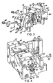
- the preferred scanner module consists of two separate sections: a chassis element 10 and a scan element 12. In Figure 3, these two sections are shown in exploded form, prior to their securement together during the assembly process.
- the chassis element 10 comprises a chassis 14 which carries the coil 172.
- the coil 172 is secured to a rear wall 16 of the chassis.
- At respective ends of the rear wall there are first and second forwardly-extending side supports 18, 20.
- the forward end of the side support 18 is provided with a vertical slot 22 ( Figure 5) into which is placed ( Figure 6) the collecting mirror 184 previously referred to.
- the forward part of the other side support 20 is provided with a larger vertical slot or cavity 24 ( Figure 5) into which the photodiode assembly 186 ( Figure 6) fits.
- the scan element 12 (which is during assembly secured to the chassis element 10) is best seen from a comparison of Figures 3, 4 and 6.
- the scan element comprises a beryllium-copper bracket generally shown at 26 having a vertical mounting portion 28 in a plane perpendicular to the axis of the coil 172.
- the upper part of the mounting portion is formed with two rearwardly-pointing prongs 30, 32 (not visible in Figure 6) which act a counterweights for the mirror 180.
- the spring 178 Secured to the mounting portion 28 is the spring 178, previously mentioned with reference to Figure 1, which carries the mirror 180.
- first and second hanging brackets 34, 36, best seen in Figures 3 and 4. Screwed to these hanging brackets are respective first and second sheets of Mylar film 38, only one of which is visible in Figures 3 to 5.
- At the top of the Mylar sheets are secured respective hangers 40, 42.
- the scanner module is assembled by bringing the scan element 12 up to the chassis element 10 and using screws 44, 46 to attach the hangers 40, 42 to respective bosses 48, 50 on the chassis side supports 18, 20.
- the relative positioning of the chassis element and the scan element, just prior to their securement together by the screws 44, 46 is shown most clearly in Figure 4.
- the entire weight of the scan element including the mirror 180, is supported by the hangers 40, 42 and the sheets of Mylar film 38.
- the entire scan element is accordingly free to rock back and forth about a horizontal axis perpendicular to the axis of the coil 172 as the Mylar film flexes.
- a laser beam emanating from the laser beam source and lens assembly 182, passes through the hole 181 in the collector 184, and impinges upon the mirror 180 from which it is reflected via a window 52 to a bar code symbol to be read (not shown).
- Energisation of the coil 172 causes oscillation of the mirror 180 in two directions: a first direction due to flexing of the spring 178 and a second direction due to flexing of the Mylar film 38.
- a variety of scanning patterns can be produced, for example a raster pattern or other types of two-dimensional pattern.
- the lower end of the hanging bracket 34 is located within a channel or cut out portion 54 formed in the side support 18 of the chassis. As the Mylar film 38 flexes, the hanging bracket 34 moves back and forth within the channel 54. The Mylar film 34 is prevented from over-flexing by the walls of the channel 54 which act as stops. A similar arrangement (not visible in the drawings) is provided on the other side.
- a second level of protection is provided by alignment pins 56, 58, best seen in Figure 3.
- Each pin comprises a threaded rear head portion 60, a reduced diameter smooth waist portion 62, and a smooth forward head portion 64.
- the waist portion 62 of the pin passes through a hole 68 in the hanging bracket 34, with the forward head portion 64 being received within a correspondingly-sized blind bore 70 within one side of the channel 54.
- the rear head portion 60 of the pin is screwed into and held in place by a threaded bore 66 which opens at its forward end into the channel 54 and at its rearward end into the rear surface of the rear wall 16.
- a threaded bore 66 which opens at its forward end into the channel 54 and at its rearward end into the rear surface of the rear wall 16.
- the diameter of the waist portion 62 of the pin is some 0.5 mm (0.02 inches) smaller than the diameter of the hole 68 in the hanging bracket. This provides sufficient tolerance for the Mylar to flex slightly during normal operation of the device. However, if the module is dropped the presence of the pin prevents over-stressing and perhaps breaking of the Mylar.
- the alignment pins have a further function of assisting accurate positioning of the scan element 12 with respect to the chassis during assembly.
- the scan element is brought up into approximately the correct position, and the alignment pins are then inserted as shown in Figure 4.
- the forward head portion 64 is a tight tolerance sliding fit both within the hole 68 in the hanging bracket and in the blind bore 70. This aligns the scan element to the pins and hence to the chassis.
- the scan element is then secured to the chassis, as previously described, using the screws 44, 46.
- the hangers 40, 42 provide a certain amount of adjustability or tolerance in positioning, thereby ensuring that the scan element can be attached to the chassis at the position defined by the alignment pins.
Landscapes
- Physics & Mathematics (AREA)
- Electromagnetism (AREA)
- Engineering & Computer Science (AREA)
- Health & Medical Sciences (AREA)
- General Health & Medical Sciences (AREA)
- Toxicology (AREA)
- Artificial Intelligence (AREA)
- Computer Vision & Pattern Recognition (AREA)
- General Physics & Mathematics (AREA)
- Theoretical Computer Science (AREA)
- Mechanical Optical Scanning Systems (AREA)
- Facsimile Scanning Arrangements (AREA)
Claims (28)
- Ein Abtastmodul zur Verwendung in einer Abtastvorrichtung zum Lesen von Indizien oder Anzeigemitteln mit Teilen unterschiedlicher Lichtreflektivität, wobei das Abtastmodul Folgendes aufweist:a) einen Rahmen (10);b) eine Abtastkomponente (12) angebracht am Rahmen für eine Schwingungs- oder Oszillationsbewegung, wobei die Abtastkomponente ein optisches Element (180) aufweist, um Licht in einem Abtastmuster über zu lesende Anzeigemittel zu tasten, wobei die Abtastkomponente eine Öffnung oder Apertur (68) darinnen aufweist; undc) ein Antistoßglied (56, 58) dadurch gekennzeichnet, dass das Antistoßglied durch die Öffnung in der Abtastkomponente verläuft und kleiner ist im Querschnitt als die Größe der Öffnung, wodurch ein Zwischenraum vorgesehen wird für die Abtastkomponente, um im Gebrauch zu schwingen, wobei aber eine übermäßige Bewegung der Abtastkomponente bezüglich des Rahmens im Falle, dass das Modul einem mechanischen Stoß ausgesetzt wird, verhindert wird.
- Abtastmodul nach Anspruch 1, wobei das Antistoßglied (56, 58) ein Stift ist, der einen ersten Kopfteil (60), einen zweiten Kopfteil (64) und einen Taillenteil (62) aufweist, der einen kleineren Querschnitt besitzt als die ersten und zweiten Kopfteile, wobei der Taillenteil innerhalb der Öffnung (68) während des Normalbetriebs des Abtastmoduls angeordnet ist.
- Abtastmodul nach Anspruch 2, wobei der erste Kopfteil (60) ein externes Schraubengewinde aufweist, welches derart angeordnet ist, dass es in eine Bohrung (66) im Rahmen eingeschraubt werden kann.
- Abtastmodul nach Anspruch 2, wobei der zweite Kopfteil (64) derart angeordnet ist, dass er innerhalb einer entsprechend bemessenen Bohrung (70) innerhalb des Rahmens aufgenommen wird.
- Abtastmodul nach Anspruch 2, wobei die Querschnittsgröße und -form des zweiten Kopfteils (64) der Größe und Form der Öffnung (68) entsprechen.
- Abtastmodul nach Anspruch 5, wobei der zweite Kopfteil (64) eine derartige Länge besitzt, dass der Stift im zweiten Kopfteil enthalten innerhalb der Öffnung angeordnet werden kann und sich von der Öffnung in eine entsprechend bemessene Bohrung innerhalb des Rahmens erstreckt, wodurch die Abtastkomponente bezüglich des Rahmens angeordnet ist.
- Abtastmodul nach Anspruch 3, wobei der erste Kopfteil (60) im Wesentlichen fluchtend mit dem Rahmen ist, wenn der Stift sich in der Position für den Normalbetrieb des Abtastmoduls befindet.
- Abtastmodul nach Anspruch 2, wobei der Stift (56, 58) sich über einen Ausschnittteil (54) des Rahmens erstreckt, wobei die Öffnung (68) sich in einem Teil der Abtastkomponente befindet, die sich in den erwähnten Ausschnittteil erstreckt.
- Abtastmodul nach Anspruch 8, wobei der erwähnte Teil der Abtastkomponente einen Hängebügel (34, 36) aufweist.
- Abtastmodul nach Anspruch 1, wobei die Öffnung (68) sich in einem Teil der Abtastkomponente befindet, die einen Hängebügel (34, 36) aufweist.
- Abtastmodul nach Anspruch 9 oder 10, wobei der Hängebügel (34, 36) von dem Rahmen durch ein biegsames bzw. Biegeglied (38) getragen ist.
- Abtastmodul nach Anspruch 11, wobei das biegsame Glied (38) eine . Polyestermaterialfolie bzw. einen -film aufweist.
- Abtastmodul nach Anspruch 1, wobei die Abtastkomponente (12) von dem Rahmen (10) durch ein biegsames Glied (38) getragen wird, wobei ferner die Abtastkomponente (12) Gegengewichtmittel (30, 32) aufweist, die die Masse des optischen Elementes (180) an einem biegsamen Glied (38) ausgleichen.
- Abtastmodul nach Anspruch 13, wobei ferner eine elektromagnetische Spule (172) am Rahmen (10) angebracht ist, und wobei die Gegengewichtmittel (30, 32) mindestens teilweise die Spule (172) überlappen oder darüber liegen.
- Abtastmodul nach Anspruch 1, wobei die Abtastkomponente von dem Rahmen (10) durch ein biegsames Glied (38) getragen ist, und wobei das optische Element (180) von der Abtastkomponente durch ein weiteres biegsames Glied (178) getragen wird, und wobei das biegsame Glied (38) und das weitere biegsame Glied (178) derart angeordnet sind, dass sie in gegenseitig senkrechten Richtungen sich biegen.
- Abtastmodul nach Anspruch 1, wobei erste und zweite Antistoßglieder (56, 58) vorgesehen sind, wobei das erste Antistoßglied (56) benachbart zu einer erste Seite des Rahmens vorgesehen ist, und wobei das zweite Antistoßglied (58) benachbart zu einer zweiten Seite des Rahmens vorgesehen ist.
- Abtastmodul nach Anspruch 1, wobei das Antistoßglied (56, 58) eine Längsachse besitzt, und wobei die Bewegung der Abtastkomponente an der Öffnung (68) während der Schwingung im Wesentlichen parallel zu der erwähnten Längsachse verläuft.
- Abtastmodul nach Anspruch 1, wobei das Antistoßglied (56, 58) einen Stift aufweist.
- Verfahren zum Zusammenbau eines Abtastmoduls zur Verwendung in einer Abtastvorrichtung zum Lesen von Anzeigemitteln mit Teilen von unterschiedlicher Reflektivität, wobei das Abtastmodul Folgendes aufweist: einen Rahmen (10);
eine Abtastkomponente (12) zum Anordnen am Rahmen zur Schwingungsbewegung, wobei die Abtastkomponente ein optisches Element (180) aufweist, um Licht in einem Abtastmuster über ein Anzeigemittel, welches gelesen werden soll, zu leiten, und wobei die Abtastkomponente ferner eine Öffnung (68) darinnen aufweist; und
wobei ein Antistoßstift (56, 58) einen ersten Kopfteil (60), einen zweiten Kopfteil (64) und einen Taillenteil (62) aufweist mit einem kleineren Querschnitt als die ersten und zweiten Kopfteile, wobei das Verfahren ferner Folgendes vorsieht:a) Positionieren der Abtastkomponente (12) benachbart zu dem Rahmen (10);b) teilweises Einsetzen des Stiftes (56, 58) in den Rahmen, so dass der zweite Kopfteil (64) durch die Öffnung (68) verläuft und sich von der Öffnung in eine entsprechend geformte Bohrung (70) im Rahmen erstreckt, wodurch die Abtastkomponente bezüglich des Rahmens ausgerichtet wird;c) Befestigen der Abtastkomponente (12) am Rahmen (10);d) Fortsetzen des Einsetzens des Stiftes (56, 58) in den Rahmen derart, dass der Taillenteil (62) des Stiftes innerhalb der Öffnung (68) angeordnet wird, wodurch ein Zwischenrahmen vorgesehen wird für die Abtastkomponente, um im Gebrauch zu schwingen, wobei aber verhindert wird, dass eine übermäßige Bewegung der Abtastkomponente bezüglich des Rahmens erfolgt, und zwar im Falle, dass das Modul einem mechanischen Stoß ausgesetzt wird. - Verfahren nach Anspruch 19, wobei der ersten Kopfteil (60) des Stiftes mit Gewinde versehen ist und aufgenommen wird innerhalb einer entsprechenden Gewindebohrung (66) innerhalb des Rahmens.
- Verfahren nach Anspruch 20, wobei die endgültige Stelle des Stiftes (56, 58) für den normalen Betrieb des Abtastmoduls durch eine Position definiert wird, in der der erste Kopfteil (60) des Stiftes mit dem Rahmen fluchtend ist.
- Abtastmodul nach Anspruch 1 bis 18 zur Verwendung in einer Abtastvorrichtung zum Lesen von Anzeigemitteln mit Teilen von unterschiedlicher Lichtreflektivität, wobei die Abtastkomponente (12) einen Hauptbügel (26) aufweist, und zwar angebracht an dem Rahmen durch flexible Tragmittel (38) zur Schwingbewegung, wobei der Hauptbügel (26) das optische Element trägt, und zwar zum Leiten von Licht in einem Abtastmuster über Anzeigemittel, die gelesen werden sollen, und
wobei ferner der Hauptbügel (26) die erwähnte Öffnung (68) darinnen aufweist;
wobei das Abtastmodul ferner Folgendes aufweist:d) eine elektromagnetische Spule (172) angebracht am Rahmen; unde) Magnetmittel (174) befestigt am Hauptbügel (26) benachbart zur Spule (172); undf) wobei der Hauptbügel (26) ferner einen Gegengewichtsteil (30, 32) aufweist zum Ausgleichen der Masse des optischen Elementes (180) an den flexiblen Tragmitteln (38), wobei der Gegengewichtsteil (30, 32) mindestens teilweise über der Spule (172) liegt. - Abtastmodul nach Anspruch 22, wobei der Rahmen (10) einen ersten Seitenteil (18), einen zweiten Seitenteil (20) und einen Rückenteil (16) aufweist, der die ersten und zweiten Seitenteile verbindet, und wobei die elektromagnetische Spule (172) zwischen den Seitenteilen (18, 20) angeordnet ist.
- Abtastmodul nach Anspruch 23, wobei ein optisches Kollektorelement (184) an dem ersten Seitenteil (18) angebracht ist.
- Abtastmodul nach Anspruch 23 mit einer Photodetektoreinheit (186) angebracht an dem zweiten Seitenteil (20).
- Abtastmodul nach Anspruch 23, wobei die ersten und zweiten Seitenteile (18, 20) jeweils entsprechende Ausschnittteile (54) aufweisen, innerhalb derer die entsprechenden Hängebügel (34, 36) des Hauptbügels (26) aufgenommen werden.
- Abtastmodul nach Anspruch 26, wobei die Hängebügel (34, 36) am Rahmen durch entsprechende Biegeglieder (38) angebracht sind.
- Abtastmodul nach Anspruch 27, wobei die biegsamen Glieder (38) Polyestermaterialfolien oder -filme sind.
Priority Applications (1)
| Application Number | Priority Date | Filing Date | Title |
|---|---|---|---|
| EP03003186A EP1310903B1 (de) | 1993-11-17 | 1994-11-11 | Kompakter Strichcodeabtaster mit Stossschutz |
Applications Claiming Priority (4)
| Application Number | Priority Date | Filing Date | Title |
|---|---|---|---|
| US326328 | 1989-03-21 | ||
| US08/153,053 US5504316A (en) | 1990-05-08 | 1993-11-17 | Laser scanning system and scanning method for reading 1-D and 2-D barcode symbols |
| US153053 | 1993-11-17 | ||
| US08/326,328 US5581067A (en) | 1990-05-08 | 1994-10-20 | Compact bar code scanning module with shock protection |
Related Child Applications (1)
| Application Number | Title | Priority Date | Filing Date |
|---|---|---|---|
| EP03003186A Division EP1310903B1 (de) | 1993-11-17 | 1994-11-11 | Kompakter Strichcodeabtaster mit Stossschutz |
Publications (3)
| Publication Number | Publication Date |
|---|---|
| EP0653723A2 EP0653723A2 (de) | 1995-05-17 |
| EP0653723A3 EP0653723A3 (de) | 2000-02-09 |
| EP0653723B1 true EP0653723B1 (de) | 2003-10-01 |
Family
ID=26850112
Family Applications (2)
| Application Number | Title | Priority Date | Filing Date |
|---|---|---|---|
| EP94117879A Expired - Lifetime EP0653723B1 (de) | 1993-11-17 | 1994-11-11 | Abtastelement mit Stosschutz |
| EP03003186A Expired - Lifetime EP1310903B1 (de) | 1993-11-17 | 1994-11-11 | Kompakter Strichcodeabtaster mit Stossschutz |
Family Applications After (1)
| Application Number | Title | Priority Date | Filing Date |
|---|---|---|---|
| EP03003186A Expired - Lifetime EP1310903B1 (de) | 1993-11-17 | 1994-11-11 | Kompakter Strichcodeabtaster mit Stossschutz |
Country Status (5)
| Country | Link |
|---|---|
| US (2) | US5581067A (de) |
| EP (2) | EP0653723B1 (de) |
| JP (1) | JPH07254041A (de) |
| CA (1) | CA2136046A1 (de) |
| DE (2) | DE69433196T2 (de) |
Families Citing this family (42)
| Publication number | Priority date | Publication date | Assignee | Title |
|---|---|---|---|---|
| US6575370B1 (en) * | 1990-05-08 | 2003-06-10 | Symbol Technologies, Inc. | Electro-optical scanning assembly with one-piece, oscillatable, focusing/scan element |
| US6227450B1 (en) | 1990-09-11 | 2001-05-08 | Metrologic Instruments, Inc. | Electronically-controlled mechanically-damped off-resonant light beam scanning mechanism and code symbol readers employing the same |
| US6742709B2 (en) | 1990-09-11 | 2004-06-01 | Metrologic Instruments, Inc. | Bar code symbol reading system employing electronically-controlled raster-type laser scanner for reading bar code symbols during hands-on and hands-free modes of operation |
| US6874689B2 (en) * | 1990-09-11 | 2005-04-05 | Metrologic Instruments, Inc. | Laser beam scanning device employing a scanning element having a flexible photo-etched gap region disposed between an anchored base portion and a light beam deflecting portion having a natural frequency of oscillation tuned by the physical dimensions of said flexible photo-etched gap region and forcibly oscillated about a fixed pivot point at an electronically-controlled frequency of oscillation substantially different from said natural resonant frequency of oscillation |
| US6114712A (en) * | 1996-10-09 | 2000-09-05 | Symbol Technologies, Inc. | One piece optical assembly for low cost optical scanner |
| NL9400924A (nl) * | 1994-06-08 | 1996-01-02 | Scantech Bv | Inrichting voor het aftasten van gecodeerde informatie. |
| US6085978A (en) * | 1994-08-17 | 2000-07-11 | Metrologic Instruments, Inc. | Holographic laser scanners of modular construction and method and apparatus for designing and manufacturing the same |
| JP3379837B2 (ja) * | 1994-10-27 | 2003-02-24 | 富士通株式会社 | 光学読取装置 |
| JPH0991368A (ja) * | 1995-07-20 | 1997-04-04 | Fujitsu Ltd | 光学読取装置 |
| EP0745950A1 (de) * | 1995-05-30 | 1996-12-04 | Opticon Sensors Europe B.V. | Optisches Abtastgerät zur Erzeugung einer schraubenförmigen Musterabtastung auf einer (zylindrischen) Aussenoberfläche |
| EP0753823A1 (de) * | 1995-07-05 | 1997-01-15 | Opticon Sensors Europe B.V. | Optischer Abtaster zur Erzeugung von Abtastzeilen auf allen Seiten eines Objektes |
| US6811086B1 (en) | 1995-07-20 | 2004-11-02 | Fujitsu Limited | Stand for pivotably mounting an optical reading device |
| US6360949B1 (en) | 1995-10-10 | 2002-03-26 | Symbol Technologies, Inc. | Retro-reflective scan module for electro-optical readers |
| US20020014533A1 (en) | 1995-12-18 | 2002-02-07 | Xiaxun Zhu | Automated object dimensioning system employing contour tracing, vertice detection, and forner point detection and reduction methods on 2-d range data maps |
| US5909302A (en) * | 1996-08-02 | 1999-06-01 | Guissin; Rami | Staring scanner |
| US7124950B2 (en) * | 1997-09-16 | 2006-10-24 | Metrologic Instruments, Inc. | Bar code symbol reading system employing electronically-controlled raster-type laser scanner for reading bar code symbols during on hands-on and hands-free modes of operation |
| US7028899B2 (en) | 1999-06-07 | 2006-04-18 | Metrologic Instruments, Inc. | Method of speckle-noise pattern reduction and apparatus therefore based on reducing the temporal-coherence of the planar laser illumination beam before it illuminates the target object by applying temporal phase modulation techniques during the transmission of the plib towards the target |
| US6592040B2 (en) * | 1998-03-20 | 2003-07-15 | Symbol Technologies, Inc. | Hand-held bar code reader with single printed circuit board |
| US6612496B1 (en) | 2000-03-16 | 2003-09-02 | Symbol Technologies, Inc. | Scan module |
| US6941026B1 (en) | 2000-06-13 | 2005-09-06 | Cognex Corporation | Method and apparatus using intensity gradients for visual identification of 2D matrix symbols |
| WO2002013227A1 (en) * | 2000-07-27 | 2002-02-14 | Ebara Corporation | Sheet beam test apparatus |
| US6523751B2 (en) * | 2000-12-15 | 2003-02-25 | Yu-Chun Chang | Scanning apparatus |
| JP4364482B2 (ja) | 2002-04-23 | 2009-11-18 | 株式会社キーエンス | 光学シンボル読取装置用光学ユニット |
| US7086596B2 (en) | 2003-01-09 | 2006-08-08 | Hand Held Products, Inc. | Decoder board for an optical reader utilizing a plurality of imaging formats |
| US8002183B2 (en) | 2005-10-20 | 2011-08-23 | Metrologic Instruments, Inc. | Scanner flipper integrity indicator |
| US7614561B2 (en) * | 2005-12-16 | 2009-11-10 | Metrologic Instruments, Inc. | Scanner flipper oscillation frequency detection and adjustment thereof |
| US7832641B2 (en) | 2007-05-24 | 2010-11-16 | Metrologic Instruments, Inc. | Scanner switched to active state by sensed movement in quiescent scanning mechanism |
| US7726575B2 (en) * | 2007-08-10 | 2010-06-01 | Hand Held Products, Inc. | Indicia reading terminal having spatial measurement functionality |
| US8643717B2 (en) * | 2009-03-04 | 2014-02-04 | Hand Held Products, Inc. | System and method for measuring irregular objects with a single camera |
| US8294969B2 (en) * | 2009-09-23 | 2012-10-23 | Metrologic Instruments, Inc. | Scan element for use in scanning light and method of making the same |
| US8390909B2 (en) | 2009-09-23 | 2013-03-05 | Metrologic Instruments, Inc. | Molded elastomeric flexural elements for use in a laser scanning assemblies and scanners, and methods of manufacturing, tuning and adjusting the same |
| US8059324B2 (en) | 2009-09-23 | 2011-11-15 | Metrologic Instruments, Inc. | Scan element for use in scanning light and method of making the same |
| US8748741B2 (en) | 2010-10-25 | 2014-06-10 | Tyco Electronics Corporation | Corrosion resistant multiple tap connectors |
| US8589801B2 (en) * | 2010-11-29 | 2013-11-19 | International Business Machines Corporation | Display screen user identification card for access to secured databases |
| US8915439B2 (en) | 2012-02-06 | 2014-12-23 | Metrologic Instruments, Inc. | Laser scanning modules embodying silicone scan element with torsional hinges |
| WO2013137882A2 (en) * | 2012-03-15 | 2013-09-19 | Optoelectronics Co., Ltd. | Scan unit for a scanning module |
| US8746563B2 (en) | 2012-06-10 | 2014-06-10 | Metrologic Instruments, Inc. | Laser scanning module with rotatably adjustable laser scanning assembly |
| JP6525895B2 (ja) * | 2013-03-15 | 2019-06-05 | コーニンクレッカ フィリップス エヌ ヴェKoninklijke Philips N.V. | バーコードリーダーを備える除細動器及びデータを記録する方法 |
| US9310609B2 (en) | 2014-07-25 | 2016-04-12 | Hand Held Products, Inc. | Axially reinforced flexible scan element |
| WO2018071684A1 (en) * | 2016-10-12 | 2018-04-19 | Cubic Corporation | Optical sensor for range finding and wind sensing measurements |
| JP7152147B2 (ja) * | 2017-12-04 | 2022-10-12 | パイオニア株式会社 | 測距装置 |
| US11288469B2 (en) | 2019-12-13 | 2022-03-29 | Zebra Technologies Corporation | Industrial digital barcode reader |
Citations (2)
| Publication number | Priority date | Publication date | Assignee | Title |
|---|---|---|---|---|
| US5235167A (en) * | 1988-10-21 | 1993-08-10 | Symbol Technologies, Inc. | Laser scanning system and scanning method for reading bar codes |
| EP0574024A2 (de) * | 1992-06-12 | 1993-12-15 | Symbol Technologies, Inc. | Anpassbarer Strichkodeleser |
Family Cites Families (19)
| Publication number | Priority date | Publication date | Assignee | Title |
|---|---|---|---|---|
| US4845350B1 (en) * | 1982-01-25 | 1991-04-30 | Narrow-bodied,single-and twin-windowed portable laser scanning head for reading bar code symbols | |
| US5122644A (en) * | 1988-11-17 | 1992-06-16 | Alps Electric Co., Ltd. | Optical code reading device with autofocussing |
| US4962980A (en) * | 1989-01-23 | 1990-10-16 | Metrologic Instruments, Inc. | Laser scanner engine with folded beam path |
| US4971410A (en) * | 1989-07-27 | 1990-11-20 | Ncr Corporation | Scanning and collection system for a compact laser |
| JP2808735B2 (ja) * | 1989-10-25 | 1998-10-08 | 富士通株式会社 | 分離型読取装置 |
| US5168149A (en) * | 1989-10-30 | 1992-12-01 | Symbol Technologies, Inc. | Scan pattern generators for bar code symbol readers |
| US5262627A (en) * | 1989-10-30 | 1993-11-16 | Symbol Technologies, Inc. | Scanning arrangement and method |
| US5206492A (en) * | 1989-10-30 | 1993-04-27 | Symbol Technologies, Inc. | Bar code symbol scanner with reduced power usage to effect reading |
| JP2711158B2 (ja) * | 1989-11-13 | 1998-02-10 | 富士写真フイルム株式会社 | 共振周波数安定化方法および共振型光偏向器 |
| US5115120A (en) * | 1990-06-26 | 1992-05-19 | Photographic Sciences Corporation | Scan modules for bar code readers and in which scan elements are flexurally supported |
| US5268564A (en) * | 1990-08-03 | 1993-12-07 | Symbol Technologies, Inc. | Bar code scanner actuated by detection of scanner motion |
| US5149949A (en) * | 1990-12-10 | 1992-09-22 | Ncr Corporation | Optical scanner with counterrotating reflector elements |
| US5212371A (en) * | 1991-03-01 | 1993-05-18 | Psc, Inc. | Hand held bar code scanner with improved aiming means |
| US5198651A (en) * | 1991-05-03 | 1993-03-30 | Symbol Technologies, Inc. | Laser diode device incorporating structure with integral scanning motor |
| CA2056272C (en) * | 1991-06-14 | 2001-10-16 | Patrick Salatto, Jr. | Combined range laser scanner |
| US5179271A (en) * | 1991-09-19 | 1993-01-12 | Ncr Corporation | Compact optical scan pattern generator for bar code reading systems |
| US5298729A (en) * | 1992-02-14 | 1994-03-29 | Ncr Corporation | Multiple depth of field optical scanner |
| IT1264733B1 (it) * | 1993-11-04 | 1996-10-04 | Datalogic Spa | Dispositivo di lettura o scanner a laser per la lettura di caratteri aventi un diverso grado di riflettenza, in particolare di codici a |
| US5475208A (en) * | 1994-01-27 | 1995-12-12 | Symbol Technologies, Inc. | Barcode scanner having a dead zone reducing system and a multifocal length collector |
-
1994
- 1994-10-20 US US08/326,328 patent/US5581067A/en not_active Expired - Lifetime
- 1994-11-11 DE DE69433196T patent/DE69433196T2/de not_active Expired - Lifetime
- 1994-11-11 EP EP94117879A patent/EP0653723B1/de not_active Expired - Lifetime
- 1994-11-11 DE DE69435305T patent/DE69435305D1/de not_active Expired - Lifetime
- 1994-11-11 EP EP03003186A patent/EP1310903B1/de not_active Expired - Lifetime
- 1994-11-17 JP JP6283700A patent/JPH07254041A/ja active Pending
- 1994-11-17 CA CA002136046A patent/CA2136046A1/en not_active Abandoned
-
1996
- 1996-06-05 US US08/658,383 patent/US5763863A/en not_active Expired - Lifetime
Patent Citations (2)
| Publication number | Priority date | Publication date | Assignee | Title |
|---|---|---|---|---|
| US5235167A (en) * | 1988-10-21 | 1993-08-10 | Symbol Technologies, Inc. | Laser scanning system and scanning method for reading bar codes |
| EP0574024A2 (de) * | 1992-06-12 | 1993-12-15 | Symbol Technologies, Inc. | Anpassbarer Strichkodeleser |
Also Published As
| Publication number | Publication date |
|---|---|
| US5581067A (en) | 1996-12-03 |
| CA2136046A1 (en) | 1995-05-18 |
| DE69435305D1 (de) | 2010-09-02 |
| US5763863A (en) | 1998-06-09 |
| DE69433196T2 (de) | 2004-07-29 |
| EP0653723A3 (de) | 2000-02-09 |
| EP1310903A1 (de) | 2003-05-14 |
| EP0653723A2 (de) | 1995-05-17 |
| JPH07254041A (ja) | 1995-10-03 |
| DE69433196D1 (de) | 2003-11-06 |
| EP1310903B1 (de) | 2010-07-21 |
Similar Documents
| Publication | Publication Date | Title |
|---|---|---|
| EP0653723B1 (de) | Abtastelement mit Stosschutz | |
| US5486944A (en) | Scanner module for symbol scanning system | |
| EP0368254B1 (de) | Abtastmodule für Streifencode-Leser und gleichartiges | |
| EP0818750B1 (de) | Dünner Abtastermodul | |
| US6527183B2 (en) | One piece optical assembly for low cost optical scanner | |
| US6142379A (en) | Compact bar code scanner with scan mirror jointly movable with drive component | |
| CA2084212C (en) | Scanning arrangement and method | |
| US6491222B1 (en) | Optical path design for scanning assembly in compact bar code readers | |
| US5665954A (en) | Electro-optical scanner module having dual electro-magnetic coils | |
| US20050092841A1 (en) | Monitoring bi-directional motor drive failure in electro-optical reader | |
| AU780839B2 (en) | Compact dual optical and scan modules in bar code readers | |
| US5543609A (en) | Arrangement for and method of providing shock protection and vibration isolation for a scan module | |
| US6722566B1 (en) | Electro-optical scan module using selectable mirrors | |
| US20050242187A1 (en) | Synchronous and resonant drives for producing multiple scan line pattern for electro-optically reading indicia | |
| EP1209613B1 (de) | Kompakte Strichkode- Abtastanordnung | |
| EP1854045B1 (de) | Scanmodul | |
| US6112993A (en) | Flexible dither mount with rotation | |
| CA2111934C (en) | Scanner module for symbol scanning system | |
| US7017815B2 (en) | Compact externally-driven scanner | |
| WO2006124210A1 (en) | Method and apparatus for shock protection | |
| US20060255142A1 (en) | Methods and apparatus for shock protection |
Legal Events
| Date | Code | Title | Description |
|---|---|---|---|
| PUAI | Public reference made under article 153(3) epc to a published international application that has entered the european phase |
Free format text: ORIGINAL CODE: 0009012 |
|
| AK | Designated contracting states |
Kind code of ref document: A2 Designated state(s): DE FR GB IT |
|
| PUAL | Search report despatched |
Free format text: ORIGINAL CODE: 0009013 |
|
| AK | Designated contracting states |
Kind code of ref document: A3 Designated state(s): DE FR GB IT |
|
| 17P | Request for examination filed |
Effective date: 20000802 |
|
| 17Q | First examination report despatched |
Effective date: 20010116 |
|
| GRAG | Despatch of communication of intention to grant |
Free format text: ORIGINAL CODE: EPIDOS AGRA |
|
| RTI1 | Title (correction) |
Free format text: SCAN MODULE WITH SHOCK PROTECTION |
|
| GRAG | Despatch of communication of intention to grant |
Free format text: ORIGINAL CODE: EPIDOS AGRA |
|
| GRAH | Despatch of communication of intention to grant a patent |
Free format text: ORIGINAL CODE: EPIDOS IGRA |
|
| GRAS | Grant fee paid |
Free format text: ORIGINAL CODE: EPIDOSNIGR3 |
|
| GRAA | (expected) grant |
Free format text: ORIGINAL CODE: 0009210 |
|
| AK | Designated contracting states |
Kind code of ref document: B1 Designated state(s): DE FR GB IT |
|
| REG | Reference to a national code |
Ref country code: GB Ref legal event code: FG4D |
|
| REF | Corresponds to: |
Ref document number: 69433196 Country of ref document: DE Date of ref document: 20031106 Kind code of ref document: P |
|
| RAP2 | Party data changed (patent owner data changed or rights of a patent transferred) |
Owner name: SYMBOL TECHNOLOGIES, INC. |
|
| ET | Fr: translation filed | ||
| PLBE | No opposition filed within time limit |
Free format text: ORIGINAL CODE: 0009261 |
|
| STAA | Information on the status of an ep patent application or granted ep patent |
Free format text: STATUS: NO OPPOSITION FILED WITHIN TIME LIMIT |
|
| 26N | No opposition filed |
Effective date: 20040702 |
|
| REG | Reference to a national code |
Ref country code: DE Ref legal event code: R082 Ref document number: 69433196 Country of ref document: DE Representative=s name: SCHUMACHER & WILLSAU PATENTANWALTSGESELLSCHAFT, DE |
|
| PGFP | Annual fee paid to national office [announced via postgrant information from national office to epo] |
Ref country code: DE Payment date: 20121130 Year of fee payment: 19 Ref country code: FR Payment date: 20121113 Year of fee payment: 19 |
|
| PGFP | Annual fee paid to national office [announced via postgrant information from national office to epo] |
Ref country code: IT Payment date: 20121119 Year of fee payment: 19 Ref country code: GB Payment date: 20121025 Year of fee payment: 19 |
|
| GBPC | Gb: european patent ceased through non-payment of renewal fee |
Effective date: 20131111 |
|
| REG | Reference to a national code |
Ref country code: FR Ref legal event code: ST Effective date: 20140731 |
|
| REG | Reference to a national code |
Ref country code: DE Ref legal event code: R119 Ref document number: 69433196 Country of ref document: DE Effective date: 20140603 |
|
| PG25 | Lapsed in a contracting state [announced via postgrant information from national office to epo] |
Ref country code: IT Free format text: LAPSE BECAUSE OF NON-PAYMENT OF DUE FEES Effective date: 20131111 Ref country code: DE Free format text: LAPSE BECAUSE OF NON-PAYMENT OF DUE FEES Effective date: 20140603 |
|
| PG25 | Lapsed in a contracting state [announced via postgrant information from national office to epo] |
Ref country code: GB Free format text: LAPSE BECAUSE OF NON-PAYMENT OF DUE FEES Effective date: 20131111 Ref country code: FR Free format text: LAPSE BECAUSE OF NON-PAYMENT OF DUE FEES Effective date: 20131202 |