EP0653725A2 - Koordinateneingabegerät - Google Patents
Koordinateneingabegerät Download PDFInfo
- Publication number
- EP0653725A2 EP0653725A2 EP94117867A EP94117867A EP0653725A2 EP 0653725 A2 EP0653725 A2 EP 0653725A2 EP 94117867 A EP94117867 A EP 94117867A EP 94117867 A EP94117867 A EP 94117867A EP 0653725 A2 EP0653725 A2 EP 0653725A2
- Authority
- EP
- European Patent Office
- Prior art keywords
- input device
- coordinate input
- pressure sensor
- grip
- sensor
- Prior art date
- Legal status (The legal status is an assumption and is not a legal conclusion. Google has not performed a legal analysis and makes no representation as to the accuracy of the status listed.)
- Granted
Links
Images


Classifications
-
- G—PHYSICS
- G06—COMPUTING OR CALCULATING; COUNTING
- G06F—ELECTRIC DIGITAL DATA PROCESSING
- G06F3/00—Input arrangements for transferring data to be processed into a form capable of being handled by the computer; Output arrangements for transferring data from processing unit to output unit, e.g. interface arrangements
- G06F3/01—Input arrangements or combined input and output arrangements for interaction between user and computer
- G06F3/03—Arrangements for converting the position or the displacement of a member into a coded form
- G06F3/033—Pointing devices displaced or positioned by the user, e.g. mice, trackballs, pens or joysticks; Accessories therefor
- G06F3/038—Control and interface arrangements therefor, e.g. drivers or device-embedded control circuitry
-
- G—PHYSICS
- G06—COMPUTING OR CALCULATING; COUNTING
- G06F—ELECTRIC DIGITAL DATA PROCESSING
- G06F3/00—Input arrangements for transferring data to be processed into a form capable of being handled by the computer; Output arrangements for transferring data from processing unit to output unit, e.g. interface arrangements
- G06F3/01—Input arrangements or combined input and output arrangements for interaction between user and computer
- G06F3/03—Arrangements for converting the position or the displacement of a member into a coded form
- G06F3/033—Pointing devices displaced or positioned by the user, e.g. mice, trackballs, pens or joysticks; Accessories therefor
- G06F3/0354—Pointing devices displaced or positioned by the user, e.g. mice, trackballs, pens or joysticks; Accessories therefor with detection of two-dimensional [2D] relative movements between the device, or an operating part thereof, and a plane or surface, e.g. 2D mice, trackballs, pens or pucks
- G06F3/03543—Mice or pucks
Definitions
- the present invention relates to a coordinate input device, and more particularly to a mouse whose movements on a flat surface are reflected by cursor movements on a visual display unit of a computer system.
- the coordinate input device such as the mouse is widely used for the computer system in the business use for the office work, engineering or the like, as well as in the personal use for playing the video game. drawing the picture or making the document containing tables.
- This device is useful in inputting two-dimensional coordinates, which designate a location to input a character on the screen or a location to start drawing a picture on the screen.
- the cursor displayed on the screen of the visual display unit is controlled in location or coordinates by that device.
- FIG. 2A is a sectional view showing a mechanical structure of the coordinate input device conventionally known.
- This is a so-called mechanical mouse in which a rubber-coated ball 22 is rolling on a flat surface 31 so that the amounts of movements in X and Y directions are detected. Those movements are reflected by the two-dimensional movements of the cursor on the screen.
- This type of mouse is frequently used in the personal computer system.
- a substrate 21 is fixedly located inside of a main body 20. Due to the provision of the main body 20, the substrate 21 and a ball-positioning member 24, the ball 22 is located at a certain position such that the ball 22 can rotate in any directions. The rotation of the ball 22 is converted into the location of the device on the flat surface 31.
- FIG. 2B shows a construction of a rotation detector 26.
- a slit disk 34 is attached to an axis 32 such that the slit disk 34 can rotate about the axis 32.
- a plurality of slits are formed in the peripheral portion of the slit disk 34 at equal intervals.
- a light-emitting element 36 is placed against a light-receiving element 38 with respect to the slit disk 34. The detection for the rotation of the ball 22 is activated when the operator moves the device in a certain direction on the flat surface 31 so that the ball 22 is correspondingly rotated.
- the slit disk 34 normally comes in contact with the ball 22; hence, the slit disk 34 should be rotated about the axis 32 by a certain amount of rotation in response to the rotation of the ball 22.
- the light emitted from the light-emitting element 36 passes through the slit to reach the light-receiving element 38. Since the slit disk 34 rotates responsive to the rotation of the ball 22, the light should intermittently reach the light-receiving element 38; in other words, the light-receiving element 38 receives a certain number of pulses of light in accordance with the rotation of the slit disk 34.
- the number of the pluses of light, received by the light-receiving element 38, is proportional to the amount of rotation of the ball 22 in a certain direction.
- the rotation detector 26, as shown in FIG. 2B, is provided for each of the X and Y directions; hence, it is possible to detect the amount of rotation of the ball 22 with respect to each of the X and Y directions.
- the pulses of light, received by the light-receiving element 38, are converted into electric signals by a movement detecting means 28; and then, those electric signals are outputted from the device.
- FIG. 3 is a sectional view showing a mechanical structure of another coordinate input device conventionally known.
- This is a so-called opto-mechanical mouse having an optical detection means 46 by which the movements thereof are detected by reading a pattern written on a pad 40 so as to compute the amounts of movements in X and Y directions by a data conversion means 48.
- buttons 29 and 49 are respectively connected with click detectors 30 and 50 which are fixedly located inside of the main body 20.
- the click detectors 30 and 50 detect ON/OFF states of the buttons 29 and 49 respectively, so that conversion means (not shown) converts the ON/OFF states detected into electric signals, which are outputted from the device.
- the application program executed by the computer, determines how the buttons function. For example, a task to select a specific function is assigned to one button, while a task to correct a specific item is assigned to another button.
- the coordinate input devices conventionally known are useful in providing sufficient information regarding a two-dimensional coordinates system. Recently, however, video-game softwares or multi-media systems require more complicated movements for the cursor or graphic image on the screen. In some cases, three-dimensional movements are required. In that case, the conventional coordinate input device cannot sufficiently satisfy those needs.
- the conventional device When inputting a size or an intensity as a parameter regarding a certain object to be controlled on the screen, the conventional device inputs such parameter by detecting a timing to push the button or a duration in which the button is continuously pushed.
- Such indirect detection should be made by the conventional device because of the limited mechanism of the device.
- a change of the parameter on the screen which is caused by the conventional device does not precisely match with the operator's intention.
- the operator should be skilled in manipulating the device. Therefore, the conventional device is not designed for the normal people who are not necessarily skilled in manipulating the device.
- the conventional device cannot establish a good relationship between the screen image and the manipulation thereof.
- the present invention provides improvements for the coordinate input devices such as the mechanical mouse, opto-mechanical mouse or the like which are used to control cursor movements in the visual display unit of the computer system.
- the coordinate input device according to the present invention comprises a position sensor and a pressure sensor.
- the position sensor detects a two-dimensional position of the device, which is moved on a flat surface or the like by a person, so as to produce two-dimensional coordinates.
- the pressure sensor detects pressing force applied to the device by the person. Hence, the two-dimensional coordinates and the pressing force detected are used as parameters which control a cursor or a graphic image displayed on the screen of the visual display unit.
- the pressure sensor comprises an air-pressure sensor which detects a change of an air pressure caused by the pressing force applied to the device.
- the pressure sensor can be replaced by a grip sensor which detects grip force applied to the device by the person.
- FIG. 1 is a sectional view illustrating a mechanical structure of a coordinate input device according to a first embodiment of the present invention.
- a numeral 1 denotes a position sensor which detects the movements thereof in the X and Y directions; and a numeral 2 denotes an air layer which is sealed by a pump 9.
- the pump 9 is made by specific material by which a part of the pump 9 or an overall portion of the pump 9 is made flexible.
- the air layer 2 is placed outside of an upper case 4 which is provided to protect an internal mechanism of the device. When an operator holds or grasps the upper case 4, a certain air pressure occurs in the air layer 2.
- a numeral 3 denotes an air-pressures sensor, a part of which is connected with a part of the air layer 2 sealed.
- the air-pressure sensor 3 can detect a change of the air pressure which occurs in the air layer 2.
- a numeral 5 denotes a lower case; a numeral 6 denotes a push button which is pushed by the operator; and a numeral 7 denotes a cable by which a variety of information created by the device is transmitted to an external device or the like.
- the position sensor 1 it is possible to use a speed sensor which acts responsive to the inertia. In that case, the device can be moved in the space without being supported by a flat pad or the like.
- the position sensor 1 is embodied by a sensor whose output is proportional to the amount of movement or the speed in each of the X and Y directions in the two-dimensional coordinates system. Therefore, it is possible to use a mechanical-type sensor or an optical-type sensor as similar to one of the coordinate input devices shown in FIGS. 2A, 2B and 3.
- the first embodiment shown in FIG. 1 provides the air-pressure sensor 3, detecting the air pressure which responds to the operator's action to grasp the upper case 4. Therefore, the first embodiment is advantageous in that a variety of expressions can be realized on the screen. For example, when controlling a graphic image which represents an animated character in the video game to be played on the screen, the first embodiment can offer the three-dimensional movements as well as the two-dimensional movements on the screen.
- FIG. 4 is sectional view illustrating a mechanical structure of a coordinate input device according to a second embodiment of the present invention.
- the parts corresponding to those shown in FIG. 1 are designated by the same numerals; hence, the description thereof will be omitted.
- the second embodiment is characterized by that the sealed air layer 2 is located inside of the lower case 5.
- the air layer 2 is compressed so that a change of the air pressure occurs, which is detected by the air-pressure sensor 3.
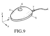
- FIG. 9 is a perspective view illustrating the appearance of the coordinate input device shown in FIG. 4.
- the second embodiment by merely operating and moving the coordinate input device on the flat pad, it is possible to obtain information representative of the parameter regarding a Z direction, which is a vertical direction against the flat pad, as well as the information regarding the two-dimensional parameters (i.e., the X- and Y-direction movements) of the device moved on the flat pad.
- the second embodiment can provide three-dimensional parameters.
- FIG. 5 is a block diagram showing an electric configuration of the coordinate input device.
- the position sensor 1 consists of two sensors, i.e., an X-direction sensor 1A and a Y-direction sensor 1B.
- a numeral 9 denotes an AD converter which receives analog outputs of the X-direction sensor 1A, the Y-direction sensor 1B and the air-pressure sensor 3. Therefore, those analog outputs are converted into digital data by the AD converter 9, so that the digital data are transmitted through the cable 7.
- FIG. 6 is a circuit diagram showing an electric configuration of the air-pressure sensor 3.
- the air-pressure sensor 3 is configured by a pressure-sensitive element 3A, an operational amplifier 3B and resistors R1-R4.
- the pressure-sensitive element 3A produces an analog voltage which is proportional to a pressure difference between the internal pressure of the air layer 2 and the atmospheric pressure, wherein the internal pressure of the air layer 2 is changed when the operator grasps the upper case 4 shown in FIG. 3.
- the operational amplifier 3B and the resistors R1-R4 are assembled together to form a differential amplifier.
- the analog voltage which is produced responsive to the pressure difference described above, is amplified by the amplifier so as to produce a dc voltage which is outputted from the air-pressure sensor 3.
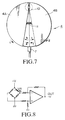
- FIG. 7 is a plan view illustrating a coordinate input device according to a third embodiment of the present invention.
- the third embodiment is characterized by providing a grip sensor, wherein a grip force applied to the upper case 4 is not reflected by the change of the air pressure but by the mechanical rotation. Hence, a rotation angle, which is changed responsive to the rotation force corresponding to the grip force applied to the upper case 4, is converted into voltage change.
- the upper case 4 is divided into two sections 4A and 4B which are rotatably moved in opposite directions (see arrows 'c' , 'd', 'e' and 'f') about a rotation center 10 in response to the force to grasp those sections 4A and 4B.
- the rotation center 10 includes a variable resistor VR whose resistance is varied responsive to pressure applied thereto. Hence, when the operator grasps the upper case 4, certain pressure is applied to the variable resistor VR so that its resistance is changed. The change of the resistance is converted into the voltage change. Further, a numeral 11 denotes a spring which is provided between the two sections 4A and 4B.
- FIG. 8 is a circuit diagram showing an electric configuration of the grip sensor which contains a resistor bridge circuit including the variable resistor VR.
Landscapes
- Engineering & Computer Science (AREA)
- General Engineering & Computer Science (AREA)
- Theoretical Computer Science (AREA)
- Human Computer Interaction (AREA)
- Physics & Mathematics (AREA)
- General Physics & Mathematics (AREA)
- Position Input By Displaying (AREA)
Applications Claiming Priority (3)
| Application Number | Priority Date | Filing Date | Title |
|---|---|---|---|
| JP309740/93 | 1993-11-15 | ||
| JP30974093A JP3381344B2 (ja) | 1993-11-15 | 1993-11-15 | 座標入力装置 |
| JP30974093 | 1993-11-15 |
Publications (3)
| Publication Number | Publication Date |
|---|---|
| EP0653725A2 true EP0653725A2 (de) | 1995-05-17 |
| EP0653725A3 EP0653725A3 (de) | 1996-02-07 |
| EP0653725B1 EP0653725B1 (de) | 2001-10-10 |
Family
ID=17996733
Family Applications (1)
| Application Number | Title | Priority Date | Filing Date |
|---|---|---|---|
| EP94117867A Expired - Lifetime EP0653725B1 (de) | 1993-11-15 | 1994-11-11 | Koordinateneingabegerät |
Country Status (5)
| Country | Link |
|---|---|
| US (2) | US5717610A (de) |
| EP (1) | EP0653725B1 (de) |
| JP (1) | JP3381344B2 (de) |
| DE (1) | DE69428566T2 (de) |
| TW (1) | TW347127U (de) |
Cited By (7)
| Publication number | Priority date | Publication date | Assignee | Title |
|---|---|---|---|---|
| EP0750249A1 (de) * | 1995-06-23 | 1996-12-27 | Director-General Of The Agency Of Industrial Science And Technology | Rechnergestütztes Entwurfssystem |
| WO2003028003A3 (de) * | 2001-09-21 | 2004-03-25 | 3Dconnexion Gmbh | Kombinierter positions-/kraftmomentensensor |
| US7215323B2 (en) | 2001-09-21 | 2007-05-08 | 3Dconnexion Gmbh | Three-dimensional integrated tough screen input apparatus |
| WO2006132817A3 (en) * | 2005-06-03 | 2007-08-09 | Apple Computer | Mouse with improved input mechanisms |
| US9785258B2 (en) | 2003-09-02 | 2017-10-10 | Apple Inc. | Ambidextrous mouse |
| US9983742B2 (en) | 2002-07-01 | 2018-05-29 | Apple Inc. | Electronic device having display and surrounding touch sensitive bezel for user interface and control |
| US11275405B2 (en) | 2005-03-04 | 2022-03-15 | Apple Inc. | Multi-functional hand-held device |
Families Citing this family (33)
| Publication number | Priority date | Publication date | Assignee | Title |
|---|---|---|---|---|
| US6025832A (en) * | 1995-09-29 | 2000-02-15 | Kabushiki Kaisha Toshiba | Signal generating apparatus, signal inputting apparatus and force-electricity transducing apparatus |
| DE19708450A1 (de) * | 1997-03-03 | 1998-09-17 | Ericsson Telefon Ab L M | Vorrichtung zum Steuern eines Positionsanzeigers auf einer Sichtanzeige |
| JP3995752B2 (ja) * | 1997-03-14 | 2007-10-24 | アビックス株式会社 | マンマシン・インタフェースの入力装置 |
| US6390423B1 (en) | 1998-12-04 | 2002-05-21 | Fellowes, Inc. | Ergonomic soft-feel mouse |
| JP3905670B2 (ja) * | 1999-09-10 | 2007-04-18 | 株式会社リコー | 座標入力検出装置、情報記憶媒体及び座標入力検出方法 |
| DE19957155C1 (de) * | 1999-11-27 | 2001-06-21 | Stefan Stocker | Haptische Ein- und Ausgabevorrichtung und Verfahren für ein Manipulieren von virtuellen Objekten |
| DE10016297A1 (de) * | 2000-03-31 | 2001-10-04 | Bsh Bosch Siemens Hausgeraete | Küchenmaschine |
| JP2002148273A (ja) * | 2000-11-13 | 2002-05-22 | Heureka Co Ltd | 風圧センサー |
| US7030857B2 (en) * | 2001-10-15 | 2006-04-18 | Logitech Europe S.A. | Mouse with integrated keyplate and housing |
| US7081883B2 (en) * | 2002-05-14 | 2006-07-25 | Michael Changcheng Chen | Low-profile multi-channel input device |
| US7358963B2 (en) | 2002-09-09 | 2008-04-15 | Apple Inc. | Mouse having an optically-based scrolling feature |
| US20050174330A1 (en) * | 2004-02-06 | 2005-08-11 | Acco Brands, Inc. | Computer input devices |
| KR100585492B1 (ko) * | 2004-04-22 | 2006-06-07 | 주식회사 유창이엔에스 | 마우스 |
| CN1326021C (zh) * | 2004-10-21 | 2007-07-11 | 唐荣华 | 一种通过深度按键产生控制信号的方法 |
| GB2437452B (en) * | 2005-01-18 | 2009-11-25 | Rallypoint Inc | Sensing input actions |
| JP4521298B2 (ja) * | 2005-02-28 | 2010-08-11 | アルプス電気株式会社 | 入力装置および電子機器 |
| US8077147B2 (en) | 2005-12-30 | 2011-12-13 | Apple Inc. | Mouse with optical sensing surface |
| US7381942B2 (en) * | 2006-01-25 | 2008-06-03 | Avago Technologies Ecbu Ip Pte Ltd | Two-dimensional optical encoder with multiple code wheels |
| US8207939B1 (en) | 2007-01-21 | 2012-06-26 | Bezalel Sol Bareli | Squeezable computer mouse |
| US7808484B1 (en) | 2007-01-21 | 2010-10-05 | Bezalel Sol Bareli | Squeezable computer mouse |
| US8462107B2 (en) * | 2008-10-03 | 2013-06-11 | International Business Machines Corporation | Pointing device and method with error prevention features |
| WO2010115940A1 (en) * | 2009-04-07 | 2010-10-14 | Ident Technology Ag | Sensor device and method for grip and proximity detection |
| JP5882194B2 (ja) | 2009-04-07 | 2016-03-09 | マイクロチップ・テクノロジー・ジャーマニー・ツヴァイ・ゲーエムベーハー・ウント・コ・カーゲー | 把持および近接検出のためのセンサーデバイスおよび方法 |
| CN101920111B (zh) * | 2009-06-16 | 2013-12-11 | 鸿富锦精密工业(深圳)有限公司 | 手持式操作控制装置及游戏机 |
| US20110254777A1 (en) * | 2010-04-20 | 2011-10-20 | Ian Douglas Campbell | Interface device and methods of using same |
| TW201201079A (en) * | 2010-06-23 | 2012-01-01 | Pixart Imaging Inc | Optical touch monitor |
| WO2013088655A1 (ja) * | 2011-12-16 | 2013-06-20 | パナソニック株式会社 | タッチパネル及び電子機器 |
| CN104142823B (zh) * | 2014-06-30 | 2016-04-27 | 腾讯科技(深圳)有限公司 | 一种输入设备及控制系统 |
| EP2960754A3 (de) * | 2015-08-06 | 2016-03-09 | Sensirion AG | Sensorvorrichtung |
| TWI615741B (zh) * | 2017-01-06 | 2018-02-21 | 致伸科技股份有限公司 | 具有氣壓感測式按鍵之滑鼠 |
| CN108279791B (zh) * | 2017-01-06 | 2020-08-14 | 致伸科技股份有限公司 | 具有气压感测式按键的鼠标 |
| EP3421947B1 (de) | 2017-06-30 | 2019-08-07 | Sensirion AG | Betriebsverfahren für eine durchflusssensorvorrichtung |
| US11132070B1 (en) | 2021-05-25 | 2021-09-28 | Arkade, Inc. | Computer input devices with hybrid translation modes |
Family Cites Families (25)
| Publication number | Priority date | Publication date | Assignee | Title |
|---|---|---|---|---|
| JPS59127143A (ja) * | 1983-01-10 | 1984-07-21 | Nippon Telegr & Teleph Corp <Ntt> | 手操作形計算機制御装置 |
| JPS63150723A (ja) | 1986-12-16 | 1988-06-23 | Yamaha Corp | 座標入力装置 |
| EP0362255B1 (de) * | 1987-05-01 | 1993-07-14 | General DataComm, Inc. | System und gerät zur bereitstellung eines eingangs in drei dimensionen zu einem wirtprozessor |
| US5006836A (en) * | 1988-06-14 | 1991-04-09 | Wang Laboratories, Inc. | Squeezable computer control device |
| US4933670A (en) | 1988-07-21 | 1990-06-12 | Picker International, Inc. | Multi-axis trackball |
| US5126731A (en) | 1990-06-15 | 1992-06-30 | Cromer Jr Jerry E | Pneumatically-controlled, user-operated switch interface |
| JPH04167117A (ja) * | 1990-10-31 | 1992-06-15 | Nec Corp | 入力装置 |
| JPH04218824A (ja) | 1990-12-19 | 1992-08-10 | Yaskawa Electric Corp | 多次元情報入力装置 |
| US5252970A (en) | 1991-01-30 | 1993-10-12 | David Baronowsky | Ergonomic multi-axis controller |
| US5260696A (en) | 1991-02-19 | 1993-11-09 | Maynard Jr Stuart T | Multiple signaling mouse with faceted surfaces |
| JPH04355817A (ja) * | 1991-05-31 | 1992-12-09 | Oki Electric Ind Co Ltd | 移動量入力装置 |
| US5298919A (en) | 1991-08-02 | 1994-03-29 | Multipoint Technology Corporation | Multi-dimensional input device |
| US5223709A (en) | 1991-09-03 | 1993-06-29 | Honeywell Inc. | Spherical optical encoder for detecting the position and motion about three mutual orthogonal axes |
| US5446481A (en) | 1991-10-11 | 1995-08-29 | Mouse Systems Corporation | Multidimensional hybrid mouse for computers |
| US5508719A (en) | 1992-05-01 | 1996-04-16 | Ast Research, Inc. | Pressure-actuated pointing device |
| US5287089A (en) | 1992-05-13 | 1994-02-15 | Micro-Integration Corporation | Hand manipulatable computer input device |
| JPH0619618A (ja) * | 1992-06-30 | 1994-01-28 | Sony Corp | 入力装置 |
| US5379053A (en) | 1992-07-15 | 1995-01-03 | Steinberg; John D. | Electromagnetic cursor control device for a computer display |
| US5313230A (en) | 1992-07-24 | 1994-05-17 | Apple Computer, Inc. | Three degree of freedom graphic object controller |
| US5296871A (en) | 1992-07-27 | 1994-03-22 | Paley W Bradford | Three-dimensional mouse with tactile feedback |
| US5287090A (en) * | 1992-09-30 | 1994-02-15 | Grant Alan H | Combination mouse and track ball unit |
| JP3095104B2 (ja) | 1993-10-18 | 2000-10-03 | アルプス電気株式会社 | 多方向入力装置 |
| JP3454482B2 (ja) * | 1993-10-26 | 2003-10-06 | キヤノン株式会社 | 携帯用情報装置 |
| US5503040A (en) | 1993-11-12 | 1996-04-02 | Binagraphics, Inc. | Computer interface device |
| US5473344A (en) | 1994-01-06 | 1995-12-05 | Microsoft Corporation | 3-D cursor positioning device |
-
1993
- 1993-11-15 JP JP30974093A patent/JP3381344B2/ja not_active Expired - Fee Related
-
1994
- 1994-11-10 US US08/336,944 patent/US5717610A/en not_active Expired - Fee Related
- 1994-11-11 DE DE69428566T patent/DE69428566T2/de not_active Expired - Fee Related
- 1994-11-11 EP EP94117867A patent/EP0653725B1/de not_active Expired - Lifetime
- 1994-11-25 TW TW084210735U patent/TW347127U/zh unknown
-
1997
- 1997-12-12 US US08/989,691 patent/US6417837B1/en not_active Expired - Fee Related
Cited By (16)
| Publication number | Priority date | Publication date | Assignee | Title |
|---|---|---|---|---|
| US5754433A (en) * | 1995-06-23 | 1998-05-19 | Director-General Of Agency Of Industrial Science And Technology | Computer-aided design system |
| EP0750249A1 (de) * | 1995-06-23 | 1996-12-27 | Director-General Of The Agency Of Industrial Science And Technology | Rechnergestütztes Entwurfssystem |
| WO2003028003A3 (de) * | 2001-09-21 | 2004-03-25 | 3Dconnexion Gmbh | Kombinierter positions-/kraftmomentensensor |
| US7215323B2 (en) | 2001-09-21 | 2007-05-08 | 3Dconnexion Gmbh | Three-dimensional integrated tough screen input apparatus |
| EP1517263A3 (de) * | 2001-09-21 | 2008-01-23 | 3Dconnexion GmbH | Kombinierter Positions-/Kraftmomentensensor |
| US9983742B2 (en) | 2002-07-01 | 2018-05-29 | Apple Inc. | Electronic device having display and surrounding touch sensitive bezel for user interface and control |
| US10474251B2 (en) | 2003-09-02 | 2019-11-12 | Apple Inc. | Ambidextrous mouse |
| US9785258B2 (en) | 2003-09-02 | 2017-10-10 | Apple Inc. | Ambidextrous mouse |
| US10156914B2 (en) | 2003-09-02 | 2018-12-18 | Apple Inc. | Ambidextrous mouse |
| US10386980B2 (en) | 2005-03-04 | 2019-08-20 | Apple Inc. | Electronic device having display and surrounding touch sensitive surfaces for user interface and control |
| US10921941B2 (en) | 2005-03-04 | 2021-02-16 | Apple Inc. | Electronic device having display and surrounding touch sensitive surfaces for user interface and control |
| US11275405B2 (en) | 2005-03-04 | 2022-03-15 | Apple Inc. | Multi-functional hand-held device |
| US11360509B2 (en) | 2005-03-04 | 2022-06-14 | Apple Inc. | Electronic device having display and surrounding touch sensitive surfaces for user interface and control |
| US8279176B2 (en) | 2005-06-03 | 2012-10-02 | Apple Inc. | Mouse with improved input mechanisms using touch sensors |
| EP2485123A1 (de) * | 2005-06-03 | 2012-08-08 | Apple Inc. | Maus mit verbessertem Eingabemechanismus |
| WO2006132817A3 (en) * | 2005-06-03 | 2007-08-09 | Apple Computer | Mouse with improved input mechanisms |
Also Published As
| Publication number | Publication date |
|---|---|
| EP0653725A3 (de) | 1996-02-07 |
| JPH07141096A (ja) | 1995-06-02 |
| US6417837B1 (en) | 2002-07-09 |
| DE69428566D1 (de) | 2001-11-15 |
| DE69428566T2 (de) | 2002-06-27 |
| TW347127U (en) | 1998-12-01 |
| JP3381344B2 (ja) | 2003-02-24 |
| EP0653725B1 (de) | 2001-10-10 |
| US5717610A (en) | 1998-02-10 |
Similar Documents
| Publication | Publication Date | Title |
|---|---|---|
| US6417837B1 (en) | Coordinate input device | |
| US4369439A (en) | Cursor position controller for a display device | |
| US7081883B2 (en) | Low-profile multi-channel input device | |
| US5446481A (en) | Multidimensional hybrid mouse for computers | |
| US5874941A (en) | Presentation supporting device | |
| JP3759152B2 (ja) | データ処理装置と共に使用するデータ入力装置及び斯様なデータ入力装置を具備するデータ処理装置 | |
| US5404152A (en) | Multi-dimension track-ring | |
| US8754910B2 (en) | Mouse having pan, zoom, and scroll controls | |
| US5341133A (en) | Keyboard having touch sensor keys for conveying information electronically | |
| CA2272553C (en) | Mouse interface device for providing force feedback | |
| US5095302A (en) | Three dimensional mouse via finger ring or cavity | |
| EP0429391A1 (de) | Dreidimensionales Rechnereingabegerät | |
| US6741233B1 (en) | Roller functionality in joystick | |
| US7821494B2 (en) | Inertial mouse | |
| GB2234575A (en) | User input device for an interactive display system | |
| US20050219355A1 (en) | Information input device | |
| EP1160651A1 (de) | Drahtlose Cursorsteuerung | |
| US7825898B2 (en) | Inertial sensing input apparatus | |
| JP2006179000A (ja) | 二次的入力装置を備えたマウス入力装置 | |
| EP0782093A1 (de) | Dateneingabegerät | |
| JPH0581931B2 (de) | ||
| US20060066570A1 (en) | Pointing device and method | |
| JPS60166813A (ja) | ポインテイング・デバイス | |
| WO1997000713A1 (en) | Method and apparatus for controlling images with a centrally located displacement control device | |
| JPH06259176A (ja) | データ入力装置 |
Legal Events
| Date | Code | Title | Description |
|---|---|---|---|
| PUAI | Public reference made under article 153(3) epc to a published international application that has entered the european phase |
Free format text: ORIGINAL CODE: 0009012 |
|
| 17P | Request for examination filed |
Effective date: 19941111 |
|
| AK | Designated contracting states |
Kind code of ref document: A2 Designated state(s): DE FR GB |
|
| PUAL | Search report despatched |
Free format text: ORIGINAL CODE: 0009013 |
|
| AK | Designated contracting states |
Kind code of ref document: A3 Designated state(s): DE FR GB |
|
| 17Q | First examination report despatched |
Effective date: 19980403 |
|
| GRAG | Despatch of communication of intention to grant |
Free format text: ORIGINAL CODE: EPIDOS AGRA |
|
| GRAG | Despatch of communication of intention to grant |
Free format text: ORIGINAL CODE: EPIDOS AGRA |
|
| GRAH | Despatch of communication of intention to grant a patent |
Free format text: ORIGINAL CODE: EPIDOS IGRA |
|
| GRAH | Despatch of communication of intention to grant a patent |
Free format text: ORIGINAL CODE: EPIDOS IGRA |
|
| GRAA | (expected) grant |
Free format text: ORIGINAL CODE: 0009210 |
|
| AK | Designated contracting states |
Kind code of ref document: B1 Designated state(s): DE FR GB |
|
| PGFP | Annual fee paid to national office [announced via postgrant information from national office to epo] |
Ref country code: FR Payment date: 20011113 Year of fee payment: 8 |
|
| PGFP | Annual fee paid to national office [announced via postgrant information from national office to epo] |
Ref country code: GB Payment date: 20011114 Year of fee payment: 8 |
|
| REF | Corresponds to: |
Ref document number: 69428566 Country of ref document: DE Date of ref document: 20011115 |
|
| PGFP | Annual fee paid to national office [announced via postgrant information from national office to epo] |
Ref country code: DE Payment date: 20011128 Year of fee payment: 8 |
|
| REG | Reference to a national code |
Ref country code: GB Ref legal event code: IF02 |
|
| ET | Fr: translation filed | ||
| PLBE | No opposition filed within time limit |
Free format text: ORIGINAL CODE: 0009261 |
|
| STAA | Information on the status of an ep patent application or granted ep patent |
Free format text: STATUS: NO OPPOSITION FILED WITHIN TIME LIMIT |
|
| 26N | No opposition filed | ||
| PG25 | Lapsed in a contracting state [announced via postgrant information from national office to epo] |
Ref country code: GB Free format text: LAPSE BECAUSE OF NON-PAYMENT OF DUE FEES Effective date: 20021111 |
|
| PG25 | Lapsed in a contracting state [announced via postgrant information from national office to epo] |
Ref country code: DE Free format text: LAPSE BECAUSE OF NON-PAYMENT OF DUE FEES Effective date: 20030603 |
|
| GBPC | Gb: european patent ceased through non-payment of renewal fee | ||
| PG25 | Lapsed in a contracting state [announced via postgrant information from national office to epo] |
Ref country code: FR Free format text: LAPSE BECAUSE OF NON-PAYMENT OF DUE FEES Effective date: 20030731 |
|
| REG | Reference to a national code |
Ref country code: FR Ref legal event code: ST |