EP0653748B1 - Optische Platte und Verfahren zur Aufzeichnung, Wiedergabe und Löschen auf und von einer optischen Platte - Google Patents
Optische Platte und Verfahren zur Aufzeichnung, Wiedergabe und Löschen auf und von einer optischen Platte Download PDFInfo
- Publication number
- EP0653748B1 EP0653748B1 EP94308481A EP94308481A EP0653748B1 EP 0653748 B1 EP0653748 B1 EP 0653748B1 EP 94308481 A EP94308481 A EP 94308481A EP 94308481 A EP94308481 A EP 94308481A EP 0653748 B1 EP0653748 B1 EP 0653748B1
- Authority
- EP
- European Patent Office
- Prior art keywords
- guide grooves
- optical disk
- lands
- pits
- tracks
- Prior art date
- Legal status (The legal status is an assumption and is not a legal conclusion. Google has not performed a legal analysis and makes no representation as to the accuracy of the status listed.)
- Expired - Lifetime
Links
- 230000003287 optical effect Effects 0.000 title claims description 127
- 238000000034 method Methods 0.000 title claims description 12
- 238000012217 deletion Methods 0.000 claims description 33
- 230000037430 deletion Effects 0.000 claims description 33
- 239000000758 substrate Substances 0.000 description 13
- XKRFYHLGVUSROY-UHFFFAOYSA-N Argon Chemical compound [Ar] XKRFYHLGVUSROY-UHFFFAOYSA-N 0.000 description 12
- 238000001514 detection method Methods 0.000 description 11
- 239000011521 glass Substances 0.000 description 11
- 229910052786 argon Inorganic materials 0.000 description 6
- 230000001678 irradiating effect Effects 0.000 description 5
- 239000004065 semiconductor Substances 0.000 description 4
- 238000012360 testing method Methods 0.000 description 3
- 238000012546 transfer Methods 0.000 description 3
- 238000003698 laser cutting Methods 0.000 description 2
- KTTCLOUATPWTNB-UHFFFAOYSA-N 2-[2-[4-(6,7-dimethoxy-3,4-dihydro-1h-isoquinolin-2-yl)butylcarbamoyl]-4-methylphenoxy]ethyl methanesulfonate Chemical compound C1C=2C=C(OC)C(OC)=CC=2CCN1CCCCNC(=O)C1=CC(C)=CC=C1OCCOS(C)(=O)=O KTTCLOUATPWTNB-UHFFFAOYSA-N 0.000 description 1
- 230000001419 dependent effect Effects 0.000 description 1
- 238000011161 development Methods 0.000 description 1
- 238000009792 diffusion process Methods 0.000 description 1
- 230000000694 effects Effects 0.000 description 1
- 238000004519 manufacturing process Methods 0.000 description 1
- 230000015654 memory Effects 0.000 description 1
Images







Classifications
-
- G—PHYSICS
- G11—INFORMATION STORAGE
- G11B—INFORMATION STORAGE BASED ON RELATIVE MOVEMENT BETWEEN RECORD CARRIER AND TRANSDUCER
- G11B7/00—Recording or reproducing by optical means, e.g. recording using a thermal beam of optical radiation by modifying optical properties or the physical structure, reproducing using an optical beam at lower power by sensing optical properties; Record carriers therefor
- G11B7/007—Arrangement of the information on the record carrier, e.g. form of tracks, actual track shape, e.g. wobbled, or cross-section, e.g. v-shaped; Sequential information structures, e.g. sectoring or header formats within a track
- G11B7/00745—Sectoring or header formats within a track
-
- G—PHYSICS
- G11—INFORMATION STORAGE
- G11B—INFORMATION STORAGE BASED ON RELATIVE MOVEMENT BETWEEN RECORD CARRIER AND TRANSDUCER
- G11B7/00—Recording or reproducing by optical means, e.g. recording using a thermal beam of optical radiation by modifying optical properties or the physical structure, reproducing using an optical beam at lower power by sensing optical properties; Record carriers therefor
- G11B7/12—Heads, e.g. forming of the optical beam spot or modulation of the optical beam
- G11B7/14—Heads, e.g. forming of the optical beam spot or modulation of the optical beam specially adapted to record on, or to reproduce from, more than one track simultaneously
-
- G—PHYSICS
- G11—INFORMATION STORAGE
- G11B—INFORMATION STORAGE BASED ON RELATIVE MOVEMENT BETWEEN RECORD CARRIER AND TRANSDUCER
- G11B7/00—Recording or reproducing by optical means, e.g. recording using a thermal beam of optical radiation by modifying optical properties or the physical structure, reproducing using an optical beam at lower power by sensing optical properties; Record carriers therefor
- G11B7/24—Record carriers characterised by shape, structure or physical properties, or by the selection of the material
- G11B7/2407—Tracks or pits; Shape, structure or physical properties thereof
- G11B7/24073—Tracks
- G11B7/24079—Width or depth
-
- G—PHYSICS
- G11—INFORMATION STORAGE
- G11B—INFORMATION STORAGE BASED ON RELATIVE MOVEMENT BETWEEN RECORD CARRIER AND TRANSDUCER
- G11B7/00—Recording or reproducing by optical means, e.g. recording using a thermal beam of optical radiation by modifying optical properties or the physical structure, reproducing using an optical beam at lower power by sensing optical properties; Record carriers therefor
- G11B7/24—Record carriers characterised by shape, structure or physical properties, or by the selection of the material
- G11B7/2407—Tracks or pits; Shape, structure or physical properties thereof
- G11B7/24085—Pits
Definitions
- the present invention relates to an optical disk and the like set in an optical disk unit, and a method for recording, reproducing, and deleting information on and from such an optical disk.
- Such conventional optical disks have spiral guide grooves formed thereon, and groups of groove-shaped pits are formed on spaces between the adjacent guide grooves (hereinafter, such spaces are called lands).
- Information is recorded on, or reproduced or deleted from the optical disk by focusing a light beam on the land between the guide grooves.
- Positional ineormation indicating the position on the optical disk is produced by the arrangement of each group of pits, so that the light beam can be guided to a target position on the optical disk.
- Japanese Patent Publication No. 4-27610 proposes to record information on both the guide grooves and the lands, both of which have widths that are made substantially the same.
- this proposed method since only one light beam is used for the guide grooves and the lands to effect the recording, reproduction, and deletion of information, the data transfer rate will not be improved compared with the preceding optical disks. Further, the above prior art does not describe how the light beam accesses a target position except for the mention of using an address signal.
- Japanese Laid-Open Patent Publication No. 3-214428 proposes to provide one unit of address information for a plurality of tracks.
- Figure 4 of "Development of High Speed Magneto-optical Disk Drive Using 4 Beam Optical Head” discloses the structure of an optical disk where information is recorded, reproduced, and deleted by using a plurality of light beams.
- a guide groove at a pitch of 6 ⁇ m and groups of pits (Preformat IDs) arranged parallel to the guide groove are formed on the optical disk.
- An array of four light beams are positicned inclined with regard to the guide groove. One of the four light beams moves on the guide groove irradiating the guide groove. Another light beam adjacent to the one on the guide groove reproduces information stored by the pits (hereinafter, such information is referred to as pit information).
- one of the four light beams is used to record information on the guide groove while the other three are used to record information on flat lands of the optical disk. Since the thermal diffusion at the guide groove is different from that at the land, the recording power of the respective light beams is required to be individually optimized to obtain a uniform recording status. Further, when the inclination of the array of light beams with regard to the guide groove changes, each of the light beams, other than the one located on the guide groove, moves on a line deviated from the line where information has been recorded.
- An optical recording medium according to the invention is defined in appended independent claim 1. Further preferred embodiments of the invention are defined in the dependent claims. A method for recording, reproducing and deleting information according to the invention is also defined in independent claim 16.
- each track of an optical disk includes M guide grooves (M is an integer equal to or larger than 2) and M-1 lands formed between the guide grooves.
- M is an integer equal to or larger than 2
- M-1 lands formed between the guide grooves.
- these guide grooves and lands have substantially the same width.
- the recording, reproduction, and deletion of information is conducted by using 2M-1 lights beams focused on the respective guide grooves and lands. Pits are formed on one land or a plurality of lands constituting the track for producing address information.
- the accessing across the track(s) can be made more precisely by using the total of the amounts of reflected light obtained from the plurality of light beams.
- the recording density can be improved compared with conventional optical disks.
- the width of the portions of the guide grooves which are in an area where pits are collectively formed may be made smaller than that of the other portions of the guide grooves, so that pits of a larger size can be formed easily. This makes it possible to obtain a greater variation in the amount of reflected light from a light beam when it passes over the pits. As a result, more precise positional information can be obtained from the pits.
- the width of the lands separating the tracks may be made smaller than that of the lands constituting the tracks. This makes it possible to improve the recording density of the optical disks.
- the portion of the pits used for producing address information is formed continuously with the portion of the land used for the recording, reproduction, and deletion of information. Accordingly, the pit information on the land can be read without splitting a plurality of light beams. This not only simplifies an optical head, but also makes it possible to use a semiconductor laser with a lower output as a light source because the intensity of a main light beam for the recording and deletion of information is not lowered.
- At least one light beam crosses a guide groove or a land having no pits. Accordingly, the number of guide grooves crossed by the light beams can be correctly counted by using a signal obtained from the light beam which has crossed the guide groove or the land having no pits. As a result, lighter-speed and more precise accessing is possible.
- the invention described herein makes possible the advantages of (1) providing a method for recording, reproducing, and deleting information on and from an optical disk using a plurality of light beams, where both guide grooves and lands thereof are used for the recording, reproduction, and deletion of information, so as to improve the recording density of the optical disk, and a method for producing positional information by arranging groups of pits on the optical disk so as to allow the positional information to be reproduced and also precise accessing to a target position with high speed to be achieved, and (2) providing such an optical disk.
- Figure 1 shows a structure of an optical disk unit with an optical disk according to the present invention set therein.
- the optical disk includes a recording medium 1 formed on a substrate 2 which rotates by means of a spindle motor.
- a plurality of light beams 4 are focused on the optical disk through an optical head 3 .
- a controller 5 controls the focusing, tracking, and accessing of the light beams 4 , as well as the recording, reproduction, and deletion of information, based on a signal output from the optical head 3 .
- a magnetic field generation device 6 is required at a position opposing the optical head 3 .
- Figures 2A and 2B are a plan view and a sectional view, respectively, of an example of the optical disk according to the present invention.
- Nth and (N+1)th tracks N is a natural number
- Each of the tracks includes two guide grooves 7 , a land 8 interposed between the guide grooves 7 , and a group of pits 9 formed on the land 8 .
- three light beams are used.
- the guide grooves 7 and the land 8 have substantially the same width.
- the difference between the widths of the guide grooves 7 and the lands 8 is preferably smaller because when the difference is greater the characteristics of the recording, reproduction, and deletion of information of the guide grooves 7 and the lands 8 become different.
- the word "width" used herein refers to a width of the guide grooves 7 or the lands 8 in areas where the pits 9 are not formed.
- the three light beams 10 are respectively positioned on the two guide grooves 7 and the land 8 constituting the Nth track.
- the group of pits 9 is formed on the land 8 of each track. A succession of tracks form a spiral.
- the light beams 10 on the Nth track move to the (N+1)th track, i.e., the position of the light beams 11 .
- the light beams 11 are continuously moved on the (N+1)th track and the track next thereto.
- the recording, reproduction, or deletion of information is desired at a track other than the track next to the (N+1)th track, the light beams 11 are moved across a track or tracks to a target position where' information is to be recorded, reproduced, or deleted, while keeping the positional relationship among the three light beams 11 . This operation of moving light beams across a track or tracks is called accessing.
- the two outer light beams among the three light beams 11 necessarily cross two lands 8 .
- the two outer light beams among the three light beams 11 necessarily cross two lands 8 .
- the two outer light beams among the three light beams 11 necessarily cross two lands 8 .
- is a sign indicating an absolute value.
- a succession of tracks having the two guide grooves 7 and the land 8 running in parallel are formed in a spiral shape. It is also possible to form a spiral guide groove and then a group of pits on every other land so as to form tracks each composed of two guide grooves 7 and one land 8 having a group of pits 9 .
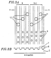
- Figures 3A and 3B show a conventional optical disk, where three guide grooves 7 are individually formed in a spiral shape, and groups of pits 9 are formed on respective lands 8 between the adjacent guide grooves 7 .
- the pit-formation area an area of the surface of the optical disk where the groups of pits 9 are collectively formed.
- the amounts of reflected light from all of the light beams 10 are varied by the pits 9 . This causes noise, interrupting correct counting of the number of guide grooves 7 or lands 8 crossed by the light beam 10 , and as a result high-speed and precise accessing is not possible
- Figures 4A and 4B show an alternative example of the optical disk of Figures 2A and 2F according to the present invention.
- the width of the portions of the guide grooves 7 located in the pit-formation area is reduced.
- positional information is reproduced by detecting a variation in the amount of reflected light from a light beam when it passes a pit. Since the width of the lands 8 of the optical disk of Figures 2A and 2B is uniform, increasing the size of the pits 9 is limited. On the contrary, in the optical disk of Figures 4A and 4B , since the width of the lands 8 is larger in the pit-formation area, the size of the pits 9 can be increased. As a result, the variation in the amount of reflected light becomes greater, and thus stable positional information can be obtained.
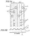
- Figures 5A and 5B show another alternative example of the optical disk of Figures 2A and 2B according to the present invention.
- the width of lands 12 separating the adjacent tracks is made smaller than that of the lands 8 constituting the tracks.
- guide grooves of an optical disk are formed by a laser cutting method.
- the two guide grooves 7 and the group of pits 9 constituting each track are formed by irradiating the optical disk with three argon lasers simultaneously, so as to form a succession of tracks of a spiral shape.
- the optical disk may be irradiated with two argon lasers simultaneously, so as to form one spiral guide groove and a group of pits on every track.
- the two guide grooves 7 and the group of pits 9 constituting each track are formed by irradiating the optical disk with three argon lasers simultaneously, so as to form a succession of tracks of a spiral shape keeping a predetermined fixed distance between the adjacent tracks.
- Figures 6A and 6B show an alternative example of the optical disk of Figures 5A and 5B according to the present invention.
- the width of the portions of the guide grooves 7 located in the pit-formation area is reduced. Accordingly, in this example, as in the example of Figures 4A and 4B , stable positional information can be obtained.
- Figures 7A and 7B show another example of the optical disk according to the present invention.
- five light beams 13 or 14 are used for the recording, reproduction, and deletion of information.
- cne track includes three guide grooves 7 and two lands 8 one of which has a group of pits 9 formed thereon.
- the width of lands 12 separating the adjacent tracks is made smaller than that of the lands 8 constituting the tracks.
- the optical disk of this example is based on the structure of the optical disk of Figures 6A and 6B .
- the structures of Figures 2A and 2B , 4A and 4B , and 5A and 5B can also be used for the realization of optical disks using five light beams. Since the optical disk of Figures 7A and 7B has one additional land 8 having no pits, more precise accessing is possible compared with the optical disk of Figures 6A and 6B .
- Figures 8A and 8B show an alternative example of the optical disk of Figures 7A and 7B .
- two groups of pits 9 are formed on the two lands 8 constituting each track.
- Units of information produced by the two groups of pits 9 formed on the two lands 8 are preferably identical to each other.
- the precision of the accessing is in the same level as that obtained by the optical disk of Figures 6A and 6B .
- more precise positional information can be obtained by using the two light beams passing the two lands 8 having the pits 9 .
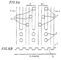
- Figures 9A and 9B are a plan view and a sectional view, respectively, of yet another example of the optical disk according to the present invention.
- two tracks, Nth and (N+1)th tracks (N is a natural number) are shown together with light beams 10 and 11 positioned on the respective tracks.
- Each of the tracks includes two guide grooves 7 , a land 8 interposed between the guide grooves 7 , and a group of pits 9 formed in line with one of the guide grooves 7 .
- three light beams are used.
- the guide grooves 7 and the land 8 have substantially the same width.
- the difference between the widths of the guide grooves 7 and the lands 8 is preferably smaller because, when the difference is greater, the characteristics of the recording, reproduction, and deletion of information of the guide grooves 7 and the lands 8 become different.
- the word "width" used in this context refers to a width of the guide grooves 7 or the lands 8 in areas where the pits 9 are not formed.
- the three light beams 10 are respectively positioned on the two guide grooves 7 and the land 8 constituting the Nth track. A succession of the tracks form a spiral. Thus, when the optical disk rotates once, the light beams 10 on the Nth track move to the (N+1)th track, i.e., the position of the light beams 11 .
- the light beams 11 are continuously moved on the (N+1)th track and the track next thereto.
- the recording, reproduction, or deletion of information is desired at a track other than the track next to the (N+1)th track, the light beams 11 are moved across a track or tracks to a target position where information is to be recorded, reproduced, or deleted, while keeping the positional relationship among the three light beams 11 .
- the two outer light beams among the three light beams 11 necessarily cross two lands 8 .
- light beams move across a track or tracks to reach the Jth track (J is a natural number) from the Nth track they are required to cross 2 x
- a succession of tracks having the two guide grooves 7 and the land 8 running in parallel are formed in a spiral shape. It is also possible to form two spiral guide grooves 7 individually and to form groups of the pits 9 in line with one of the guide grooves 7 , so as to form tracks each composed of two guide grooves 7 and one land 8 .
- Figures 10A and 10B show an alternative example of the optical disk of Figures 9A and 9B .
- the width of lands 12 separating the adjacent tracks is made smaller than that of the lands 8 constituting the tracks.
- guide grooves of an optical disk are formed by a laser cutting method.
- the two guide grooves 7 and the group of pits 9 constituting each track are formed by irradiating the optical disk with two argon lasers simultaneously, so as to form a succession of tracks of a spiral shape.
- the optical disk may be irradiated with one argon laser, so as to form one guide groove and a group of pits in line with every other guide groove to form each.
- the two guide grooves 7 and the group of pits 9 constituting each track are formed by irradiating the optical disk with two argon lasers simultaneously, so as to form a succession of tracks of a spiral shape keeping a fixed distance between the adjacent tracks.
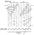
- Figures 11A and 11B show yet another example of the optical disk according to the present invention.
- five light beams 13 or 14 are used for the recording, reproduction, and deletion of information.
- one track includes three guide grooves 7 , two lands 8 , and a group of pits 9 formed in line with one of the three guide grooves 7 . Since the optical disk of Figures 11A and 11B has one additional guide groove 8 having no pits, more precise accessing is possible compared with the optical disk of Figures 9A and 9B .
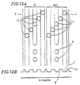
- Figures 12A and 12B show an alternative example of the optical disk of Figures 11A and 11B according to the present invention.
- the width of lands 12 separating the adjacent tracks is made smaller than that of the lands 8 constituting the tracks.
- the recording density cf the optical disk of this example can be further improved compared with the optical disk of Figures 11A and 11B .
- Figures 13A and 13B show an alternative example of the optical disk of Figures 12A and 12B .
- two groups of pits 9 are formed in line with two guide grooves 7 constituting each track.
- Units of information produced by the two groups of pits 9 formed in line with the two guide grooves 7 are preferably identical to each other.
- the precision of the accessing is in the same level as that obtained by the optical disk of Figures 10A and 10B .
- more precise positional information can be obtained by using two light beams among the five light beams passing the two groups of pits 9 .
- the diameter of the pits 9 and the width of the guide grooves 7 are identical to each other.
- the diameter of the pits 9 shculd be optimized corresponding to the diameter of the light beams 10 .
- the diameter of the pits 9 is preferably in the range of 0.3 ⁇ m to 0.5 ⁇ m in order to obtain a large variation in the amount of reflected light.
- Magneto-optical disks according to the above respective examples were manufactured to test the reproduction of pit information and the precision of accessing as follows.
- a magneto-optical disk according to the example of Figures 2A and 2B was manufactured in the following manner.
- a succession of tracks including two guide grooves 7 having a width of 0.7 ⁇ m and a depth of 60 nm and one land 8 were formed on a glass disk substrate at a pitch of 2.8 ⁇ m.
- a group of pits 9 having a diameter of 0.3 ⁇ m and a depth of 60 nm were formed on the land 8 constituting each track.
- the thus-manufactured magneto-optical disk was set in a magneto-optical disk unit capable of conducting the recording, reproduction, and deletion of information using three light beams, and the reproduction of pit information was tested. As a result, a satisfactory pit information sigral was obtained.
- the detection of a variation in the amount of reflected light from the light beams when they cross the lands 8 was ensured by using the total of the amounts of reflected light from the two outer light beams. As a result, the number of lands crossed by the light beams was correctly counted.
- the depths of the guide grooves and the pits were both 60 nm.
- a similar result was obtained when the depth of the pits was made 120 nm while the depth of the guide grooves was 60 nm.
- optimal depths of guide grooves and pits of an optical disk are ⁇ /(8n) and ⁇ /(4n), respectively, wherein ⁇ is the wavelength of a semiconductor laser used for an optical disk unit, and n is the diffractive index of a substrate of the optical disk. This applies to the optical disk according to the present invention.
- a magneto-optical disk according to the example of Figures 4A and 4B was manufactured in the following manner.
- a succession of tracks including two guide grooves 7 having a width of 0.7 ⁇ m and a depth of 60 nm and one land 8 were formed on a glass disk substrate at a pitch of 2.8 ⁇ m.
- the width of the guide grooves 7 was reduced to 0.4 ⁇ m and the width of the lands 8 was increased to 1.0 ⁇ m in the pit-formation area.
- a group of pits 9 having a diameter of 0.4 ⁇ m and a depth of 60 nm were formed on the widened land 8 constituting each track.
- the thus-manufactured magneto-optical disk was set in a magneto-optical disk unit capable of conducting the recording, reproduction, and deletion of information using three light beams, and the reproduction of pit information was tested. As a result, a more satisfactory pit information signal than that obtained by the magneto-optical disk according to the example of Figures 2A and 2B was obtained. Also, the detection of a variation in the amount of reflected light from the light beams when they cross the lands 8 was ensured by using the total of the amounts of reflected light from the two outer light beams. As a result, the number of lands crossed by the light beams was correctly counted.
- the diameter of the light beams is 0.9 ⁇ m
- the diameter of the pits is preferably in the range of 0.3 to 0.5 ⁇ m
- the width of the guide grooves is preferably in the range of 0.3 to 0.6 ⁇ m.
- the diameter of the light beams as used herein refers to a diameter where the intensity of the light beams at the periphery thereof is a half of that at the center thereof.
- a magneto-optical disk according to the example of Figures 5A and 5B was manufactured in the following manner.
- a succession of tracks including two guide grooves 7 having a width of 0.7 ⁇ m and a depth of 60 nm and one land 8 were formed on a glass disk substrate at a pitch of 2.4 ⁇ m.
- a group of pits 9 having a diameter of 0.3 ⁇ m and a depth of 60 nm were formed on the lands 8 constituting each track.
- the thus-manufactured magneto-optical disk was set in a magneto-optical disk unit capable of conducting the recording, reproduction, and deletion of information using three light beams, and the reproduction of pit information was tested. As a result, a satisfactory pit information signal was obtained.
- the detection of a variation in the amount of reflected light from the light beams when they crossed the lands 8 was ensured by using the total of the amounts of reflected light from the two outer light beams.
- the number of lands crossed by the light beams was correctly counted.
- the width of the lands 12 separating the tracks is 0.4 ⁇ m, which is smaller than that of the equivalents of the magneto-optical disk according to the example of Figures 2A and 2B (i.e., 0.7 ⁇ m, which is the same as that of the other lands 8 constituting the tracks). With these narrowed lands 12 , it was possible to improve the recording density of the magneto-optical disk.
- a magneto-optical disk according to the example of Figures 6A and 6B was manufactured in the following manner.
- a succession of tracks including two guide grooves 7 having a width of 0.7 ⁇ m and a depth of 60 nm and one land 8 were formed on a glass disk substrate at a pitch of 2.4 ⁇ m.
- the width of the guide grooves 7 was reduced to 0.4 ⁇ m in the pit-formation area.
- a group of pits 9 having a diameter of 0.4 ⁇ m and a depth of 60 nm were formed on the widened land 8 constituting each track.
- the thus-manufactured magneto-optical disk was set in a magneto-optical disk unit capable of conducting the recording, reproduction, and deletion of information using three light beams, and the reproduction of pit information was tested. As a result, a more satisfactory pit information signal than that obtained by the magneto-optical disk according to the example of Figures 5A and 5B . Also, the detection of a variation in the amount of reflected light from the light beams when they cross the lands 8 was ensured by using the total of the amounts of reflected light from the three light beams. As a result, the number of lands crossed by the light beams was correctly counted.
- a magneto-optical disk according to the example of Figures 7A and 7B was manufactured in the following manner.
- a succession of tracks including three guide grooves 7 having a width of 0.7 ⁇ m and a depth of 60 nm and two lands 8 were formed on a glass disk substrate at a pitch of 3.9 ⁇ m.
- the width of the guide grooves 7 was reduced to 0.4 ⁇ m in the pit-formation area.
- a group of pits 9 having a diameter of 0.4 ⁇ m and a depth of 60 nm were formed on one land 8 constituting each track.
- the thus-manufactured magneto-optical disk was set in a magneto-optical disk unit capable of conducting the recording, reproduction, and deletion of information using five light beams, and the reproduction of pit information was tested. As a result, a satisfactory pit information signal was obtained, and moreover read error of pit information greatly reduced. Also, the detection of a variation in the amount of reflected light from the light beams when they cross the lands 8 was ensured by using the total of the amounts of reflected light from the center and two outermost light beams among the five light beams. As a result, the number of lands crossed by the light beams was correctly counted.
- a magneto-optical disk according to the example of Figures 8A and 8B was manufactured in the following manner.
- a succession of tracks including three guide grooves 7 having a width of 0.7 ⁇ m and a depth of 60 nm and two lands 8 were formed on a glass disk substrate at a pitch of 3.9 ⁇ m.
- the width of the guide grooves 7 was reduced to 0.4 ⁇ m in the pit-formation area.
- Two grcups of pits 9 having a diameter of 0.4 ⁇ m and a depth of 60 nm were formed on the two lands 8 constituting each track.
- the thus-manufactured magneto-optical disk was set in a magneto-optical disk unit capable of conducting the recording, reproduction, and deletion of information using five light beams.
- Two units of pit information produced by the groups of pits on the two lands 8 were reproduced by two light beams passing the two lands 8 , so as to determine positional information from the two units of pit information. As a result, a satisfactory pit information signal was obtained, and read errors of pit information greatly reduced. Also, the detection of a variation in the amount of reflected light from the light beams when they cross the lands 8 was ensured by using the total of the amounts of reflected light from the center and two outermost light beams among the five light beams. As a result, the number of lands crossed by the light beams was correctly counted.
- a magneto-optical disk according to the example of Figures 9A and 9B was manufactured in the following manner.
- a succession of tracks including two guide grooves 7 having a width of 0.7 ⁇ m and a depth of 60 nm and one land 8 were formed on a glass disk substrate at a pitch of 2.8 ⁇ m.
- a group of pits 9 having a diameter of 0.7 ⁇ m and a depth of 60 nm were formed in line with one of the guide grooves 7 constituting each track.
- the thus-manufactured magneto-optical disk was set in a magneto-optical disk unit capable of conducting the recording, reproduction, and deletion of information using three light beams, and the reproduction of pit information was tested. As a result, a satisfactory pit information signal was obtained.
- the diameter of the pits is preferably in the range of 0.3 to 0.5 ⁇ m when the diameter of the light beam is 0.9 ⁇ m.
- a magneto-optical disk according to the example of Figures 10A and 10B was manufactured in the following manner.
- a succession of tracks including two guide grooves 7 having a width of 0.7 ⁇ m and a depth of 60 nm and one land 8 were formed on a glass disk substrate at a pitch of 2.4 ⁇ m.
- a group of pits 9 having a diameter of 0.7 ⁇ m and a depth of 60 nm were formed in line with one of the guide grooves 7 constituting each track.
- the thus-manufactured magneto-optical disk was set in a magneto-optical disk unit capable of conducting the recording, reproduction, and deletion of information using three light beams, and the reproduction of pit information was tested. As a result, a satisfactory pit information signal was obtained.
- the detection of a variation in the amount of reflected light from the light beams when they cross the lands 8 was ensured by using the total of the amounts of reflected light from the two outer beams. As a result, the number of lands crossed by the light beams was correctly counted.
- the width is smaller than that of the equivalents of the magneto-optical disk according to Figures 9A and 9B , i.e., 0.7 ⁇ m, which is the same as that of the other lands 8 constituting the tracks.
- the width of the lands separating the tracks was 0.4 ⁇ m, it was possible to improve the recording density of the magneto-optical disk.
- a magneto-optical disk according to the example of Figures 11A and 11B was manufactured in the following manner.
- a succession of tracks including three guide grooves 7 having a width of 0.7 ⁇ m and a depth of 60 nm and two lands 8 were formed on a glass disk substrate at a pitch of 4.2 ⁇ m.
- a group of pits 9 having a diameter of 0.7 ⁇ m and a depth of 60 nm were formed in line with one of the guide grooves 7 constituting each track.
- the thus-manufactured magneto-optical disk was set in a magneto-optical disk unit capable of conducting the recording, reproduction, and deletion of information using five light beams, and the reproduction of pit information was tested. As a result, a satisfactory pit information signal was obtained.
- a magneto-optical disk according to the example of Figures 12A and 12B was manufactured in the following manner.
- a succession of tracks including three guide grooves 7 having a width of 0.7 ⁇ m and a depth of 60 nm and two lands 8 were formed on a glass disk substrate at a pitch of 3.9 ⁇ m.
- a group of pits 9 having a diameter of 0.7 ⁇ m and a depth of 60 nm were formed in line with one of the guide grooves 7 constituting each track.
- the thus-manufactured magneto-optical disk was set in a magneto-optical disk unit capable of conducting the recording, reproduction, and deletion of information using five light beams, and the reproduction of pit information was tested. As a result, a satisfactory pit information signal was obtained.
- the detection of a variation in the amount of reflected light from the five light beams when they cross the lands 8 was ensured by using the total of the amounts of reflected light from the center and two outermost light beams among the five light beams.
- the number of lands crossed by the light beams was correctly counted.
- the width of the lands 12 separating the tracks is 0.4 ⁇ m which is smaller than that of the equivalents of the magneto-optical disk according to the example of Figures 11A and 11B (i.e., 0.7 ⁇ m, which is the same as that of the other lands 8 constituting the tracks). With these narrowed lands 12 , it was possible to improve the recording density of the magneto-optical disk.
- a magneto-optical disk according to the example of Figures 13A and 13B was manufactured in the following manner.
- a succession of tracks including three guide grooves 7 having a width of 0.7 ⁇ m and a depth of 60 nm and two lands 8 were formed on a glass disk substrate at a pitch of 3.9 ⁇ m.
- Groups of pits 9 having a diameter of 0.7 ⁇ m and a depth of 60 nm were formed in line with two guide grooves 7 constituting each track.
- the thus-manufactured magneto-optical disk was set in a magneto-optical disk unit capable of conducting the recording, reproduction, and deletion of information using five light beams.
- Two units of pit information produced by the groups of pits 9 formed in line with the two guide grooves 7 were reproduced by two light beams passing the two guide grooves 7 , so as to determine positional information from the two units of pit information.
- a satisfactory pit informaticn signal was obtained, and read errors of pit information greatly reduced.
- the detection of a variation in the amount of reflected light from the light beams when they cross the lands 8 was ensured by using the total of the amounts of reflected light from the center and two outermost light beams among the five light beams. As a result, the number of lands crossed by the light beams was correctly counted.
Landscapes
- Physics & Mathematics (AREA)
- Optics & Photonics (AREA)
- Optical Recording Or Reproduction (AREA)
- Optical Record Carriers And Manufacture Thereof (AREA)
Claims (16)
- Optischer Aufzeichnungsträger (1, 2) mit mehreren Informationsaufzeichnungsspuren (N, N+1) mit jeweils M Führungsrillen (7), wobei M eine ganze Zahl vom Wert 2 oder größer ist, und mit M-1 erhabenen Bereichen (oder einem erhabenen Bereich) (8), die zwischen benachbarten Führungsrillen eingefügt sind, wobei Adresseninformation in Form von Vertiefungen (9) vorhanden ist, die im erhabenen Bereich oder mindestens einem der erhabenen Bereiche oder in einer Linie mit mindestens einer der Führungsrillen jeder der Spuren ausgebildet sind, wobei der Träger zum Aufzeichnen, Abspielen und Löschen von Information in den Führungsrillen und den erhabenen Bereichen der Spuren durch jeweilige auf ihn projizierte Lichtstrahlen (10) ausgebildet ist, wobei in jeder Spur oder in Zuordnung zu dieser ein erhabener Bereich vorhanden ist, wenn die Adresseninformations-Vertiefungen in mindestens einem der erhabenen Bereiche ausgebildet sind, oder eine Führungsrille vorhanden ist, wenn die Adresseninformations-Vertiefungen in einer Linie mit mindestens einer der Führungsrillen ausgebildet sind, die keine Adresseninformations-Vertiefungen enthält, um genaues Zählen von Spuren zu erleichtern, die in Querrichtung durch die im Gebrauch auf den Träger gestrahlten Lichtstrahlen überquert werden.
- Optischer Auf zeichnungsträger nach Anspruch 1 in Form einer optischen Platte, bei der die Adresseninformations-Vertiefungen (9) im erhabenen Bereich oder mindestens einem der erhabenen Bereiche (8) jeder der Spuren ausgebildet sind und in jeder Spur oder in Zuordnung zu dieser ein erhabener Bereich ohne die Adresseninformations-Vertiefungen vorhanden ist.
- Optischer Aufzeichnungsträger nach Anspruch 2, bei dem ein erhabener Bereich ohne Adresseninformation in jeder Spur vorhanden ist.
- Optischer Auf zeichnungsträger nach Anspruch 2 oder 3, bei dem der erhabene Bereich (12) ohne Adresseninformations-Vertiefungen zwischen benachbarten Spuren liegt.
- Optischer Aufzeichnungsträger nach einem der Ansprüche 2 bis 4, bei dem die Führungsrillen und die erhabenen Bereiche im Wesentlichen dieselbe Breite aufweisen.
- Optischer Aufzeichnungsträger nach Anspruch 4, bei dem der erhabene Bereich (12) ohne Adresseninformations-Vertiefungen, der zwischen benachbarten Spuren liegt, eine Breite aufweist, die kleiner als die der in den Spuren liegenden erhabenen Bereiche ist.
- Optischer Aufzeichnungsträger nach einem der Ansprüche 2 bis 6, bei dem ein Gebiet jedes erhabenen Bereichs mit Adresseninformations-Vertiefungen, in dem die Vertiefungen ausgebildet sind, eine größere Breite als das restliche Gebiet des erhabenen Bereichs aufweist, in dem die Vertiefungen nicht vorhanden sind.
- Optischer Aufzeichnungsträger nach Anspruch 1 in Form einer optischen Platte, bei der die Adresseninformations-Vertiefungen in einer Linie mit mindestens einer der in jeder der Spuren liegenden Führungsrillen ausgebildet sind und bei der jede Spur eine Führungsrille ist, die keine Adresseninformations-Vertiefungen in einer Linie mit ihr aufweist.
- Optischer Aufzeichnungsträger nach Anspruch 8, bei den die Führungsrillen und die erhabenen Bereiche in Wesentlichen dieselbe Breite aufweisen.
- Optischer Aufzeichnungsträger nach Anspruch 8, bei den ein zwischen benachbarten Spuren liegender erhabener Bereich eine kleinere Breite als ein erhabener Bereich oder erhabene Bereiche aufweist, die in jeder der Spuren liegen.
- Optischer Aufzeichnungsträger nach Anspruch 9 oder Anspruch 10, bei dem jede der Spuren drei Führungsrillen und zwei erhabene Bereiche aufweist, die zwischen benachbarte Führungsrillen eingefügt sind, und die Adresseninfornations-Vertiefungen in einer Linie mit derjenigen der drei Führungsrillen ausgebildet sind, die in der Mitte liegt.
- Optischer Aufzeichnungsträger nach einen der Ansprüche 8 bis 11, bei dem der Durchmesser der Adresseninfornations-Vertiefungen kleiner als die Breite der Führungsrillen ist, mit der die Vertiefungen in einer Linie liegen.
- Optischer Auf zeichnungsträger nach einen der Ansprüche 2 bis 12, bei dem die mehreren Informationsaufzeichnungsspuren aufeinanderfolgende Windungen einer Spirale oder konzentrische Kreise bilden.
- Optischer Aufzeichnungsträger nach einen der vorstehenden Ansprüche in Form eines magnetooptischen Aufzeichnungsträgers.
- Optischer Aufzeichnungsträger nach einen der vorstehenden Ansprüche, auf den unter Verwendung von 2M-1 Lichtstrahlen, die auf die jeweiligen Führungsrillen und den erhabenen Bereich (die erhabenen Bereiche) fokussiert werden, Information aufgezeichnet oder von ihm abgespielt oder auf ihn gelöscht werden kann.
- Verfahren zum Aufzeichnen, Abspielen und Löschen von Information auf und von einer optischen Platte nach einem der vorstehenden Ansprüche, mit dem Schritt des gleichzeitigen Fokussierens von Lichtstrahlen auf die jeweiligen Führungsrillen und den erhabenen Bereich (die erhabenen Bereiche) der Spuren, um das Aufzeichnen, Abspielen und Löschen von Information zu bewerkstelligen.
Applications Claiming Priority (6)
| Application Number | Priority Date | Filing Date | Title |
|---|---|---|---|
| JP286478/93 | 1993-11-16 | ||
| JP286479/93 | 1993-11-16 | ||
| JP5286478A JP2923185B2 (ja) | 1993-11-16 | 1993-11-16 | 光ディスク基板 |
| JP28647993 | 1993-11-16 | ||
| JP5286479A JP2834991B2 (ja) | 1993-11-16 | 1993-11-16 | 光ディスク記録再生消去方法及び光ディスク基板 |
| JP28647893 | 1993-11-16 |
Publications (2)
| Publication Number | Publication Date |
|---|---|
| EP0653748A1 EP0653748A1 (de) | 1995-05-17 |
| EP0653748B1 true EP0653748B1 (de) | 2000-07-05 |
Family
ID=26556338
Family Applications (1)
| Application Number | Title | Priority Date | Filing Date |
|---|---|---|---|
| EP94308481A Expired - Lifetime EP0653748B1 (de) | 1993-11-16 | 1994-11-16 | Optische Platte und Verfahren zur Aufzeichnung, Wiedergabe und Löschen auf und von einer optischen Platte |
Country Status (3)
| Country | Link |
|---|---|
| US (1) | US5600627A (de) |
| EP (1) | EP0653748B1 (de) |
| DE (1) | DE69425108T2 (de) |
Families Citing this family (3)
| Publication number | Priority date | Publication date | Assignee | Title |
|---|---|---|---|---|
| US6487151B1 (en) | 1994-12-20 | 2002-11-26 | Matsushita Electric Industrial Co. Ltd. | Optical information recording and reproducing system with overwrite capability and recording medium for use therewith |
| JP2000011460A (ja) * | 1998-06-22 | 2000-01-14 | Pioneer Electron Corp | 光ディスク |
| JP2005129108A (ja) * | 2003-10-22 | 2005-05-19 | Fuji Photo Film Co Ltd | 光情報記録媒体 |
Family Cites Families (11)
| Publication number | Priority date | Publication date | Assignee | Title |
|---|---|---|---|---|
| EP0261608A3 (en) * | 1986-09-20 | 1990-05-30 | Csk Corporation | Optical recording medium |
| JP2548186B2 (ja) * | 1987-04-13 | 1996-10-30 | パイオニア株式会社 | 案内溝付光デイスク |
| US5185730A (en) * | 1989-06-01 | 1993-02-09 | Pioneer Electronic Corporation | Method for reading data from optical disk |
| JP2830278B2 (ja) * | 1990-01-19 | 1998-12-02 | ソニー株式会社 | ディスク式記録再生装置 |
| JPH0427610A (ja) * | 1990-05-22 | 1992-01-30 | Daihatsu Motor Co Ltd | 後輪懸架装置 |
| JPH04149834A (ja) * | 1990-10-12 | 1992-05-22 | Pioneer Electron Corp | 相変化型光学式情報記録媒体 |
| JPH056590A (ja) * | 1991-06-28 | 1993-01-14 | Toshiba Corp | 光磁気記録装置 |
| JP3093364B2 (ja) * | 1991-10-14 | 2000-10-03 | パイオニア株式会社 | 光学式記録媒体及びその再生装置 |
| US5402411A (en) * | 1992-03-05 | 1995-03-28 | Fujitsu Limited | Constant amplitude of tracking error signals generated from a head guide track and a performed track |
| JP2868682B2 (ja) * | 1992-05-15 | 1999-03-10 | シャープ株式会社 | 光ディスク |
| JP3221100B2 (ja) * | 1992-10-30 | 2001-10-22 | ソニー株式会社 | 光ディスク |
-
1994
- 1994-11-14 US US08/340,333 patent/US5600627A/en not_active Expired - Lifetime
- 1994-11-16 EP EP94308481A patent/EP0653748B1/de not_active Expired - Lifetime
- 1994-11-16 DE DE69425108T patent/DE69425108T2/de not_active Expired - Fee Related
Also Published As
| Publication number | Publication date |
|---|---|
| US5600627A (en) | 1997-02-04 |
| DE69425108T2 (de) | 2001-03-22 |
| DE69425108D1 (de) | 2000-08-10 |
| EP0653748A1 (de) | 1995-05-17 |
Similar Documents
| Publication | Publication Date | Title |
|---|---|---|
| JP3268126B2 (ja) | 光記録媒体 | |
| US6985427B2 (en) | Multi-layered optical disk and method of detecting a track | |
| KR100454452B1 (ko) | 광학정보기록/판독매체및기록방법 | |
| US6487164B1 (en) | Optical recording medium capable of assuring sufficient levels of signals required for reading/writing data, and stamper for manufacture of the same | |
| JPH0481816B2 (de) | ||
| JPH04149834A (ja) | 相変化型光学式情報記録媒体 | |
| US5600627A (en) | Optical disk and a method for recording, reproducing, and deleting information on and from the optical disk | |
| US6014363A (en) | Phase change optical disk medium | |
| JP3313961B2 (ja) | 光記録媒体と記録方法 | |
| JP2834991B2 (ja) | 光ディスク記録再生消去方法及び光ディスク基板 | |
| JP2923185B2 (ja) | 光ディスク基板 | |
| EP1063642B1 (de) | Optisches Aufzeichnungsmedium | |
| JPS60121553A (ja) | 光記録ディスク | |
| JPH01171136A (ja) | 光メモリ素子用基板 | |
| JP3455149B2 (ja) | 光記録媒体のアドレス管理方法 | |
| JPH0235637A (ja) | 光情報記録媒体 | |
| JP3184025B2 (ja) | 光ディスク装置及び光ディスク | |
| JPH04102230A (ja) | 光記録媒体及びこれを使用する記録再生方法 | |
| JPS63119033A (ja) | 情報記録媒体 | |
| JPH07334868A (ja) | 情報記憶媒体 | |
| JPH04162223A (ja) | 光情報記録媒体 | |
| JPH06333237A (ja) | 光学情報記録媒体及び光学情報の記録・消去・再生方法 | |
| JPH03122820A (ja) | 光ディスク | |
| JPH09106548A (ja) | ディスク状光学記録媒体 | |
| JPS5897146A (ja) | 光学デイスク |
Legal Events
| Date | Code | Title | Description |
|---|---|---|---|
| PUAI | Public reference made under article 153(3) epc to a published international application that has entered the european phase |
Free format text: ORIGINAL CODE: 0009012 |
|
| AK | Designated contracting states |
Kind code of ref document: A1 Designated state(s): DE FR GB |
|
| 17P | Request for examination filed |
Effective date: 19950804 |
|
| 17Q | First examination report despatched |
Effective date: 19980623 |
|
| GRAG | Despatch of communication of intention to grant |
Free format text: ORIGINAL CODE: EPIDOS AGRA |
|
| GRAG | Despatch of communication of intention to grant |
Free format text: ORIGINAL CODE: EPIDOS AGRA |
|
| GRAH | Despatch of communication of intention to grant a patent |
Free format text: ORIGINAL CODE: EPIDOS IGRA |
|
| GRAH | Despatch of communication of intention to grant a patent |
Free format text: ORIGINAL CODE: EPIDOS IGRA |
|
| GRAA | (expected) grant |
Free format text: ORIGINAL CODE: 0009210 |
|
| AK | Designated contracting states |
Kind code of ref document: B1 Designated state(s): DE FR GB |
|
| REF | Corresponds to: |
Ref document number: 69425108 Country of ref document: DE Date of ref document: 20000810 |
|
| ET | Fr: translation filed | ||
| PLBE | No opposition filed within time limit |
Free format text: ORIGINAL CODE: 0009261 |
|
| STAA | Information on the status of an ep patent application or granted ep patent |
Free format text: STATUS: NO OPPOSITION FILED WITHIN TIME LIMIT |
|
| 26N | No opposition filed | ||
| REG | Reference to a national code |
Ref country code: GB Ref legal event code: IF02 |
|
| PGFP | Annual fee paid to national office [announced via postgrant information from national office to epo] |
Ref country code: FR Payment date: 20021108 Year of fee payment: 9 |
|
| PGFP | Annual fee paid to national office [announced via postgrant information from national office to epo] |
Ref country code: GB Payment date: 20021113 Year of fee payment: 9 |
|
| PGFP | Annual fee paid to national office [announced via postgrant information from national office to epo] |
Ref country code: DE Payment date: 20021121 Year of fee payment: 9 |
|
| PG25 | Lapsed in a contracting state [announced via postgrant information from national office to epo] |
Ref country code: GB Free format text: LAPSE BECAUSE OF NON-PAYMENT OF DUE FEES Effective date: 20031116 |
|
| PG25 | Lapsed in a contracting state [announced via postgrant information from national office to epo] |
Ref country code: DE Free format text: LAPSE BECAUSE OF NON-PAYMENT OF DUE FEES Effective date: 20040602 |
|
| GBPC | Gb: european patent ceased through non-payment of renewal fee |
Effective date: 20031116 |
|
| PG25 | Lapsed in a contracting state [announced via postgrant information from national office to epo] |
Ref country code: FR Free format text: LAPSE BECAUSE OF NON-PAYMENT OF DUE FEES Effective date: 20040730 |
|
| REG | Reference to a national code |
Ref country code: FR Ref legal event code: ST |