EP0653749A2 - Optisches Informationsaufzeichnungs-/wiedergabegerät und -verfahren mit einer Funktion zur Einstellung der Wiedergabeleistung - Google Patents
Optisches Informationsaufzeichnungs-/wiedergabegerät und -verfahren mit einer Funktion zur Einstellung der Wiedergabeleistung Download PDFInfo
- Publication number
- EP0653749A2 EP0653749A2 EP94308432A EP94308432A EP0653749A2 EP 0653749 A2 EP0653749 A2 EP 0653749A2 EP 94308432 A EP94308432 A EP 94308432A EP 94308432 A EP94308432 A EP 94308432A EP 0653749 A2 EP0653749 A2 EP 0653749A2
- Authority
- EP
- European Patent Office
- Prior art keywords
- reproducing
- information
- recording
- medium
- layer
- Prior art date
- Legal status (The legal status is an assumption and is not a legal conclusion. Google has not performed a legal analysis and makes no representation as to the accuracy of the status listed.)
- Granted
Links
- 230000003287 optical effect Effects 0.000 title claims abstract description 38
- 238000000034 method Methods 0.000 title claims description 35
- 230000005415 magnetization Effects 0.000 claims abstract description 35
- 230000005855 radiation Effects 0.000 claims 4
- 230000001678 irradiating effect Effects 0.000 claims 2
- 239000010410 layer Substances 0.000 description 66
- 238000012360 testing method Methods 0.000 description 22
- 230000000694 effects Effects 0.000 description 15
- 238000009826 distribution Methods 0.000 description 11
- 238000010586 diagram Methods 0.000 description 9
- 238000005259 measurement Methods 0.000 description 6
- 230000008878 coupling Effects 0.000 description 5
- 238000010168 coupling process Methods 0.000 description 5
- 238000005859 coupling reaction Methods 0.000 description 5
- 230000007423 decrease Effects 0.000 description 5
- 239000011229 interlayer Substances 0.000 description 5
- 239000000758 substrate Substances 0.000 description 5
- 230000004304 visual acuity Effects 0.000 description 5
- 230000005374 Kerr effect Effects 0.000 description 3
- 238000004364 calculation method Methods 0.000 description 3
- 238000006243 chemical reaction Methods 0.000 description 3
- 238000010276 construction Methods 0.000 description 3
- 230000005381 magnetic domain Effects 0.000 description 3
- 238000001514 detection method Methods 0.000 description 2
- 238000003780 insertion Methods 0.000 description 2
- 230000037431 insertion Effects 0.000 description 2
- 230000003993 interaction Effects 0.000 description 2
- 239000000463 material Substances 0.000 description 2
- 238000012544 monitoring process Methods 0.000 description 2
- 238000012545 processing Methods 0.000 description 2
- 239000011241 protective layer Substances 0.000 description 2
- 230000009467 reduction Effects 0.000 description 2
- 230000004044 response Effects 0.000 description 2
- 238000013459 approach Methods 0.000 description 1
- 230000008859 change Effects 0.000 description 1
- 238000013500 data storage Methods 0.000 description 1
- 230000003247 decreasing effect Effects 0.000 description 1
- 239000011521 glass Substances 0.000 description 1
- 239000000696 magnetic material Substances 0.000 description 1
- 229920000515 polycarbonate Polymers 0.000 description 1
- 239000004417 polycarbonate Substances 0.000 description 1
- 238000012546 transfer Methods 0.000 description 1
- 239000012780 transparent material Substances 0.000 description 1
Images


Classifications
-
- G—PHYSICS
- G11—INFORMATION STORAGE
- G11B—INFORMATION STORAGE BASED ON RELATIVE MOVEMENT BETWEEN RECORD CARRIER AND TRANSDUCER
- G11B7/00—Recording or reproducing by optical means, e.g. recording using a thermal beam of optical radiation by modifying optical properties or the physical structure, reproducing using an optical beam at lower power by sensing optical properties; Record carriers therefor
-
- G—PHYSICS
- G11—INFORMATION STORAGE
- G11B—INFORMATION STORAGE BASED ON RELATIVE MOVEMENT BETWEEN RECORD CARRIER AND TRANSDUCER
- G11B11/00—Recording on or reproducing from the same record carrier wherein for these two operations the methods are covered by different main groups of groups G11B3/00 - G11B7/00 or by different subgroups of group G11B9/00; Record carriers therefor
- G11B11/10—Recording on or reproducing from the same record carrier wherein for these two operations the methods are covered by different main groups of groups G11B3/00 - G11B7/00 or by different subgroups of group G11B9/00; Record carriers therefor using recording by magnetic means or other means for magnetisation or demagnetisation of a record carrier, e.g. light induced spin magnetisation; Demagnetisation by thermal or stress means in the presence or not of an orienting magnetic field
- G11B11/105—Recording on or reproducing from the same record carrier wherein for these two operations the methods are covered by different main groups of groups G11B3/00 - G11B7/00 or by different subgroups of group G11B9/00; Record carriers therefor using recording by magnetic means or other means for magnetisation or demagnetisation of a record carrier, e.g. light induced spin magnetisation; Demagnetisation by thermal or stress means in the presence or not of an orienting magnetic field using a beam of light or a magnetic field for recording by change of magnetisation and a beam of light for reproducing, i.e. magneto-optical, e.g. light-induced thermomagnetic recording, spin magnetisation recording, Kerr or Faraday effect reproducing
- G11B11/10502—Recording on or reproducing from the same record carrier wherein for these two operations the methods are covered by different main groups of groups G11B3/00 - G11B7/00 or by different subgroups of group G11B9/00; Record carriers therefor using recording by magnetic means or other means for magnetisation or demagnetisation of a record carrier, e.g. light induced spin magnetisation; Demagnetisation by thermal or stress means in the presence or not of an orienting magnetic field using a beam of light or a magnetic field for recording by change of magnetisation and a beam of light for reproducing, i.e. magneto-optical, e.g. light-induced thermomagnetic recording, spin magnetisation recording, Kerr or Faraday effect reproducing characterised by the transducing operation to be executed
- G11B11/10515—Reproducing
-
- G—PHYSICS
- G11—INFORMATION STORAGE
- G11B—INFORMATION STORAGE BASED ON RELATIVE MOVEMENT BETWEEN RECORD CARRIER AND TRANSDUCER
- G11B11/00—Recording on or reproducing from the same record carrier wherein for these two operations the methods are covered by different main groups of groups G11B3/00 - G11B7/00 or by different subgroups of group G11B9/00; Record carriers therefor
- G11B11/10—Recording on or reproducing from the same record carrier wherein for these two operations the methods are covered by different main groups of groups G11B3/00 - G11B7/00 or by different subgroups of group G11B9/00; Record carriers therefor using recording by magnetic means or other means for magnetisation or demagnetisation of a record carrier, e.g. light induced spin magnetisation; Demagnetisation by thermal or stress means in the presence or not of an orienting magnetic field
- G11B11/105—Recording on or reproducing from the same record carrier wherein for these two operations the methods are covered by different main groups of groups G11B3/00 - G11B7/00 or by different subgroups of group G11B9/00; Record carriers therefor using recording by magnetic means or other means for magnetisation or demagnetisation of a record carrier, e.g. light induced spin magnetisation; Demagnetisation by thermal or stress means in the presence or not of an orienting magnetic field using a beam of light or a magnetic field for recording by change of magnetisation and a beam of light for reproducing, i.e. magneto-optical, e.g. light-induced thermomagnetic recording, spin magnetisation recording, Kerr or Faraday effect reproducing
- G11B11/10595—Control of operating function
Definitions
- the present invention relates to an optical information recording/reproducing apparatus and method and, more particularly, to an optical information recording/reproducing apparatus and method of performing at least one of recording and reproduction of information by using a magnetooptical interaction.
- FIG. 1A shows the section of an optical disc as one example of the super-resolving technique.
- a substrate 20 is usually constructed of a transparent material such as glass or polycarbonate.
- An enhance layer 21, a reproducing layer 22, a recording layer 23, and a protective layer 24 are stacked in this order on the substrate 20.
- the arrows in the magnetic materials indicate the directions of magnetization in the films.
- the recording layer 23 is a film made of a material, such as TbFeCo or DyFeCo, having a high perpendicular magnetic anisotropy. Recording information is held in accordance with whether the magnetic domain in this layer is directed upward or downward.
- the reproducing layer 22 is constructed of a material with a large saturation magnetization Ms and a small perpendicular magnetic anisotropy. Although the reproducing layer 22 is a longitudinal magnetization film at room temperature, it becomes a perpendicular magnetization film when a predetermined temperature Tth is reached, since the saturation magnetization Ms decreases.
- a temperature gradient as in Fig. 1C is obtained in the center of a data track.
- the isotherm of the predetermined temperature Tth is present within a spot as illustrated in Fig. 1B. Therefore, the reproducing layer 22 dose not contribute to the polar Kerr effect since the layer becomes a longitudinal magnetization film at the predetermined temperature Tth or lower as discussed above. Consequently, the information in the recording layer 23 is masked and therefore cannot be seen from the reproducing beam.
- a portion of the reproducing layer 22, that is at the predetermined temperature Tth or higher, is a perpendicular magnetization film.
- the direction of magnetization of this portion is the same as that of the recording information due to exchange coupling from the recording layer 23.
- the information in the recording layer 23 is transferred only to an aperture which is smaller than the spot, thereby effectuating super resolution.
- a construction of this sort is called RAD (Rear Aperture Detection) because an aperture is formed on the rear side with respect to the direction in which the spot travels on the disc.
- Figs. 2A to 2C illustrate an example of an arrangement of FAD (Front Aperture Detection) in which an aperture is formed on the front side with respect to the spot travelling direction.
- a reproducing layer 22 in this arrangement is weaker in longitudinal anisotropy than that of RAD. Therefore, at room temperature magnetic domains in a recording layer 23 are transferred to the reproducing layer 22 through an interlayer 25 due to exchange coupling.
- the Curie temperature of the interlayer 25 is set at about 100°C. Since the exchange coupling disappears when the medium reaches the Curie temperature of the interlayer 25 upon being heated by a reproducing beam, the direction of magnetization in the reproducing layer 22 becomes longitudinal.
- the Curie temperature of the interlayer 25 By setting the Curie temperature of the interlayer 25 at a predetermined temperature Tth, therefore, the magnetic domains in the recording layer 23 are transferred only on the front side of a spot, which is bounded by the isotherm of the predetermined temperature Tth as in Fig. 2B, realizing super resolution.
- a construction as shown in Figs. 3A to 3C is also proposed as another method of super resolution.
- a reproducing layer 22, Fig. 3A is a perpendicular magnetization film with a low coercive force. Therefore, upon application of an initializing magnetic field Hb at room temperature, the directions of magnetization in the reproducing layer 22 are aligned in the direction of the initializing magnetic field regardless of the magnetization direction of a recording layer 23. That is, a domain wall is produced in a portion where the magnetization direction of the recording layer 22 is opposite to the direction of the initializing magnetic field.
- a reproducing beam is irradiated while applying a reproducing magnetic field Hr in a direction opposite to the direction of the initializing magnetic field.
- the magnitude of the reproducing magnetic field is set such that in a low-temperature portion in a spot of the reproducing beam, the coercive force of the reproducing layer 22 is higher than the energy which reverses the magnetization of the reproducing layer 22 by using an exchange coupling force from the recording layer 23 and the reproducing magnetic field. That is, in the low-temperature portion the magnetization of the reproducing layer 22 points in the direction of the initializing magnetic field. Therefore, the magnetization of the recording layer 23 is masked and hence does not contribute to signal reproduction.
- an interlayer is sometimes formed between the reproducing layer 22 and the recording layer 23 in order to control the energy of a domain wall.
- this arrangement is identical in principle with that shown in Figs. 3A to 3C.
- the present invention has been made in consideration of the above conventional problems and has as its object to provide an optical information recording/reproducing apparatus and method which has solved the above problems.
- the above object is achieved by an optical information recording/reproducing apparatus in which, while a magnetooptical recording medium formed by stacking at least a recording layer, which consists of a perpendicular magnetization film for magnetically holding information, and a reproducing layer whose magnetic coupled state with the recording layer changes in accordance with a temperature is rotated at a fixed angular velocity, a laser beam is irradiated onto the medium from the reproducing layer, thereby reproducing information held by the recording layer by transferring the information to the reproducing layer, the recording medium including a plurality of tracks and being divided into a plurality of zones, comprising: determining means for determining an optimum intensity of the laser beam in reproduction by using a buffer zone provided between the zones of the recording medium; and adjusting means for adjusting the intensity of the laser beam in reproduction of the information in accordance with the determined optimum intensity.
- an optical information recording/reproducing apparatus in which, while a magnetooptical recording medium formed by stacking at least a recording layer, which consists of a perpendicular magnetization film for magnetically holding information, and a reproducing layer whose magnetic coupled state with the recording layer changes in accordance with a temperature is rotated at a fixed angular velocity, a laser beam is irradiated onto the medium from the reproducing layer, thereby reproducing information held by the recording layer by transferring the information to the reproducing layer, the recording medium including a plurality of tracks and being divided into a plurality of zones, comprising: determining means for determining an optimum intensity of the laser beam in reproduction by using a zone including one or more tracks including an innermost or outermost track of each of the zones of the recording medium; and adjusting means for adjusting the intensity of the laser beam in reproduction of the information in accordance with the determined optimum intensity.
- the above object is achieved by an optical information recording/reproducing method in which, while a magnetooptical recording medium formed by stacking at least a recording layer, which consists of a perpendicular magnetization film for magnetically holding information, and a reproducing layer whose magnetic coupled state with the recording layer changes in accordance with a temperature is rotated at a fixed angular velocity, a laser beam is irradiated onto the medium from the reproducing layer, thereby reproducing information held by the recording layer by transferring the information to the reproducing layer, the recording medium including a plurality of tracks and being divided into a plurality of zones, comprising the steps of: determining an optimum intensity of the laser beam in reproduction by using a buffer zone provided between the zones of the recording medium; and adjusting the intensity of the laser beam in reproduction of the information in accordance with the determined optimum intensity.
- the above object is achieved by an optical information recording/reproducing method in which, while a magnetooptical recording medium formed by stacking at least a recording layer, which consists of a perpendicular magnetization film for magnetically holding information, and a reproducing layer whose magnetic coupled state with the recording layer changes in accordance with a temperature is rotated at a fixed angular velocity, a laser beam is irradiated onto the medium from the reproducing layer, thereby reproducing information held by the recording layer by transferring the information to the reproducing layer, the recording medium including a plurality of tracks and being divided into a plurality of zones, comprising the steps of: determining an optimum intensity of the laser beam in reproduction by using a zone including one or more tracks including an innermost or outermost track of each of the zones of the recording medium; and adjusting the intensity of the laser beam in reproduction of the information in accordance with the determined optimum intensity.
- Fig. 7 is a block diagram for explaining the first embodiment of the present invention.
- an apparatus of this embodiment includes a CPU 1, D/A converters 2 and 3, a switch 4, a laser driver circuit 5, an information recording/reproducing head 6, a preamplifier 7, an optical disc 10, and a spindle motor 11.
- the CPU 1 sets data corresponding to optimum reproducing power, which is determined in accordance with the procedure to be described later, in the reproducing power setting D/A converter 3.
- the CPU 1 then drives the laser driver circuit 5 in accordance with the set value, thereby causing the laser driver circuit 5 to turn on a laser diode in the optical head 6.
- Light emitted from the laser diode is focused on the optical disc 10 by the optical head 6.
- the reflected light is modulated in accordance with recorded information on the disc.
- Light received by a sensor in the optical head 6 is converted into a voltage by the preamplifier 7, forming a reproduction signal. This signal is demodulated by a demodulator (not shown) to reproduce the information recorded in the optical disc 10.
- the CPU 1 sets data in the recording power setting D/A converter 2 and controls the output from the D/A converter 2 to the laser driver circuit 5 via the switch 4.
- a recording signal from a modulator (not shown) is used as the control signal for the switch 4. By modulating the laser in accordance with the data of this recording signal, recording is performed on the optical disc 10.
- Figs. 8A to 8C are views showing the states of a spot and the temperature distributions in the disc moving direction, when this embodiment is applied to RAD.
- Fig. 8B indicates the state of the intermediate zone of a disc. In this state, the same super-resolving effect as in Fig. 4B is obtained, and only a high-temperature portion at a predetermined temperature Tth or higher in the spot contributes as an aperture to reproduction of an information pit. In reproduction of the inner zone of a disc, no optimum super-resolving effect can be obtained in Fig. 4A discussed earlier because the aperture is too large. However, in Fig.
- the relation between the radial position and the optimum reproducing power is used. That is, this relation is measured beforehand (e.g., in shipment from a factory), and the measurement result is recorded in a control track of a disc as information concerning the disc.
- the optical head 6 is sought to the control track to reproduce the data, and the CPU 1 sets reproducing power on the basis of the reproduced data. Consequently, optimum reproducing power can be obtained at any instant (see Fig. 9). That is, an optimum super-resolving effect is obtained throughout the entire data area of a disc, and this makes it possible to reproduce a pit with a higher density than the optical resolving power of a spot.
- the reproducing power need be set at a certain value even in reproducing the information concerning a disc. Since, however, the proportion of this reproducing power information in the entire capacity of a disc is small, the information need only be recorded in a pit of a size which can be reproduced without the super-resolving effect. Consequently, the reproducing power margin increases to allow reproduction of the information even if the reproducing power somewhat falls outside the actual optimum power range.
- This embodiment has been explained by taking RAD as an example, but it is naturally possible to obtain an identical effect in reproducing a FAD-type disc.
- a longitudinal magnetization film is used as the reproducing layer, and this reproducing layer becomes a longitudinal magnetization film in a portion corresponding to a mask.
- the present invention is not limited to this film arrangement. For example, the arrangement illustrated in Figs.
- enhance layer and the protective layer of the discs shown in Figs. 1A, 2A, and 3A are used to enhance the Kerr effect and protect the magnetic layer, respectively, and are irrelevant to the essence of the present invention. Therefore, these layers can be omitted from the structure.
- a peak holding circuit 8a As in Fig. 7, a peak holding circuit 8a, a bottom holding circuit 8b, a differential amplifier 8c, and an A/D converter 9.
- a CPU 1 sets data in D/A converters 2 and 3 for recording power and reproducing power, respectively.
- the CPU 1 also monitors the output from a preamplifier 7 via the peak holding circuit 8a, the bottom holding circuit 8b, the differential amplifier 8c for detecting the difference between the output from the peak holding circuit 8a and the output from the bottom holding circuit 8b, and the A/D converter 9, thereby detecting the amplitude of an information signal. That is, when optimum reproducing power corresponding to an information recording position is unknown, the CPU 1 can adjust the reproducing power to an optimum level by monitoring the amplitude of an information signal.
- Fig. 11 shows an example of the format of an information area of a common optical disc. Individual portions in Fig. 11 have the following functions.
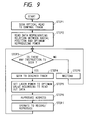
- test zones (b) and (f) are used only in the test of normal recording power. That is, in these zones, while the recording power is varied in several steps, data of a predetermined pattern is recorded at each level of the recording power, and the recorded data are reproduced (the reproducing power is held constant). The recording power by which the highest reproduction signal level is obtained is used as optimum recording power.
- optimum recording power Pwi at certain reproducing power is obtained in inner test zone. Thereafter, a signal recorded at Pwi is reproduced at several levels of reproducing power to obtain reproducing power Pri by which the highest signal level is obtained. An optical head is then moved to outer test zone to obtain optimum reproducing power Pro in the same fashion. As discussed earlier, the linear velocity in the inner zone is different from that in the outer zone. Therefore, the values of Pri and Pro differ from each other due to the difference in the super-resolving effect.
- an optimum reproducing power is obtained from the track number.
- a radial position sensor is attached to an optical head and the radial position is obtained from the sensor output, it is of course possible to obtain the reproducing power from the sensor output, Pri, and Pro.
- general optical discs employ the format called ZCAV having the advantages of a large total capacity and a high speed, in which the data zone (consisting of a plurality of tracks) is divided into several zones (zones O to N) as in Fig. 11.
- each zone data is handled in the same manner as in CAV, and the recording pit length in the innermost zone in each zone is set to correspond to the spot size of a reproducing beam or to the limit which is determined by the super-resolving effect of the disc.
- zones are arranged continuously, therefore, tracks whose boundaries are adjacent to each other have different pit lengths or clock frequencies.
- test recording and reproduction are also performed in several buffer zones between the zones, thereby obtaining an optimum recording power and an optimum reproducing power (see Fig. 12).
- this measurement need not be performed in buffer zones between all of the zones; i.e., only a minimum measurement by which a necessary quality of a reproduction signal can be obtained need be performed. This is so because the rise time upon each insertion of a disc increases if the number of measuring points is unnecessarily increased.
- measuring points are linearly interpolated.
- the relation between the radial position R and the optimum reproducing power Pr is calculated by a polynomial.
- Figs. 8A to 8C show changes in the temperature distribution when the linear velocity is altered.
- the maximum temperature which is reached upon laser irradiation is held constant by changing the reproducing power in accordance with the linear velocity, thereby adjusting the position of Tth in the center of a track.
- the optimum reproducing power does not linearly change because the aperture shape also changes due to the difference in the temperature distribution in a spot which is caused by the linear velocity. Therefore, after the optimum reproducing power is measured in several buffer zones in the same way as in the third Embodiment, the relation between the radial position R and the optimum reproducing power Pr can be calculated by using a polynomial.
- Equation (3) is a polynomial of degree (n-1) and the number of measuring points is n , coefficients a0, a1,..., a n-1 can be uniquely determined.
- the reproducing power at each radial position is calculated in the form of a polynomial of degree (n-1) for the number n of measuring points (see Fig. 13). This further improves the reliability in reproduction.
- the number of measuring points is n
- the relation between the radial position R and the reproducing power Pr is given by a polynomial of degree (n-1).
- approximation can also be used to simplify the relation and improve the measurement accuracy. That is, when the number of measuring points is n , the relation between the radial position R and the reproducing power Pr can be approximated to a polynomial of degree k (n-1 > k) by using a method such as the least squares method or Lagrangian interpolation.
- buffer zones between zones are used to perform test recording and reproduction for obtaining the relation between the radial position R and the reproducing power Pr.
- the buffer zones contain no information such as a track address, it may sometimes be difficult for a recording/reproducing apparatus to perform recording.
- one or more tracks in the innermost zone (or the outermost zone) in one or more zones are used as test tracks, and in power check an optimum reproducing power is obtained in these test tracks (see Fig. 14).
- the tracks provided for the test need only be several tracks in a whole disc. This results in almost no reduction in the capacity of a disc and allows an easy-to-perform recording/reproducing test.
- Fig. 15 is a block diagram for explaining the seventh embodiment of the present invention.
- the same reference numerals as in Fig. 10 denote parts having the same functions, and a detailed description thereof will be omitted.
- a part added to the arrangement in Fig. 10 is a disc detector 12.
- a CPU 1 adjusts focusing control and tracking control and then obtains optimum recording power Pw at certain reproducing power in inner test zone and/or outer test zone shown in Fig. 11. Thereafter, the CPU 1 reproduces a signal, which is recorded with Pw, at several levels of reproducing power, thereby obtaining reproducing power Pr by which the highest signal level is given.
- the CPU 1 also operates an internal or external timer before or after the calculations of Pw and Pr.
- FIG. 15 The eighth embodiment of the present invention will be described in detail below with reference to Fig. 17. Note that the same reference numerals as in Fig. 15 denote parts having the same functions in Fig. 17, and a detailed description thereof will be omitted. A part added to the arrangement in Fig. 15 is a disc temperature detector 13.
- This embodiment is identical with the seventh embodiment in that the optimum reproducing power is obtained by detecting loading of a disc.
- the temperature of a disc just after loading is detected by the disc temperature detector 13 and supplied to a CPU 1 without using a timer.
- this temperature rise can be detected by the disc temperature detector 13. Therefore, information reproduction can be constantly performed under optimum conditions by adjusting the reproducing power for each predetermined temperature rise (see Fig. 18).
- the disc temperature is detected in this embodiment, if the temperature of a disc is difficult to detect, nearly the same effect as discussed above can be obtained by performing an identical operation by detecting the temperature of a disc cartridge.
- the present invention can employ still another method by using the same arrangement as in Fig. 17.
- the ninth embodiment of the present invention is identical with the eighth embodiment in that the reproducing power is adjusted by detecting disc loading and the disc temperature at that time is monitored. In this embodiment, however, the reproducing power when the disc temperature rises is obtained by a calculation. This calculation is based on the assumption that the temperature rise of a disc upon irradiation with a reproducing beam is directly proportional to the intensity of the reproducing beam.
- Fig. 19 is a block diagram for explaining the tenth embodiment of the present invention.
- the same reference numerals as in Fig. 10 denote parts having the same functions, and a detailed description thereof will be omitted.
- Parts added to the arrangement in Fig. 10 are a differentiating circuit 14 and a peak detector 15.
- an output A from a preamplifier 7 is supplied to a reproducing system and at the same time differentiated by the differentiating circuit 14 to yield a differential output B.
- the level of the differential output B is supplied to a CPU 1 via the peak detector 15 and an A/D converter 9.
- Figs. 20A to 20C show changes in the preamplifier output A and the differential output B when an isolated pit recorded in a RAD disc is reproduced while the power is varied in several steps by the CPU 1.
- Fig. 20B shows the preamplifier output A and the differential output B when the reproducing power is set at an optimum value. The leading and trailing edges of the reproduction signal are asymmetrical for the reason explained below.
- the intensity distribution of a reproducing beam on a disc usually takes the form of a Gaussian distribution, and so the reproduction waveform is moderate at both the leading and trailing edges in general discs of no super resolution format.
- the trailing edge is similarly moderate since it can be considered to be identical with that in a general disc.
- an enough quantity of light is obtained on the boundary of the aperture at the leading edge. Therefore, the waveform rises steeply as illustrated in Fig. 20B. Consequently, the differential waveform of that waveform is large on the positive side and small on the negative side.
- the aperture becomes too large as in Fig. 6C. Consequently, the resolving power for a minimum pit decreases, and the amplitude of the preamplifier output A does not increase in proportion to an increase in the quantity of light. Additionally, since the leading edge becomes moderate as the aperture increases in size, the amplitude of the differential signal B decreases.
- the shortest pit is used in adjustment of the reproducing power in order to utilize the reduction in the resolving power with respect to the unnecessary expansion of the aperture.
- the peak level of the differential signal B of the reproduction signal is supplied to the CPU 1 by using the A/D converter 9, and the reproducing power is so adjusted that the level is at a maximum. This allows stable information reproduction independent of the difference between discs or an error in laser power control (see Fig. 21).
- Fig. 22 The 11th embodiment of the present invention will be described in detail below with reference to Fig. 22. Note that the same reference numerals as in Fig. 19 denote parts having the same functions in Fig. 22, and a detailed description thereof will be omitted.
- the arrangement in Fig. 22 differs from the arrangement in Fig. 19 in that a preamplifier output A is directly supplied to an A/D converter 9.
- the accuracy of adjustment can be further improved by determining the optimum reproducing power and readjusting the recording power in accordance with the optimum reproducing power determined.
Landscapes
- Optical Recording Or Reproduction (AREA)
- Optical Head (AREA)
Applications Claiming Priority (9)
| Application Number | Priority Date | Filing Date | Title |
|---|---|---|---|
| JP28785293 | 1993-11-17 | ||
| JP287852/93 | 1993-11-17 | ||
| JP28785193 | 1993-11-17 | ||
| JP287851/93 | 1993-11-17 | ||
| JP28785393 | 1993-11-17 | ||
| JP28785393A JP3249000B2 (ja) | 1993-11-17 | 1993-11-17 | 光学的情報記録再生装置 |
| JP287853/93 | 1993-11-17 | ||
| JP28785193 | 1993-11-17 | ||
| JP28785293 | 1993-11-17 |
Publications (3)
| Publication Number | Publication Date |
|---|---|
| EP0653749A2 true EP0653749A2 (de) | 1995-05-17 |
| EP0653749A3 EP0653749A3 (de) | 1995-11-15 |
| EP0653749B1 EP0653749B1 (de) | 2001-09-05 |
Family
ID=27337387
Family Applications (1)
| Application Number | Title | Priority Date | Filing Date |
|---|---|---|---|
| EP94308432A Expired - Lifetime EP0653749B1 (de) | 1993-11-17 | 1994-11-15 | Optisches Informationsaufzeichnungs-/wiedergabegerät und -verfahren mit einer Funktion zur Einstellung der Wiedergabeleistung |
Country Status (7)
| Country | Link |
|---|---|
| US (1) | US5703841A (de) |
| EP (1) | EP0653749B1 (de) |
| KR (1) | KR100283632B1 (de) |
| AU (1) | AU684560B2 (de) |
| CA (1) | CA2135986C (de) |
| DE (1) | DE69428178T2 (de) |
| ES (1) | ES2161240T3 (de) |
Cited By (3)
| Publication number | Priority date | Publication date | Assignee | Title |
|---|---|---|---|---|
| EP0833312A1 (de) * | 1996-09-30 | 1998-04-01 | Nikon Corporation | Vorrichtung und Verfahren zur Wiedergabe von Informationen |
| EP0907168A3 (de) * | 1997-10-01 | 2000-03-22 | Canon Kabushiki Kaisha | Magneto-optisches Aufzeichnungs-/ Wiedergabeverfahren und -gerät |
| EP0896326A3 (de) * | 1997-08-04 | 2001-01-24 | Sharp Kabushiki Kaisha | Verfahren und Vorrichtung zur Steuerung der Wiedergabelichtmenge für eine optische Speichervorrichtung und optisches Aufzeichnungsmedium |
Families Citing this family (23)
| Publication number | Priority date | Publication date | Assignee | Title |
|---|---|---|---|---|
| JP3333613B2 (ja) * | 1993-12-07 | 2002-10-15 | 株式会社日立製作所 | 光情報記録媒体並びに光情報記録再生方法及び光情報記録再生装置 |
| US6111841A (en) * | 1996-01-10 | 2000-08-29 | Nikon Corporation | Apparatus for and method of controlling playback light intensity for an optical recording medium |
| US6052347A (en) * | 1996-02-23 | 2000-04-18 | Ricoh Company, Ltd. | Method and apparatus for detecting optimum recording power for an optical disk |
| JP3424037B2 (ja) * | 1996-04-05 | 2003-07-07 | 富士通株式会社 | 光磁気記録媒体の情報再生方法及び情報記録方法、並びに光磁気再生装置 |
| JPH10149595A (ja) * | 1996-09-18 | 1998-06-02 | Canon Inc | 磁壁を移動させて情報の再生を行う情報再生装置 |
| US7123563B2 (en) * | 1996-12-06 | 2006-10-17 | Koninklijke Philips Electronics N.V. | Optical recording method and apparatus using this method |
| RU2214629C2 (ru) * | 1996-12-24 | 2003-10-20 | Конинклейке Филипс Электроникс Н.В. | Способ оптической записи и устройство, использующее этот способ |
| JP4272279B2 (ja) | 1998-09-28 | 2009-06-03 | パナソニック株式会社 | 光学的情報記録装置、光学的情報記録媒体および光学的情報記録方法 |
| JP3654069B2 (ja) * | 1998-10-27 | 2005-06-02 | 富士通株式会社 | 光学的記憶媒体及びその処理方法と光学的記憶媒体処理装置 |
| JP2000331397A (ja) * | 1999-05-19 | 2000-11-30 | Sony Corp | 光出力調整装置及び光出力調整方法 |
| WO2002075622A2 (en) * | 2001-03-20 | 2002-09-26 | Abraham Blau | System and method for item exchange |
| US6845071B2 (en) * | 2001-03-28 | 2005-01-18 | Matsushita Electric Industrial Co., Ltd. | Optical disc apparatus and recording power determining method thereof |
| JP2002334439A (ja) * | 2001-05-01 | 2002-11-22 | Eigun Kigyo Kofun Yugenkoshi | ディスクドライブのレーザーエネルギー量の補償方法 |
| EP1490865A2 (de) * | 2001-09-12 | 2004-12-29 | Koninklijke Philips Electronics N.V. | Strahlungsenergiesteuerung und/oder feldsteuerung für ein aufzeichnungsmedium mit domäneerweiterung |
| TWI270875B (en) | 2002-01-11 | 2007-01-11 | Via Tech Inc | A method for determining a writing power of a compact disc drive |
| US6853610B2 (en) * | 2002-02-13 | 2005-02-08 | Benq Corporation | Determination of recording power of radiation beam for recording information onto recording medium |
| JP3787316B2 (ja) * | 2002-04-26 | 2006-06-21 | キヤノン株式会社 | 光磁気記録再生装置 |
| JP3974447B2 (ja) * | 2002-05-08 | 2007-09-12 | アルパイン株式会社 | 光ディスク再生装置及び光ディスク再生装置の自動調整方法 |
| WO2005064599A1 (ja) * | 2003-12-26 | 2005-07-14 | Matsushita Electric Industrial Co., Ltd. | 情報記録媒体及び情報記録再生装置 |
| TWI241571B (en) * | 2004-05-25 | 2005-10-11 | Mediatek Inc | Multi-directional controlling method of optical disk drive laser power and device using same |
| US7729219B2 (en) * | 2005-10-07 | 2010-06-01 | Mediatek Inc. | Read and write power control methods and system for optical recording device |
| KR101244908B1 (ko) * | 2005-12-20 | 2013-03-18 | 티디케이가부시기가이샤 | 광기록 매체에 대한 최적 재생 파워를 결정하는 방법 및 장치 |
| CN107741228A (zh) * | 2017-05-24 | 2018-02-27 | 北京大学 | 一种基于重心拉格朗日插值法的捷联惯导姿态解算方法 |
Family Cites Families (8)
| Publication number | Priority date | Publication date | Assignee | Title |
|---|---|---|---|---|
| JPH01201829A (ja) * | 1988-02-05 | 1989-08-14 | Canon Inc | 光学的情報記録再生装置 |
| JPH0316038A (ja) * | 1989-06-13 | 1991-01-24 | Teac Corp | 情報記録再生装置 |
| JP2682222B2 (ja) * | 1990-10-01 | 1997-11-26 | 三菱電機株式会社 | 情報記憶装置 |
| EP0526641B1 (de) * | 1991-02-05 | 1996-05-08 | Sony Corporation | Verfahren zur Wiedergabe eines Signals aus einem optischen Aufzeichnungsmedium |
| US5390162A (en) * | 1991-02-05 | 1995-02-14 | Sony Corporation | Method for reproducing signals recorded on optical recording medium |
| JP2959586B2 (ja) * | 1991-02-12 | 1999-10-06 | ソニー株式会社 | 光磁気ディスクの再生方法 |
| EP0524315B1 (de) * | 1991-02-13 | 1996-07-03 | Sony Corporation | Verfahren zur wiedergabe von signalen in optischem aufzeichnungsmedium |
| JP2795567B2 (ja) * | 1991-11-25 | 1998-09-10 | シャープ株式会社 | 光磁気ディスク及び再生方法 |
-
1994
- 1994-11-15 ES ES94308432T patent/ES2161240T3/es not_active Expired - Lifetime
- 1994-11-15 EP EP94308432A patent/EP0653749B1/de not_active Expired - Lifetime
- 1994-11-15 DE DE69428178T patent/DE69428178T2/de not_active Expired - Fee Related
- 1994-11-16 CA CA002135986A patent/CA2135986C/en not_active Expired - Fee Related
- 1994-11-16 KR KR1019940030011A patent/KR100283632B1/ko not_active Expired - Fee Related
- 1994-11-16 AU AU78864/94A patent/AU684560B2/en not_active Ceased
-
1997
- 1997-01-09 US US08/781,141 patent/US5703841A/en not_active Expired - Lifetime
Cited By (5)
| Publication number | Priority date | Publication date | Assignee | Title |
|---|---|---|---|---|
| EP0833312A1 (de) * | 1996-09-30 | 1998-04-01 | Nikon Corporation | Vorrichtung und Verfahren zur Wiedergabe von Informationen |
| EP0896326A3 (de) * | 1997-08-04 | 2001-01-24 | Sharp Kabushiki Kaisha | Verfahren und Vorrichtung zur Steuerung der Wiedergabelichtmenge für eine optische Speichervorrichtung und optisches Aufzeichnungsmedium |
| US6392970B1 (en) | 1997-08-04 | 2002-05-21 | Sharp Kabushiki Kaisha | Reproducing light quantity control method for optical memory device, and reproducing light quantity control device, and optical recording medium |
| EP0907168A3 (de) * | 1997-10-01 | 2000-03-22 | Canon Kabushiki Kaisha | Magneto-optisches Aufzeichnungs-/ Wiedergabeverfahren und -gerät |
| US6246641B1 (en) | 1997-10-01 | 2001-06-12 | Canon Kabushiki Kaisha | Magneto-optical recording-reproducing method and apparatus utilizing domain wall displacement |
Also Published As
| Publication number | Publication date |
|---|---|
| CA2135986A1 (en) | 1995-05-18 |
| US5703841A (en) | 1997-12-30 |
| ES2161240T3 (es) | 2001-12-01 |
| CA2135986C (en) | 1999-05-04 |
| KR950015232A (ko) | 1995-06-16 |
| DE69428178D1 (de) | 2001-10-11 |
| AU684560B2 (en) | 1997-12-18 |
| KR100283632B1 (ko) | 2001-03-02 |
| DE69428178T2 (de) | 2002-07-04 |
| EP0653749A3 (de) | 1995-11-15 |
| EP0653749B1 (de) | 2001-09-05 |
| AU7886494A (en) | 1995-05-25 |
Similar Documents
| Publication | Publication Date | Title |
|---|---|---|
| EP0653749B1 (de) | Optisches Informationsaufzeichnungs-/wiedergabegerät und -verfahren mit einer Funktion zur Einstellung der Wiedergabeleistung | |
| US7095705B2 (en) | Optical information recording medium and optical information recording and reproducing apparatus | |
| JPH056590A (ja) | 光磁気記録装置 | |
| US5463600A (en) | Magneto-optical recording system using recording waveform having a plurality of power levels providing high recording density | |
| EP0488648B1 (de) | Gerät zur Aufzeichnung/Wiedergabe von optischen Informationen | |
| EP0569054B1 (de) | Magneto-optisches Aufzeichnungsgerät | |
| US6246641B1 (en) | Magneto-optical recording-reproducing method and apparatus utilizing domain wall displacement | |
| JP3787316B2 (ja) | 光磁気記録再生装置 | |
| EP0327315B1 (de) | Magneto-optisches Aufzeichnungsmedium und Verfahren um auf dieses Medium aufzuzeichnen | |
| JP3762813B2 (ja) | 光記録媒体の最適記録及び再生光量の決定方法並びに記録再生方法及び装置 | |
| US20050088954A1 (en) | Optical recording medium and optical storage device | |
| JPH0729238A (ja) | 光記録の再生方法 | |
| JP2778428B2 (ja) | 光ディスク装置 | |
| JP3249000B2 (ja) | 光学的情報記録再生装置 | |
| JPH07192338A (ja) | 光学的情報記録再生装置 | |
| Sumi et al. | Advanced storage magnetooptical disk (AS-MO) system | |
| JPH1139803A (ja) | 光記録媒体、光記録方法および光記録装置 | |
| JPH01191330A (ja) | 光学的情報処理装置 | |
| JP2872801B2 (ja) | 光磁気記録再生装置 | |
| JPH11120566A (ja) | 記録再生装置の立ち上げ方法及び記録再生装置 | |
| JPH07192337A (ja) | 光学的情報記録再生装置 | |
| JPH10283688A (ja) | 光記録方法および光記録装置 | |
| JP2003317340A (ja) | 光磁気ディスク装置および磁壁移動型光磁気記録媒体 | |
| JPH11144249A (ja) | 光記録方法および光記録再生装置 | |
| JP2002251729A (ja) | 光ディスク記録装置およびその調整方法 |
Legal Events
| Date | Code | Title | Description |
|---|---|---|---|
| PUAI | Public reference made under article 153(3) epc to a published international application that has entered the european phase |
Free format text: ORIGINAL CODE: 0009012 |
|
| AK | Designated contracting states |
Kind code of ref document: A2 Designated state(s): DE ES FR GB IT NL |
|
| PUAL | Search report despatched |
Free format text: ORIGINAL CODE: 0009013 |
|
| AK | Designated contracting states |
Kind code of ref document: A3 Designated state(s): DE ES FR GB IT NL |
|
| 17P | Request for examination filed |
Effective date: 19960328 |
|
| 17Q | First examination report despatched |
Effective date: 19980804 |
|
| GRAG | Despatch of communication of intention to grant |
Free format text: ORIGINAL CODE: EPIDOS AGRA |
|
| GRAG | Despatch of communication of intention to grant |
Free format text: ORIGINAL CODE: EPIDOS AGRA |
|
| GRAG | Despatch of communication of intention to grant |
Free format text: ORIGINAL CODE: EPIDOS AGRA |
|
| GRAH | Despatch of communication of intention to grant a patent |
Free format text: ORIGINAL CODE: EPIDOS IGRA |
|
| GRAH | Despatch of communication of intention to grant a patent |
Free format text: ORIGINAL CODE: EPIDOS IGRA |
|
| GRAA | (expected) grant |
Free format text: ORIGINAL CODE: 0009210 |
|
| AK | Designated contracting states |
Kind code of ref document: B1 Designated state(s): DE ES FR GB IT NL |
|
| REF | Corresponds to: |
Ref document number: 69428178 Country of ref document: DE Date of ref document: 20011011 |
|
| REG | Reference to a national code |
Ref country code: ES Ref legal event code: FG2A Ref document number: 2161240 Country of ref document: ES Kind code of ref document: T3 |
|
| REG | Reference to a national code |
Ref country code: GB Ref legal event code: IF02 |
|
| ET | Fr: translation filed | ||
| PLBE | No opposition filed within time limit |
Free format text: ORIGINAL CODE: 0009261 |
|
| STAA | Information on the status of an ep patent application or granted ep patent |
Free format text: STATUS: NO OPPOSITION FILED WITHIN TIME LIMIT |
|
| 26N | No opposition filed | ||
| PGFP | Annual fee paid to national office [announced via postgrant information from national office to epo] |
Ref country code: GB Payment date: 20041101 Year of fee payment: 11 |
|
| PGFP | Annual fee paid to national office [announced via postgrant information from national office to epo] |
Ref country code: ES Payment date: 20041105 Year of fee payment: 11 |
|
| PGFP | Annual fee paid to national office [announced via postgrant information from national office to epo] |
Ref country code: NL Payment date: 20041112 Year of fee payment: 11 |
|
| PGFP | Annual fee paid to national office [announced via postgrant information from national office to epo] |
Ref country code: FR Payment date: 20041126 Year of fee payment: 11 |
|
| PGFP | Annual fee paid to national office [announced via postgrant information from national office to epo] |
Ref country code: DE Payment date: 20050121 Year of fee payment: 11 |
|
| PG25 | Lapsed in a contracting state [announced via postgrant information from national office to epo] |
Ref country code: IT Free format text: LAPSE BECAUSE OF NON-PAYMENT OF DUE FEES Effective date: 20051115 Ref country code: GB Free format text: LAPSE BECAUSE OF NON-PAYMENT OF DUE FEES Effective date: 20051115 |
|
| PG25 | Lapsed in a contracting state [announced via postgrant information from national office to epo] |
Ref country code: ES Free format text: LAPSE BECAUSE OF NON-PAYMENT OF DUE FEES Effective date: 20051116 |
|
| PG25 | Lapsed in a contracting state [announced via postgrant information from national office to epo] |
Ref country code: NL Free format text: LAPSE BECAUSE OF NON-PAYMENT OF DUE FEES Effective date: 20060601 Ref country code: DE Free format text: LAPSE BECAUSE OF NON-PAYMENT OF DUE FEES Effective date: 20060601 |
|
| GBPC | Gb: european patent ceased through non-payment of renewal fee |
Effective date: 20051115 |
|
| PG25 | Lapsed in a contracting state [announced via postgrant information from national office to epo] |
Ref country code: FR Free format text: LAPSE BECAUSE OF NON-PAYMENT OF DUE FEES Effective date: 20060731 |
|
| NLV4 | Nl: lapsed or anulled due to non-payment of the annual fee |
Effective date: 20060601 |
|
| REG | Reference to a national code |
Ref country code: FR Ref legal event code: ST Effective date: 20060731 |
|
| REG | Reference to a national code |
Ref country code: ES Ref legal event code: FD2A Effective date: 20051116 |