EP0653845A1 - Verfahren zum Synchronisieren eines Referenzoszillators mit einem Hauptoszillator - Google Patents
Verfahren zum Synchronisieren eines Referenzoszillators mit einem Hauptoszillator Download PDFInfo
- Publication number
- EP0653845A1 EP0653845A1 EP94307270A EP94307270A EP0653845A1 EP 0653845 A1 EP0653845 A1 EP 0653845A1 EP 94307270 A EP94307270 A EP 94307270A EP 94307270 A EP94307270 A EP 94307270A EP 0653845 A1 EP0653845 A1 EP 0653845A1
- Authority
- EP
- European Patent Office
- Prior art keywords
- microcell
- base
- time
- signal
- oscillator
- Prior art date
- Legal status (The legal status is an assumption and is not a legal conclusion. Google has not performed a legal analysis and makes no representation as to the accuracy of the status listed.)
- Granted
Links
- 238000000034 method Methods 0.000 title claims abstract description 17
- 238000012937 correction Methods 0.000 claims abstract description 12
- 230000005540 biological transmission Effects 0.000 claims description 18
- 230000008859 change Effects 0.000 claims description 4
- 239000013078 crystal Substances 0.000 claims description 4
- 238000002592 echocardiography Methods 0.000 claims description 3
- 229910052701 rubidium Inorganic materials 0.000 claims description 2
- IGLNJRXAVVLDKE-UHFFFAOYSA-N rubidium atom Chemical compound [Rb] IGLNJRXAVVLDKE-UHFFFAOYSA-N 0.000 claims description 2
- 239000002609 medium Substances 0.000 description 5
- 238000005516 engineering process Methods 0.000 description 3
- 230000001360 synchronised effect Effects 0.000 description 3
- 239000000969 carrier Substances 0.000 description 2
- 239000000835 fiber Substances 0.000 description 2
- 238000012423 maintenance Methods 0.000 description 2
- 238000005259 measurement Methods 0.000 description 2
- 238000004891 communication Methods 0.000 description 1
- 238000011161 development Methods 0.000 description 1
- 238000010586 diagram Methods 0.000 description 1
- 230000006870 function Effects 0.000 description 1
- 239000003550 marker Substances 0.000 description 1
- 238000012986 modification Methods 0.000 description 1
- 230000004048 modification Effects 0.000 description 1
- 230000008450 motivation Effects 0.000 description 1
- 239000013307 optical fiber Substances 0.000 description 1
- 230000008520 organization Effects 0.000 description 1
- 238000011160 research Methods 0.000 description 1
- 238000012360 testing method Methods 0.000 description 1
- 239000006163 transport media Substances 0.000 description 1
Images

Classifications
-
- H—ELECTRICITY
- H04—ELECTRIC COMMUNICATION TECHNIQUE
- H04B—TRANSMISSION
- H04B1/00—Details of transmission systems, not covered by a single one of groups H04B3/00 - H04B13/00; Details of transmission systems not characterised by the medium used for transmission
- H04B1/02—Transmitters
-
- H—ELECTRICITY
- H03—ELECTRONIC CIRCUITRY
- H03L—AUTOMATIC CONTROL, STARTING, SYNCHRONISATION OR STABILISATION OF GENERATORS OF ELECTRONIC OSCILLATIONS OR PULSES
- H03L7/00—Automatic control of frequency or phase; Synchronisation
-
- G—PHYSICS
- G04—HOROLOGY
- G04G—ELECTRONIC TIME-PIECES
- G04G7/00—Synchronisation
-
- H—ELECTRICITY
- H04—ELECTRIC COMMUNICATION TECHNIQUE
- H04J—MULTIPLEX COMMUNICATION
- H04J3/00—Time-division multiplex systems
- H04J3/02—Details
- H04J3/06—Synchronising arrangements
- H04J3/0635—Clock or time synchronisation in a network
- H04J3/0638—Clock or time synchronisation among nodes; Internode synchronisation
Definitions
- the present invention relates generally to a device and the method to synchronize timers. More specifically, the invention relates to the device and the method to synchronize a master oscillator located at a base station and a slave oscillator located at a microcell. Such synchronization facilitates simulcasting of radio frequency channels.
- the article cites the principle limitation of time dissemination as being the uncertainty in the velocity of the propagation of the information through the medium separating the transmitter and the receiver.
- the delay typically in the order of milliseconds, depends upon the physical length of the path and on the group velocity of the signal. Generally, neither of these parameters is known. Consequently, to achieve the highest degree of synchronization, real time measurements of the transit time must be taken.
- the delay can be determined by measuring the time duration between transmitting a pulse to the user and receiving an echoed pulse. Half of this round trip delay is the time required for the signal to reach the user assuming that the communication medium is reciprocal.
- the NIST has developed a simple telephone system for the automated setting of clocks in digital systems.
- NIST has developed software to facilitate automatic dialing, selecting a time zone, selecting a mode of operation, echoing the on-time marker (OTM), setting of the computer clock, archiving of clock offset, and transmitting a signal to the parallel port of a computer, which can be used to produce an external time pulse coincident with the OTM.
- OTM on-time marker
- the article provides diagrams of simple circuits to convert-the signal sent to the printer port to a positive pulse.
- the article also details a circuit that echoes all characters from the user and provides an external pulse when the OTM is received. This circuit requires a modem but does not require a computer.
- the article basically focuses on the application of ACTS for the maintenance of accurate time within a digital computer.
- the article suggests tagging business transactions or scientific data with the exact time. Such tagging becomes particularly useful where a multiplicity of computers independently tag events, and thus require a common time standard.
- the article mentions a second application aimed at the measurement of frequency.
- the pulses coincident with the OTM are used to start and stop a counter.
- the counter counts the output of the oscillator under the test. By comparing the pulses to the counts, an oscillator can be calibrated using exact time.
- the system can be used to set digital clocks, or to perform frequency calibrations at an accuracy of one part in 108 for a one day period.
- the article also speculates on the future development of the system and the new products which it might spawn. It suggests a digital clock comprising a microprocessor incorporated into a phone receiver. To maintain exact time according to the National Institute of Standards and Technology, the clock would access the ACTS via the telephone. Such a phone could be networked to other phones in a school or factory to provide the exact time throughout the organization. Additionally, the article suggests automatic calling to enable the user to call during less expensive non-peak hours.
- the article limits the application of the method of synchronization to time -- both in the maintenance of accurate clocks and the calibration of frequency oscillators.
- the prior art lacks motivation to use the synchronization method in telecommunications. More specifically, the article does not suggest that the ACTS could be modified to enable a base station and a microcell to simulcast.
- the present invention is directed at enabling a base station and a microcell to simulcast.
- the present invention is aimed at synchronizing the oscillators located at the base station and the microcell when the two stations are joined by a metallic medium.
- One object of the invention is to provide a configuration of circuitry which synchronizes the oscillator of the base station with the oscillator of the microcell. By synchronizing the oscillators, the RF carriers synthesized at both the base station and the microcell will have the same frequency, thus facilitating simulcasting.
- Another object of the invention is to compensate for the transmission delay before the base station transmits a time-of-day signal. Such compensation would not only facilitate simulcasting by providing the microcell with a real time reference, but also provide an absolute time standard for other functions at the microcell.
- Yet another object of the invention is to provide a method for synchronizing the oscillators by maintaining a constant time delay between the transmission of the base station time-of-day signal and the microcell time-of-day signal. By maintaining a constant delay, the transmission delay between the base station and the microcell is negated, and the oscillators remain synchronized. Thus, simulcasting is facilitated.
- Still another object of the present invention is a method to adjust the base station's time-of-day signal to compensate for the time delay before it is transmitted to the microcell. In this way, a real time reference is available to the microcell which enables it to simulcast.
- the present invention teaches the circuitry required, as well as the method, to enable simulcasting of a base station and a microcell linked together by a metallic medium.
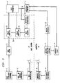
- Fig. 1 depicts a preferred embodiment of the present invention.
- Fig. 2 shows another preferred embodiment which employs a compensation circuit.
- RF radio frequencies
- T1 The problem with T1, however, is that due to its limited band width, a RF signal cannot be transported unmodified from the base station to the microcell. Instead, the RF signal -- a voice or data transmission --is modulated into an RF carrier generated at the microcell site.
- the RF carriers are synthesized using a reference frequency generated by an oscillator.
- a high stability oscillator As is used at the base station; rather, a less expensive crystal reference oscillator is used.
- Some means is therefore needed to synchronize a crystal reference oscillator at the microcell site with the master oscillator at the base station. The present invention provides these means.
- Fig. 1 the schematic shows the present invention which enables a base broadcaster 3 and a microcell broadcaster 16 to "simulcast.” Simulcasting, or broadcasting at the same frequency, requires synchronization of a base oscillator 1 located at a base station 31 and a microcell oscillator 12 located at a microcell 30.
- Base oscillator 1 which is typically a high stability oscillator such as rubidium -- provides a reference to a base RF carrier synthesizer 17, and a base clock 2 which outputs a base time-of-day signal.
- Microcell oscillator 12 is a crystal oscillator which can be adjusted by a digital controller 13 containing a microprocessor. The output of microcell oscillator 12 is used as a reference frequency for both a microcell RF carrier synthesizer 15, and a microcell clock 14 which outputs a microcell time-of-day signal.
- Base clock 2 periodically sends the base time-of-day signal to a base transmitter 4 which transmits it over metallic link 5 to microcell 30.
- the base time-of-day signal is compared with the microcell time-of-day signal in a microcell comparer 11.
- Microcell comparer 11 periodically monitors the signals and calculates the time difference between the two signals. This time difference represents the accumulated error between base clock 2 and microcell clock 14 plus the transmission delay between base transmitter 4 and comparer 11. Since metallic link 5 imputes a constant transmission delay, the time difference should remain constant if base oscillator 1 and microcell oscillator 12 are synchronized. If, however, the time difference changes, the oscillators are not synchronized.
- microcell comparer 11 sends a correction signal to digital controller 13 corresponding to the time difference change.
- Digital controller 13 adjusts microcell oscillator 12 to bring the microcell time-of-day signal back within the constant transmission delay of metallic link 5.
- the frequency of microcell oscillator 12 can be brought arbitrarily close to the frequency of base oscillator 3.
- Digital controller 13 not only adjusts microcell oscillator 12, but also resets microcell clock 14. Resetting microcell clock 14 may be required in the event of a power failure, or simply to match microcell clock 14 with base clock 2.
- Fig. 2 depicts another preferred embodiment of the present invention.
- This particular embodiment comprises an automatic compensator circuit 33.
- the time-of-day signal is sent over metallic link 5, there is a transmission delay before this signal reaches the microcell. This transmission delay is unpredictable due to uncertainties in the configuration of metallic link 5.
- the embodiment of Fig. 2, however, can overcome this problem.
- a base transmitter 4 sends a pulse both to a delay processor 8, and along a metallic link 5 to a microcell transponder 6.
- Microcell transponder 6 echoes the pulse back to a base receiver 7, and base receiver sends a return signal to delay processor 8.
- Delay processor 8 measures the time duration between receiving the pulse from base transmitter 4 and receiving the return signal from base receiver 7. Delay processor 8 then divides this time duration in half to arrive at the transmission delay. This calculation represents the time required for a signal sent from base station 31 to reach microcell 30. To compensate for the transmission delay, delay processor 8 sends a delay signal to a delay adjuster 9 which advances the base time-of-day signal before base transmitter 4 transmits it to microcell comparer 11.
Landscapes
- Engineering & Computer Science (AREA)
- Computer Networks & Wireless Communication (AREA)
- Signal Processing (AREA)
- Physics & Mathematics (AREA)
- General Physics & Mathematics (AREA)
- Synchronisation In Digital Transmission Systems (AREA)
- Mobile Radio Communication Systems (AREA)
- Transmitters (AREA)
- Electric Clocks (AREA)
Applications Claiming Priority (2)
| Application Number | Priority Date | Filing Date | Title |
|---|---|---|---|
| US138583 | 1993-10-15 | ||
| US08/138,583 US5469467A (en) | 1993-10-15 | 1993-10-15 | Method for synchronizing the reference frequency oscillator of a metallic-based microcell to a master oscillator |
Publications (2)
| Publication Number | Publication Date |
|---|---|
| EP0653845A1 true EP0653845A1 (de) | 1995-05-17 |
| EP0653845B1 EP0653845B1 (de) | 2000-06-07 |
Family
ID=22482670
Family Applications (1)
| Application Number | Title | Priority Date | Filing Date |
|---|---|---|---|
| EP94307270A Expired - Lifetime EP0653845B1 (de) | 1993-10-15 | 1994-10-05 | Verfahren und Vorrichtung zur Synchronisierung der Sendefrequenz zweier Basisstationen |
Country Status (6)
| Country | Link |
|---|---|
| US (1) | US5469467A (de) |
| EP (1) | EP0653845B1 (de) |
| JP (1) | JP2665167B2 (de) |
| KR (1) | KR970007980B1 (de) |
| DE (1) | DE69424844T2 (de) |
| SG (1) | SG54111A1 (de) |
Cited By (2)
| Publication number | Priority date | Publication date | Assignee | Title |
|---|---|---|---|---|
| WO2007115626A1 (de) * | 2006-04-03 | 2007-10-18 | Rohde & Schwarz Gmbh & Co. Kg | Synchronisieranordnung für die hochfrequenz-sender eines gleichwellen-netzes |
| EP1845740A4 (de) * | 2005-02-01 | 2011-06-22 | Mitsubishi Electric Corp | System zur synchronisation zwischen basisstationen, synchronisations-steuereinrichtung und basisstation |
Families Citing this family (12)
| Publication number | Priority date | Publication date | Assignee | Title |
|---|---|---|---|---|
| US5659545A (en) * | 1994-11-15 | 1997-08-19 | Motorola, Inc. | Apparatus for mobile unit acquisition in a satellite communication system and method therefor |
| DE19523489A1 (de) * | 1995-06-28 | 1997-01-02 | Sel Alcatel Ag | Verfahren und Schaltungsanordnung zur Synchronisation von Impulsrahmen in multizellularen Telekommunikationsanlagen |
| US5953384A (en) * | 1997-06-05 | 1999-09-14 | Motorola, Inc. | Automatic measurement of GPS cable delay time |
| JP2000050351A (ja) * | 1998-07-27 | 2000-02-18 | Nec Corp | 移動体通信装置および移動体通信における同期確立方法 |
| WO2002035734A1 (en) * | 2000-10-26 | 2002-05-02 | Sk Telecom Co., Ltd. | Apparatus and method for acquiring synchronization |
| US7324857B2 (en) * | 2002-04-19 | 2008-01-29 | Gateway Inc. | Method to synchronize playback of multicast audio streams on a local network |
| US7392102B2 (en) * | 2002-04-23 | 2008-06-24 | Gateway Inc. | Method of synchronizing the playback of a digital audio broadcast using an audio waveform sample |
| US7209795B2 (en) | 2002-04-23 | 2007-04-24 | Gateway Inc. | Method of synchronizing the playback of a digital audio broadcast by inserting a control track pulse |
| US7333519B2 (en) * | 2002-04-23 | 2008-02-19 | Gateway Inc. | Method of manually fine tuning audio synchronization of a home network |
| US8014378B1 (en) | 2003-10-23 | 2011-09-06 | Itt Manufacturing Enterprise, Inc. | Method and apparatus for automatic control of time-of-day synchronization and merging of networks |
| US7343255B2 (en) * | 2004-07-07 | 2008-03-11 | Itron, Inc. | Dual source real time clock synchronization system and method |
| US7961554B2 (en) * | 2008-01-11 | 2011-06-14 | Cellnet Innovations, Inc. | Methods and systems for accurate time-keeping on metering and other network communication devices |
Citations (5)
| Publication number | Priority date | Publication date | Assignee | Title |
|---|---|---|---|---|
| GB2000651A (en) * | 1977-06-30 | 1979-01-10 | Int Standard Electric Corp | Master clock arrangement |
| DE2829651A1 (de) * | 1978-07-06 | 1980-01-24 | Hubert Dipl Ing Dr Effenberger | Stell-, synchronisier- und reguliervorrichtung insbesondere fuer elektronisch gesteuerte uhren |
| DE3042808A1 (de) * | 1980-11-13 | 1982-06-09 | Brown, Boveri & Cie Ag, 6800 Mannheim | Regeleinrichtung zur gleichlaufsteuerung von rechneruhren mit einer hauptuhr bei einem dezentralen mehrrechnersystem |
| GB2100890A (en) * | 1981-07-01 | 1983-01-06 | Chu Tsan Chen | Automatic correction of electronic timepiece |
| JPS60214291A (ja) * | 1984-04-11 | 1985-10-26 | Nec Corp | 時計管理方式 |
Family Cites Families (8)
| Publication number | Priority date | Publication date | Assignee | Title |
|---|---|---|---|---|
| JPS5972124A (ja) * | 1982-10-18 | 1984-04-24 | 松下電器産業株式会社 | フイルムコンデンサ− |
| US4696052A (en) * | 1985-12-31 | 1987-09-22 | Motorola Inc. | Simulcast transmitter apparatus having automatic synchronization capability |
| JPS62214739A (ja) * | 1986-03-15 | 1987-09-21 | Nec Corp | 同期制御方式 |
| US5059926A (en) * | 1991-03-13 | 1991-10-22 | Motorola, Inc. | Frequency synchronization apparatus |
| US5257404A (en) * | 1991-10-04 | 1993-10-26 | Motorola, Inc. | Simulcast synchronization and equalization system and method therefor |
| US5261118A (en) * | 1991-10-04 | 1993-11-09 | Motorola, Inc. | Simulcast synchronization and equalization system and method therefor |
| US5280629A (en) * | 1991-12-06 | 1994-01-18 | Motorola, Inc. | Technique for measuring channel delay |
| US5363376A (en) * | 1993-07-30 | 1994-11-08 | Bell Communications Research, Inc. | Method and apparatus for synchronizing timing among radio ports in wireless communications systems |
-
1993
- 1993-10-15 US US08/138,583 patent/US5469467A/en not_active Expired - Lifetime
-
1994
- 1994-10-05 SG SG1996000602A patent/SG54111A1/en unknown
- 1994-10-05 DE DE69424844T patent/DE69424844T2/de not_active Expired - Fee Related
- 1994-10-05 EP EP94307270A patent/EP0653845B1/de not_active Expired - Lifetime
- 1994-10-12 KR KR1019940026038A patent/KR970007980B1/ko not_active Expired - Fee Related
- 1994-10-14 JP JP6274274A patent/JP2665167B2/ja not_active Expired - Fee Related
Patent Citations (5)
| Publication number | Priority date | Publication date | Assignee | Title |
|---|---|---|---|---|
| GB2000651A (en) * | 1977-06-30 | 1979-01-10 | Int Standard Electric Corp | Master clock arrangement |
| DE2829651A1 (de) * | 1978-07-06 | 1980-01-24 | Hubert Dipl Ing Dr Effenberger | Stell-, synchronisier- und reguliervorrichtung insbesondere fuer elektronisch gesteuerte uhren |
| DE3042808A1 (de) * | 1980-11-13 | 1982-06-09 | Brown, Boveri & Cie Ag, 6800 Mannheim | Regeleinrichtung zur gleichlaufsteuerung von rechneruhren mit einer hauptuhr bei einem dezentralen mehrrechnersystem |
| GB2100890A (en) * | 1981-07-01 | 1983-01-06 | Chu Tsan Chen | Automatic correction of electronic timepiece |
| JPS60214291A (ja) * | 1984-04-11 | 1985-10-26 | Nec Corp | 時計管理方式 |
Non-Patent Citations (2)
| Title |
|---|
| PATENT ABSTRACTS OF JAPAN vol. 10, no. 76 (P - 440)<2133> 26 March 1986 (1986-03-26) * |
| W. GROVER ET. AL.: "Precision Time Transfer in Transport Networks using Digital Crossconnect Systems", IEEE GLOBAL TELECOMMUNICATIONS CONFERENCE AND EXHIBITION, vol. 3, 1 December 1988 (1988-12-01), HOLLYWOOD,FLORIDA, pages 1544 - 1548 * |
Cited By (3)
| Publication number | Priority date | Publication date | Assignee | Title |
|---|---|---|---|---|
| EP1845740A4 (de) * | 2005-02-01 | 2011-06-22 | Mitsubishi Electric Corp | System zur synchronisation zwischen basisstationen, synchronisations-steuereinrichtung und basisstation |
| WO2007115626A1 (de) * | 2006-04-03 | 2007-10-18 | Rohde & Schwarz Gmbh & Co. Kg | Synchronisieranordnung für die hochfrequenz-sender eines gleichwellen-netzes |
| US8605848B2 (en) | 2006-04-03 | 2013-12-10 | Rohde & Schwarz Gmbh & Co. Kg | Arrangement for synchronizing high-frequency transmitters of a common-wave network |
Also Published As
| Publication number | Publication date |
|---|---|
| SG54111A1 (en) | 1998-11-16 |
| KR970007980B1 (ko) | 1997-05-19 |
| US5469467A (en) | 1995-11-21 |
| DE69424844D1 (de) | 2000-07-13 |
| KR950013060A (ko) | 1995-05-17 |
| JP2665167B2 (ja) | 1997-10-22 |
| EP0653845B1 (de) | 2000-06-07 |
| DE69424844T2 (de) | 2000-11-09 |
| JPH07177568A (ja) | 1995-07-14 |
Similar Documents
| Publication | Publication Date | Title |
|---|---|---|
| US5469467A (en) | Method for synchronizing the reference frequency oscillator of a metallic-based microcell to a master oscillator | |
| JP3085511B2 (ja) | 基準周波数発生装置 | |
| KR100222368B1 (ko) | 클럭 동기화 시스템 | |
| KR960012481B1 (ko) | 동시 방송 동기화 및 등화 시스템 및 그 방법 | |
| CA2117254C (en) | Simulcast synchronization and equalization system and method therefor | |
| US6061573A (en) | Method and apparatus in a radio communication system for synchronizing transmissions while maintaining full user traffic | |
| US7373175B2 (en) | Method and apparatus for timebase synchronization for use with cellular base stations | |
| JP2021517643A (ja) | ロケーションネットワークを同期するための方法及び装置 | |
| US7925210B2 (en) | Synchronizing a radio network with end user radio terminals | |
| US6983160B2 (en) | Base site and method for GPS-based regional time synchronization | |
| CN108882356A (zh) | 时钟同步的方法、时间基准源设备和时钟复现设备 | |
| US20230361981A1 (en) | Systems and methods path asymmetry correction for precise time transfer and ranging systems | |
| AU4297999A (en) | Absolute time synchronization for mobile positioning in a cellular communications system | |
| CN111698050A (zh) | 无线终端、时钟同步方法及系统 | |
| EP0515214B1 (de) | Funkübertragungsanordnung mit Messung und Regelung der Übertragungsverzögerung | |
| US7408916B2 (en) | Synchronisation of frame transmissions in a telecommunications network | |
| Levine et al. | The NIST automated computer time service | |
| KR100281098B1 (ko) | 이동통신시스템의 내부 네트워크를 이용하는 시스템 동기장치 | |
| GB2325069A (en) | Providing simultaneous transmission of paging data | |
| KR100967197B1 (ko) | 시스템간 망동기를 위한 클록 전송장치 | |
| JP2019035591A (ja) | 時刻管理装置、時刻基準装置、基準時刻管理システム、および基準時刻管理方法 | |
| EP0543856B1 (de) | Kompensation von taktfehlern | |
| CN118300740A (zh) | 一种时间频率原位校准装置及方法 | |
| RU2688452C1 (ru) | Система коррекции шкал времени группы удаленных часов | |
| Arora et al. | A new time dissemination service with an accuracy of±10 ms over public switched telephone network |
Legal Events
| Date | Code | Title | Description |
|---|---|---|---|
| PUAI | Public reference made under article 153(3) epc to a published international application that has entered the european phase |
Free format text: ORIGINAL CODE: 0009012 |
|
| AK | Designated contracting states |
Kind code of ref document: A1 Designated state(s): DE FR GB IT |
|
| 17P | Request for examination filed |
Effective date: 19951102 |
|
| 17Q | First examination report despatched |
Effective date: 19980416 |
|
| GRAG | Despatch of communication of intention to grant |
Free format text: ORIGINAL CODE: EPIDOS AGRA |
|
| RTI1 | Title (correction) |
Free format text: METHOD AND DEVICE FOR SYNCHRONISING THE BOADCAST FREQUENCY OF TWO BASE STATIONS |
|
| GRAG | Despatch of communication of intention to grant |
Free format text: ORIGINAL CODE: EPIDOS AGRA |
|
| GRAH | Despatch of communication of intention to grant a patent |
Free format text: ORIGINAL CODE: EPIDOS IGRA |
|
| GRAH | Despatch of communication of intention to grant a patent |
Free format text: ORIGINAL CODE: EPIDOS IGRA |
|
| GRAA | (expected) grant |
Free format text: ORIGINAL CODE: 0009210 |
|
| AK | Designated contracting states |
Kind code of ref document: B1 Designated state(s): DE FR GB IT |
|
| ITF | It: translation for a ep patent filed | ||
| REF | Corresponds to: |
Ref document number: 69424844 Country of ref document: DE Date of ref document: 20000713 |
|
| ET | Fr: translation filed | ||
| PLBE | No opposition filed within time limit |
Free format text: ORIGINAL CODE: 0009261 |
|
| STAA | Information on the status of an ep patent application or granted ep patent |
Free format text: STATUS: NO OPPOSITION FILED WITHIN TIME LIMIT |
|
| 26N | No opposition filed | ||
| PGFP | Annual fee paid to national office [announced via postgrant information from national office to epo] |
Ref country code: FR Payment date: 20010925 Year of fee payment: 8 |
|
| PGFP | Annual fee paid to national office [announced via postgrant information from national office to epo] |
Ref country code: GB Payment date: 20011008 Year of fee payment: 8 |
|
| PGFP | Annual fee paid to national office [announced via postgrant information from national office to epo] |
Ref country code: DE Payment date: 20011230 Year of fee payment: 8 |
|
| REG | Reference to a national code |
Ref country code: GB Ref legal event code: IF02 |
|
| PG25 | Lapsed in a contracting state [announced via postgrant information from national office to epo] |
Ref country code: GB Free format text: LAPSE BECAUSE OF NON-PAYMENT OF DUE FEES Effective date: 20021005 |
|
| PG25 | Lapsed in a contracting state [announced via postgrant information from national office to epo] |
Ref country code: DE Free format text: LAPSE BECAUSE OF NON-PAYMENT OF DUE FEES Effective date: 20030501 |
|
| GBPC | Gb: european patent ceased through non-payment of renewal fee |
Effective date: 20021005 |
|
| PG25 | Lapsed in a contracting state [announced via postgrant information from national office to epo] |
Ref country code: FR Free format text: LAPSE BECAUSE OF NON-PAYMENT OF DUE FEES Effective date: 20030630 |
|
| REG | Reference to a national code |
Ref country code: FR Ref legal event code: ST |
|
| PG25 | Lapsed in a contracting state [announced via postgrant information from national office to epo] |
Ref country code: IT Free format text: LAPSE BECAUSE OF NON-PAYMENT OF DUE FEES Effective date: 20051005 |