EP0653964B1 - Procede et dispositif pour l'inspection de recipients transportes par un convoyeur - Google Patents
Procede et dispositif pour l'inspection de recipients transportes par un convoyeur Download PDFInfo
- Publication number
- EP0653964B1 EP0653964B1 EP93915691A EP93915691A EP0653964B1 EP 0653964 B1 EP0653964 B1 EP 0653964B1 EP 93915691 A EP93915691 A EP 93915691A EP 93915691 A EP93915691 A EP 93915691A EP 0653964 B1 EP0653964 B1 EP 0653964B1
- Authority
- EP
- European Patent Office
- Prior art keywords
- containers
- air
- container
- suction
- analytical device
- Prior art date
- Legal status (The legal status is an assumption and is not a legal conclusion. Google has not performed a legal analysis and makes no representation as to the accuracy of the status listed.)
- Expired - Lifetime
Links
- 238000000034 method Methods 0.000 title claims abstract description 9
- 238000007689 inspection Methods 0.000 title abstract description 4
- 238000002347 injection Methods 0.000 claims description 9
- 239000007924 injection Substances 0.000 claims description 9
- 238000010521 absorption reaction Methods 0.000 claims 1
- 238000005070 sampling Methods 0.000 abstract description 5
- 238000003780 insertion Methods 0.000 abstract description 3
- 230000037431 insertion Effects 0.000 abstract description 3
- 239000003570 air Substances 0.000 description 14
- 239000012080 ambient air Substances 0.000 description 1
- 238000007664 blowing Methods 0.000 description 1
- 230000002349 favourable effect Effects 0.000 description 1
- 239000012535 impurity Substances 0.000 description 1
- 239000000523 sample Substances 0.000 description 1
- 239000000126 substance Substances 0.000 description 1
Images
Classifications
-
- B—PERFORMING OPERATIONS; TRANSPORTING
- B08—CLEANING
- B08B—CLEANING IN GENERAL; PREVENTION OF FOULING IN GENERAL
- B08B9/00—Cleaning hollow articles by methods or apparatus specially adapted thereto
- B08B9/08—Cleaning containers, e.g. tanks
- B08B9/46—Inspecting cleaned containers for cleanliness
-
- G—PHYSICS
- G01—MEASURING; TESTING
- G01N—INVESTIGATING OR ANALYSING MATERIALS BY DETERMINING THEIR CHEMICAL OR PHYSICAL PROPERTIES
- G01N1/00—Sampling; Preparing specimens for investigation
- G01N1/02—Devices for withdrawing samples
- G01N1/22—Devices for withdrawing samples in the gaseous state
- G01N1/26—Devices for withdrawing samples in the gaseous state with provision for intake from several spaces
-
- G—PHYSICS
- G01—MEASURING; TESTING
- G01N—INVESTIGATING OR ANALYSING MATERIALS BY DETERMINING THEIR CHEMICAL OR PHYSICAL PROPERTIES
- G01N33/00—Investigating or analysing materials by specific methods not covered by groups G01N1/00 - G01N31/00
- G01N33/0078—Testing material properties on manufactured objects
- G01N33/0081—Containers; Packages; Bottles
Definitions
- the invention relates to a method and the device suitable therefor for taking air samples from containers and for feeding them to an analysis station.
- Such methods and devices can be found in US-A 48 58 767 or DE 38 21 604 A1.
- volume samples are taken from the container by means of a hose or pipe arrangement and fed to the analysis station.
- the tubes are lowered into the bottles after they are picked up, whereupon a corresponding partial flow of the air therein is sucked in and passed on to the analysis station. It is necessary that the bottles are first placed on lifting devices also arranged on the rotor, then raised against the pipe and then drained off again and removed from the machine. Systems are also known in which the bottles remain on standing surfaces arranged on the rotor support and the test or suction tubes are lowered into the bottle in a correspondingly reverse manner. The mechanical effort required for this, in particular for the insertion and removal of the sampling tube, is correspondingly high. Due to the required lifting movement, the throughput times are correspondingly long.
- DE-U-9114357 shows a device for the inspection of foreign substances in vessels in which the measuring probes can be inserted into the bottles to be tested, the analysis gas being fed to the analysis device via rotary valves.
- the invention has for its object to provide a significant simplification, with which samples can be taken from the interior of such containers at high speed and a quick and automatic check of the container is possible with the aid of a stationary gas sampling device.
- the device suitable for carrying out the method is characterized in that an injection nozzle which can be acted upon by pressure impulses of a pressure medium is arranged in the region of a container opening and is assigned to the suction device in such a way that the container air expelled by the pressure impulses inputted can be taken up and fed to the analysis station and the Suction device consists of an air storage container to which the suction line leading to the analysis station is connected.
- continuously transported containers can be checked in large numbers without the need for direct or deep insertion of a suction pipe into the interior of the container. Thanks to the stationary analysis station and the corresponding suction devices above the plane of movement of the containers, they can be passed under the station and automatically checked.
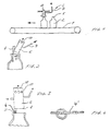
- the device consists of a transport device 1 on which the containers 2 to be checked are transported continuously and / or discontinuously.
- a suction device 3 is located above this conveyor.
- This advantageously consists of a nozzle-shaped injection pipe 4, which ends slightly above the plane of movement of the container mouths 5.
- the tubular body 6 is arranged, for example, according to FIG. 3, slightly with its lower edge 8 above the lower edge 9 of the injection nozzle 4.
- a laterally offset arrangement of the injection nozzle 4 to the center of the body 6 is particularly expedient.
- the container 2 transported on the transport device 1 is transported continuously or discontinuously below the suction device 3, a pulse of air being introduced into the container through the injection nozzle by means of pulse generators (not shown). This immediately causes the atmosphere therein to escape, which then gets into the tubular body 6 and is passed on to the analysis device (not shown), for example, by an analysis tube 7, which can also be switched in cycles.
- the residual air remaining in the tubular body 6 can escape relatively quickly through side or front openings 10.
- the suction device 3 consists of an elongated injection pipe 4 ', which extends over a longer distance of the container.
- the tubular body 6 is arranged at one point of this nozzle.
- the elongated nozzle 4 ' is expediently located at the edge of the container mouth, as a result of which a relatively large outlet area is formed for the air to be expelled.
- the nozzle is expediently directed in such a way that the air passes along the inner wall, leaving a relatively large remaining opening for the air to be emitted or pushed out.
- FIG. 3 also shows a nozzle 4 arranged at the edge of the container mouth, the containers moving into the plane of the drawing and, due to this arrangement, also leaving a large inlet cross section for the air to be absorbed from the container onto the tubular body 6.
- the nozzles 4 used can have certain configurations which allow particularly favorable flow guidance within the bottle. In this way, the container air to be expelled can escape relatively easily and be supplied for analysis.
- the suction device without one To use the blowing nozzle and to switch it on directly in the case of a container underneath by means of increased negative pressure, whereby an ambient bell is expediently provided, which allows a certain shielding from the ambient air.
- Containers 2 which do not contain an ongoing atmosphere, can then be separated out using known rejection systems.
Landscapes
- Health & Medical Sciences (AREA)
- Life Sciences & Earth Sciences (AREA)
- Chemical & Material Sciences (AREA)
- Engineering & Computer Science (AREA)
- Immunology (AREA)
- Physics & Mathematics (AREA)
- Analytical Chemistry (AREA)
- Biochemistry (AREA)
- General Health & Medical Sciences (AREA)
- General Physics & Mathematics (AREA)
- Pathology (AREA)
- Molecular Biology (AREA)
- Biomedical Technology (AREA)
- Mechanical Engineering (AREA)
- Food Science & Technology (AREA)
- Medicinal Chemistry (AREA)
- Sampling And Sample Adjustment (AREA)
Abstract
Claims (5)
- Procédé de prélèvement d'échantillons d'air dans des récipients (2) et d'envoi de ceux-ci vers un poste d'analyse, dans lequel au moyen d'une buse de soufflage (4), placée dans la zone d'une ouverture du récipient, des impulsions de pression d'un fluide sous pression sont introduites dans les récipients (2) et l'air des récipients, ainsi chassé, est recueilli, et dans lequel les récipients sont transportés, sur un dispositif de transport, devant un dispositif de prélèvement de gaz fixe, au moyen duquel une partie de l'air contenu dans chaque récipient (2) passant devant le dispositif de prélèvement peut être prélevée sans contact et acheminée vers le poste d'analyse, et à chaque récipient (2) sont imparties une ou plusieurs impulsions de pression d'un fluide sous pression, en vue de chasser l'air du récipient, et l'air du récipient ainsi chassé est acheminé vers le poste d'analyse, caractérisé en ce que l'air chassé du récipient est tenu à disposition, au-dessus de l'ouverture du récipient, à l'intérieur d'une enceinte de collecte (corps 6) et est aspiré de cette enceinte, en vue de l'analyse.
- Procédé selon la revendication 1, caractérisé en ce que le dispositif de prélèvement de gaz fixe agit par aspiration.
- Dispositif de prélèvement d'échantillons d'air dans des récipients (2) et d'acheminement de ceux-ci vers un poste d'analyse, comprenant une conduite d'aspiration (7), menant à celui-ci, qui se termine dans un dispositif d'aspiration, placé dans la zone des récipients, et comprenant un dispositif de transport, faisant passer les récipients devant le dispositif d'aspiration, caractérisé en ce que dans la zone de passage d'une ouverture de récipient, est placée une buse de soufflage (4), soumise à des impulsions de pression d'un fluide sous pression, et laquelle est associée au dispositif d'aspiration, de manière que l'air des récipients, chassé par les impulsions de pression introduites, peut être recueilli et acheminé vers le poste d'analyse et le dispositif d'aspiration est constitué d'un réservoir de stockage d'air (corps 6), auquel est raccordée la conduite d'aspiration (7), menant au poste d'analyse.
- Dispositif selon la revendication 3, caractérisé en ce que le dispositif d'aspiration est formé par un corps tubulaire (6), qui présente des ouvertures d'échange de gaz (10) sur son enveloppe.
- Dispositif selon l'une des revendications 3 ou 4, caractérisé en ce qu'une ou plusieurs buses de soufflage (4) sont prévues asymétriquement par rapport à l'axe des récipients et par rapport au dispositif de transport des récipients (2) et le dispositif d'aspiration est placé au-dessus de la section transversale d'écoulement principale de l'ouverture des récipients.
Applications Claiming Priority (3)
| Application Number | Priority Date | Filing Date | Title |
|---|---|---|---|
| DE4225984A DE4225984C2 (de) | 1992-08-06 | 1992-08-06 | Verfahren und Vorrichtung zur Entnahme von Luftproben aus Behältern |
| DE4225984 | 1992-08-06 | ||
| PCT/DE1993/000692 WO1994003287A1 (fr) | 1992-08-06 | 1993-08-04 | Procede et dispositif pour l'inspection de recipients transportes par un convoyeur |
Publications (2)
| Publication Number | Publication Date |
|---|---|
| EP0653964A1 EP0653964A1 (fr) | 1995-05-24 |
| EP0653964B1 true EP0653964B1 (fr) | 1997-05-28 |
Family
ID=6464958
Family Applications (1)
| Application Number | Title | Priority Date | Filing Date |
|---|---|---|---|
| EP93915691A Expired - Lifetime EP0653964B1 (fr) | 1992-08-06 | 1993-08-04 | Procede et dispositif pour l'inspection de recipients transportes par un convoyeur |
Country Status (4)
| Country | Link |
|---|---|
| EP (1) | EP0653964B1 (fr) |
| BR (1) | BR9306839A (fr) |
| DE (1) | DE4225984C2 (fr) |
| WO (1) | WO1994003287A1 (fr) |
Families Citing this family (9)
| Publication number | Priority date | Publication date | Assignee | Title |
|---|---|---|---|---|
| DE19505474C2 (de) * | 1995-02-17 | 1998-04-02 | Kronseder Maschf Krones | Verfahren und Vorrichtung zum Prüfen von Flaschen aus Kunststoff auf Kontaminationen |
| EP0747690A1 (fr) * | 1995-06-08 | 1996-12-11 | Elpatronic Ag | Dispositif de contrÔle des récipients |
| EP0752283A1 (fr) * | 1995-07-05 | 1997-01-08 | Elpatronic Ag | Procédé et dispositif pour l'inspection de conteneurs |
| EP0767368A3 (fr) * | 1995-10-06 | 1998-06-03 | Elpatronic Ag | Procédé et dispositif pour la prise d'échantillons gazeux provenant de récipients |
| DE10012446B4 (de) * | 2000-03-15 | 2007-06-14 | Tetra Laval Holdings & Finance S.A. | Verfahren zum Messen der Gasdurchlässigkeit einer Beschichtung auf einer Kunststoffwandung und Vorrichtung zur Durchführung des Verfahrens |
| DE202004008202U1 (de) * | 2004-05-18 | 2005-09-29 | Krones Ag | Vorrichtung zum Entnehmen von Gasproben aus Hohlgefäßen |
| DE102004034852B4 (de) * | 2004-07-19 | 2015-06-18 | Gunther Krieg | Verfahren und Vorrichtung zum Untersuchen von Behältern auf Fremdstoffe |
| DE102006009282B8 (de) * | 2006-03-01 | 2010-12-09 | Khs Gmbh | Vorrichtung zum Einbringen einer Inspektions- und/oder Kontrollflüssigkeit in Flaschen oder dergleichen Behälter |
| DE102020206159A1 (de) * | 2020-05-15 | 2021-11-18 | Gunther Krieg | Vorrichtung und Verfahren zum Untersuchen von Behältern auf Fremdstoffe |
Family Cites Families (9)
| Publication number | Priority date | Publication date | Assignee | Title |
|---|---|---|---|---|
| US3266292A (en) * | 1964-06-08 | 1966-08-16 | Nat Distillers Chem Corp | Method for detecting volatile organic contaminants in reusable containers |
| US4208372A (en) * | 1977-04-26 | 1980-06-17 | Bodenseewerk Perkin-Elmer & Co., Gmbh | Apparatus for generating and transferring a gaseous test sample to an atomic absorption spectrometer |
| GB1595672A (en) * | 1978-02-28 | 1981-08-12 | British American Tobacco Co | Headspace-sampling apparatus |
| DE3008762C2 (de) * | 1980-03-07 | 1983-02-17 | Weigel Handelsgesellschaft Mbh, 4300 Essen | Verfahren zum Prüfen von entleerten und vor ihrer Wiederverwendung zu reinigenden Bierfässern, insbesondere Keg-Fässern o.dgl. Behältern |
| AT392362B (de) * | 1987-07-02 | 1991-03-25 | Avl Verbrennungskraft Messtech | Eingabevorrichtung zum einbringen fluessiger oder gasfoermiger medien |
| US4791820A (en) * | 1987-07-31 | 1988-12-20 | Pharmacology & Toxicology Research Laboratory | Apparatus module for collection of volatiles from test sample |
| US4858767A (en) * | 1987-09-02 | 1989-08-22 | The Coca-Cola Company | Plastic container inspection process |
| US4880120A (en) * | 1987-09-02 | 1989-11-14 | The Coca-Cola Company | Plastic container inspection process |
| DE9114357U1 (de) * | 1991-11-18 | 1992-03-26 | Holstein Und Kappert Ag, 4600 Dortmund | Vorrichtung zur Fremdstoffinspektion von wiederverwendbaren Gefäßen |
-
1992
- 1992-08-06 DE DE4225984A patent/DE4225984C2/de not_active Revoked
-
1993
- 1993-08-04 BR BR9306839A patent/BR9306839A/pt not_active Application Discontinuation
- 1993-08-04 WO PCT/DE1993/000692 patent/WO1994003287A1/fr not_active Ceased
- 1993-08-04 EP EP93915691A patent/EP0653964B1/fr not_active Expired - Lifetime
Also Published As
| Publication number | Publication date |
|---|---|
| DE4225984A1 (de) | 1994-02-10 |
| DE4225984C2 (de) | 1995-06-01 |
| BR9306839A (pt) | 1998-12-08 |
| WO1994003287A1 (fr) | 1994-02-17 |
| EP0653964A1 (fr) | 1995-05-24 |
Similar Documents
| Publication | Publication Date | Title |
|---|---|---|
| EP0579952B1 (fr) | Procédé et dispositif pour contrôler l'état de propieté de bouteilles | |
| EP3890895B1 (fr) | Appareil de nettoyage pour appareil d'enduction | |
| DE2036262A1 (de) | Verfahren und Vorrichtung zum Einfügen eines Trennungsmediums in die Stromungsme dien einer Probenanalysiervornchtung | |
| WO2008058659A1 (fr) | Procédé d'inspection de bouteilles ou récipients analogues et poste de mesure pour un parcours d'inspection ou de contrôle de bouteilles ou récipients analogues | |
| DE4225984C2 (de) | Verfahren und Vorrichtung zur Entnahme von Luftproben aus Behältern | |
| DE102007055355A1 (de) | Reinigung von Bürsten | |
| DE2738570C2 (fr) | ||
| EP0534096B1 (fr) | Procédé et dispositif pour examiner des impuretés dans des récipients | |
| DD297714A5 (de) | Seitenstromsammelvorrichtung fuer zigarettenrauch | |
| EP0579055A1 (fr) | Procédé et dispositif pour contrôler l'état de propieté à l'aide de la spectrométrie de masse de bouteilles | |
| DE102012212809A1 (de) | Vorrichtung zur Reinigung von Bauteilen | |
| DE4427314C2 (de) | Vorrichtung zur Untersuchung von Behältern auf Fremdgase | |
| DE69722236T2 (de) | Inspektion von wasser-behältern | |
| DE2458234C3 (de) | Verfahren zum Reinigen einer Farbdüse einer Vorrichtung zum Spritzbedrucken eines porösen Stoffes sowie Vorrichtung zum Durchführen des Verfahrens | |
| DE9210531U1 (de) | Vorrichtung zur Inspektion von Gefäßen | |
| EP1495684B1 (fr) | Eclusage de tiges de filtre au dehors d'une conduite de transport | |
| DE9114357U1 (de) | Vorrichtung zur Fremdstoffinspektion von wiederverwendbaren Gefäßen | |
| DE19505474C2 (de) | Verfahren und Vorrichtung zum Prüfen von Flaschen aus Kunststoff auf Kontaminationen | |
| DE102011054208B4 (de) | Vorrichtung zum Absaugen eines Teilstroms aus einem Aerosol-Hauptstrom | |
| DE3315789C2 (fr) | ||
| DE4305799C2 (de) | Verfahren zum Überprüfen von geleerten wiederverwendbaren Behältern auf darin verbliebene Reststoffe | |
| DE102022114251A1 (de) | Vorrichtung mit Kennzeichnungsbereich und Reinigungsbereich | |
| DE20301224U1 (de) | Vorrichtung zur Untersuchung von Behältern | |
| DE102011086381A1 (de) | Getaktetes Wegblasen einer kontaminierten Gaswolke | |
| CH685124A5 (de) | Verfahren zum Behandeln eines Spinnbandendes und Vorrichtung zur Durchführung des Verfahrens. |
Legal Events
| Date | Code | Title | Description |
|---|---|---|---|
| PUAI | Public reference made under article 153(3) epc to a published international application that has entered the european phase |
Free format text: ORIGINAL CODE: 0009012 |
|
| 17P | Request for examination filed |
Effective date: 19941231 |
|
| AK | Designated contracting states |
Kind code of ref document: A1 Designated state(s): ES FR GB IT |
|
| 17Q | First examination report despatched |
Effective date: 19960417 |
|
| GRAG | Despatch of communication of intention to grant |
Free format text: ORIGINAL CODE: EPIDOS AGRA |
|
| GRAH | Despatch of communication of intention to grant a patent |
Free format text: ORIGINAL CODE: EPIDOS IGRA |
|
| GRAH | Despatch of communication of intention to grant a patent |
Free format text: ORIGINAL CODE: EPIDOS IGRA |
|
| GRAA | (expected) grant |
Free format text: ORIGINAL CODE: 0009210 |
|
| ITF | It: translation for a ep patent filed | ||
| AK | Designated contracting states |
Kind code of ref document: B1 Designated state(s): ES FR GB IT |
|
| PG25 | Lapsed in a contracting state [announced via postgrant information from national office to epo] |
Ref country code: ES Free format text: THE PATENT HAS BEEN ANNULLED BY A DECISION OF A NATIONAL AUTHORITY Effective date: 19970528 |
|
| GBT | Gb: translation of ep patent filed (gb section 77(6)(a)/1977) |
Effective date: 19970528 |
|
| ET | Fr: translation filed | ||
| PLBE | No opposition filed within time limit |
Free format text: ORIGINAL CODE: 0009261 |
|
| STAA | Information on the status of an ep patent application or granted ep patent |
Free format text: STATUS: NO OPPOSITION FILED WITHIN TIME LIMIT |
|
| 26N | No opposition filed | ||
| PGFP | Annual fee paid to national office [announced via postgrant information from national office to epo] |
Ref country code: FR Payment date: 20010530 Year of fee payment: 9 |
|
| PGFP | Annual fee paid to national office [announced via postgrant information from national office to epo] |
Ref country code: GB Payment date: 20010531 Year of fee payment: 9 |
|
| REG | Reference to a national code |
Ref country code: GB Ref legal event code: IF02 |
|
| PG25 | Lapsed in a contracting state [announced via postgrant information from national office to epo] |
Ref country code: GB Free format text: LAPSE BECAUSE OF NON-PAYMENT OF DUE FEES Effective date: 20020804 |
|
| GBPC | Gb: european patent ceased through non-payment of renewal fee |
Effective date: 20020804 |
|
| PG25 | Lapsed in a contracting state [announced via postgrant information from national office to epo] |
Ref country code: FR Free format text: LAPSE BECAUSE OF NON-PAYMENT OF DUE FEES Effective date: 20030430 |
|
| REG | Reference to a national code |
Ref country code: FR Ref legal event code: ST |
|
| PG25 | Lapsed in a contracting state [announced via postgrant information from national office to epo] |
Ref country code: IT Free format text: LAPSE BECAUSE OF NON-PAYMENT OF DUE FEES Effective date: 20050804 |