EP0654001B1 - Innenverpackung mit einer polsterstruktur aus geformter faserpulpe - Google Patents
Innenverpackung mit einer polsterstruktur aus geformter faserpulpe Download PDFInfo
- Publication number
- EP0654001B1 EP0654001B1 EP93918633A EP93918633A EP0654001B1 EP 0654001 B1 EP0654001 B1 EP 0654001B1 EP 93918633 A EP93918633 A EP 93918633A EP 93918633 A EP93918633 A EP 93918633A EP 0654001 B1 EP0654001 B1 EP 0654001B1
- Authority
- EP
- European Patent Office
- Prior art keywords
- pods
- ipc
- ribs
- rib
- structures
- Prior art date
- Legal status (The legal status is an assumption and is not a legal conclusion. Google has not performed a legal analysis and makes no representation as to the accuracy of the status listed.)
- Expired - Lifetime
Links
- 239000000835 fiber Substances 0.000 title claims abstract description 75
- 239000011105 molded pulp Substances 0.000 title claims abstract description 56
- 230000035939 shock Effects 0.000 claims abstract description 84
- 230000001133 acceleration Effects 0.000 claims abstract description 75
- 238000013461 design Methods 0.000 claims abstract description 49
- 230000003014 reinforcing effect Effects 0.000 claims abstract description 8
- 238000000034 method Methods 0.000 claims description 17
- 238000005452 bending Methods 0.000 claims description 15
- 230000013011 mating Effects 0.000 claims description 14
- 238000013016 damping Methods 0.000 claims description 10
- 230000000717 retained effect Effects 0.000 claims description 8
- 210000000038 chest Anatomy 0.000 claims description 7
- 230000033001 locomotion Effects 0.000 claims description 7
- 238000000465 moulding Methods 0.000 claims description 7
- 239000000725 suspension Substances 0.000 claims description 5
- 230000000284 resting effect Effects 0.000 claims description 4
- 235000020637 scallop Nutrition 0.000 claims description 4
- 241000237503 Pectinidae Species 0.000 claims description 3
- 230000036961 partial effect Effects 0.000 claims description 3
- 230000000737 periodic effect Effects 0.000 claims description 3
- 238000000151 deposition Methods 0.000 claims description 2
- 238000004891 communication Methods 0.000 claims 2
- 238000005304 joining Methods 0.000 claims 2
- 230000002401 inhibitory effect Effects 0.000 claims 1
- 238000004519 manufacturing process Methods 0.000 claims 1
- 230000000452 restraining effect Effects 0.000 claims 1
- 239000000047 product Substances 0.000 description 143
- 230000001012 protector Effects 0.000 description 26
- 239000002537 cosmetic Substances 0.000 description 23
- 239000000463 material Substances 0.000 description 23
- 230000006870 function Effects 0.000 description 20
- 239000004033 plastic Substances 0.000 description 20
- 229920003023 plastic Polymers 0.000 description 20
- 239000011521 glass Substances 0.000 description 18
- 235000013601 eggs Nutrition 0.000 description 16
- 238000010521 absorption reaction Methods 0.000 description 15
- 238000004806 packaging method and process Methods 0.000 description 11
- 238000006073 displacement reaction Methods 0.000 description 10
- 239000002657 fibrous material Substances 0.000 description 10
- 230000008859 change Effects 0.000 description 9
- 230000003321 amplification Effects 0.000 description 8
- 238000013459 approach Methods 0.000 description 8
- 238000003199 nucleic acid amplification method Methods 0.000 description 8
- 239000002002 slurry Substances 0.000 description 8
- 238000010998 test method Methods 0.000 description 8
- 239000002984 plastic foam Substances 0.000 description 6
- 230000002787 reinforcement Effects 0.000 description 6
- 238000009826 distribution Methods 0.000 description 5
- 230000000295 complement effect Effects 0.000 description 4
- 239000006260 foam Substances 0.000 description 4
- 238000003780 insertion Methods 0.000 description 4
- 230000037431 insertion Effects 0.000 description 4
- 230000001788 irregular Effects 0.000 description 4
- 239000004698 Polyethylene Substances 0.000 description 3
- 238000003491 array Methods 0.000 description 3
- 230000003796 beauty Effects 0.000 description 3
- 239000002655 kraft paper Substances 0.000 description 3
- -1 polyethylene Polymers 0.000 description 3
- 229920000573 polyethylene Polymers 0.000 description 3
- 229920002472 Starch Polymers 0.000 description 2
- 238000009825 accumulation Methods 0.000 description 2
- 230000008901 benefit Effects 0.000 description 2
- 230000005540 biological transmission Effects 0.000 description 2
- 150000001875 compounds Chemical class 0.000 description 2
- 238000010276 construction Methods 0.000 description 2
- 230000000694 effects Effects 0.000 description 2
- 238000004836 empirical method Methods 0.000 description 2
- 210000004709 eyebrow Anatomy 0.000 description 2
- 210000003128 head Anatomy 0.000 description 2
- 239000000203 mixture Substances 0.000 description 2
- 239000010813 municipal solid waste Substances 0.000 description 2
- 238000012856 packing Methods 0.000 description 2
- 239000000123 paper Substances 0.000 description 2
- 229920000642 polymer Polymers 0.000 description 2
- 239000008107 starch Substances 0.000 description 2
- 235000019698 starch Nutrition 0.000 description 2
- 238000012360 testing method Methods 0.000 description 2
- XLYOFNOQVPJJNP-UHFFFAOYSA-N water Substances O XLYOFNOQVPJJNP-UHFFFAOYSA-N 0.000 description 2
- 229920003043 Cellulose fiber Polymers 0.000 description 1
- 241000237509 Patinopecten sp. Species 0.000 description 1
- 229920005830 Polyurethane Foam Polymers 0.000 description 1
- 235000002595 Solanum tuberosum Nutrition 0.000 description 1
- 244000061456 Solanum tuberosum Species 0.000 description 1
- 239000011324 bead Substances 0.000 description 1
- 230000015572 biosynthetic process Effects 0.000 description 1
- 230000000903 blocking effect Effects 0.000 description 1
- 230000008878 coupling Effects 0.000 description 1
- 238000010168 coupling process Methods 0.000 description 1
- 238000005859 coupling reaction Methods 0.000 description 1
- 230000001627 detrimental effect Effects 0.000 description 1
- 238000007598 dipping method Methods 0.000 description 1
- 235000013399 edible fruits Nutrition 0.000 description 1
- 230000002708 enhancing effect Effects 0.000 description 1
- 239000004794 expanded polystyrene Substances 0.000 description 1
- 210000000887 face Anatomy 0.000 description 1
- 235000013305 food Nutrition 0.000 description 1
- 230000005484 gravity Effects 0.000 description 1
- 238000007654 immersion Methods 0.000 description 1
- 230000003116 impacting effect Effects 0.000 description 1
- 238000002955 isolation Methods 0.000 description 1
- 230000007774 longterm Effects 0.000 description 1
- 230000014759 maintenance of location Effects 0.000 description 1
- 239000002985 plastic film Substances 0.000 description 1
- 229920006255 plastic film Polymers 0.000 description 1
- 229920002285 poly(styrene-co-acrylonitrile) Polymers 0.000 description 1
- 229920006327 polystyrene foam Polymers 0.000 description 1
- 239000011496 polyurethane foam Substances 0.000 description 1
- 230000009290 primary effect Effects 0.000 description 1
- 230000008569 process Effects 0.000 description 1
- 238000004537 pulping Methods 0.000 description 1
- 239000002994 raw material Substances 0.000 description 1
- 230000009467 reduction Effects 0.000 description 1
- 239000002910 solid waste Substances 0.000 description 1
- 238000003860 storage Methods 0.000 description 1
- 239000013589 supplement Substances 0.000 description 1
- 238000012956 testing procedure Methods 0.000 description 1
- 235000013311 vegetables Nutrition 0.000 description 1
Images


Classifications
-
- B—PERFORMING OPERATIONS; TRANSPORTING
- B65—CONVEYING; PACKING; STORING; HANDLING THIN OR FILAMENTARY MATERIAL
- B65D—CONTAINERS FOR STORAGE OR TRANSPORT OF ARTICLES OR MATERIALS, e.g. BAGS, BARRELS, BOTTLES, BOXES, CANS, CARTONS, CRATES, DRUMS, JARS, TANKS, HOPPERS, FORWARDING CONTAINERS; ACCESSORIES, CLOSURES, OR FITTINGS THEREFOR; PACKAGING ELEMENTS; PACKAGES
- B65D43/00—Lids or covers for rigid or semi-rigid containers
- B65D43/14—Non-removable lids or covers
- B65D43/16—Non-removable lids or covers hinged for upward or downward movement
- B65D43/162—Non-removable lids or covers hinged for upward or downward movement the container, the lid and the hinge being made of one piece
-
- B—PERFORMING OPERATIONS; TRANSPORTING
- B65—CONVEYING; PACKING; STORING; HANDLING THIN OR FILAMENTARY MATERIAL
- B65D—CONTAINERS FOR STORAGE OR TRANSPORT OF ARTICLES OR MATERIALS, e.g. BAGS, BARRELS, BOTTLES, BOXES, CANS, CARTONS, CRATES, DRUMS, JARS, TANKS, HOPPERS, FORWARDING CONTAINERS; ACCESSORIES, CLOSURES, OR FITTINGS THEREFOR; PACKAGING ELEMENTS; PACKAGES
- B65D21/00—Nestable, stackable or joinable containers; Containers of variable capacity
- B65D21/02—Containers specially shaped, or provided with fittings or attachments, to facilitate nesting, stacking, or joining together
- B65D21/0233—Nestable containers
-
- B—PERFORMING OPERATIONS; TRANSPORTING
- B65—CONVEYING; PACKING; STORING; HANDLING THIN OR FILAMENTARY MATERIAL
- B65D—CONTAINERS FOR STORAGE OR TRANSPORT OF ARTICLES OR MATERIALS, e.g. BAGS, BARRELS, BOTTLES, BOXES, CANS, CARTONS, CRATES, DRUMS, JARS, TANKS, HOPPERS, FORWARDING CONTAINERS; ACCESSORIES, CLOSURES, OR FITTINGS THEREFOR; PACKAGING ELEMENTS; PACKAGES
- B65D5/00—Rigid or semi-rigid containers of polygonal cross-section, e.g. boxes, cartons or trays, formed by folding or erecting one or more blanks made of paper
- B65D5/42—Details of containers or of foldable or erectable container blanks
- B65D5/44—Integral, inserted or attached portions forming internal or external fittings
- B65D5/50—Internal supporting or protecting elements for contents
- B65D5/5028—Elements formed separately from the container body
- B65D5/503—Tray-like elements formed in one piece
-
- B—PERFORMING OPERATIONS; TRANSPORTING
- B65—CONVEYING; PACKING; STORING; HANDLING THIN OR FILAMENTARY MATERIAL
- B65D—CONTAINERS FOR STORAGE OR TRANSPORT OF ARTICLES OR MATERIALS, e.g. BAGS, BARRELS, BOTTLES, BOXES, CANS, CARTONS, CRATES, DRUMS, JARS, TANKS, HOPPERS, FORWARDING CONTAINERS; ACCESSORIES, CLOSURES, OR FITTINGS THEREFOR; PACKAGING ELEMENTS; PACKAGES
- B65D81/00—Containers, packaging elements, or packages, for contents presenting particular transport or storage problems, or adapted to be used for non-packaging purposes after removal of contents
- B65D81/02—Containers, packaging elements, or packages, for contents presenting particular transport or storage problems, or adapted to be used for non-packaging purposes after removal of contents specially adapted to protect contents from mechanical damage
- B65D81/05—Containers, packaging elements, or packages, for contents presenting particular transport or storage problems, or adapted to be used for non-packaging purposes after removal of contents specially adapted to protect contents from mechanical damage maintaining contents at spaced relation from package walls, or from other contents
- B65D81/127—Containers, packaging elements, or packages, for contents presenting particular transport or storage problems, or adapted to be used for non-packaging purposes after removal of contents specially adapted to protect contents from mechanical damage maintaining contents at spaced relation from package walls, or from other contents using rigid or semi-rigid sheets of shock-absorbing material
- B65D81/133—Containers, packaging elements, or packages, for contents presenting particular transport or storage problems, or adapted to be used for non-packaging purposes after removal of contents specially adapted to protect contents from mechanical damage maintaining contents at spaced relation from package walls, or from other contents using rigid or semi-rigid sheets of shock-absorbing material of a shape specially adapted to accommodate contents, e.g. trays
Definitions
- This invention relates to interior package cushioning (IPC) structures for protecting products shipped in a package from mechanical shock caused by corner drops, edge drops, face drops and horizontal impacts of the package, and from vibrations imparted by different transport modes during shipping and distribution.
- the invention provides new molded pulp fiber IPC structures which replace plastic foam interior package cushioning material.
- the IPC structures are molded with new crushable cushioning structures in new geometrical configurations designed to absorb impact shocks, critically damp vibrations, resist bending and hinging, support and direct loading and stacking forces around product containing cavities, and generally cushion and protect products shipped in a package.
- the molded pulp fiber IPC structure invention provides improved interior package cushioning characteristics in comparison with conventional plastic and plastic foam structures and conventional molded pulp fiber structures.
- plastic cushioning materials include a variety of polyethylene foams, moldable polyethylene copolymer foam, expanded polyethylene bead foam, styrene acrylonitrile copolymer foam, polystyrene foams, polyurethane foams, etc.
- plastic materials and plastic foams may be molded in place or molded to specific interior package cushioning structure shapes.
- the plastic may be formed in pieces to provide loosefill. Sheets of plastic film may be bonded together encapsulating bubbles of air to provide cushioning material.
- plastic interior package cushioning materials are described for example in Brandenburg and Lee, Fundamentals of Packaging Dynamics , MTS Systems, P.O.
- plastic cushioning materials There are two major disadvantages associated with plastic cushioning materials and plastic interior package cushioning structures. Disposable packaging is a major contributor to the nation's municipal solid waste. It is estimated that packaging constitutes approximately one third by volume of all municipal solid waste and 8% of this amount is made up of the cushioning materials. The plastic cushioning materials are generally neither biodegradable nor compostable and therefore remain a long term component of the solid waste accumulation problem.
- plastic interior package cushioning structures are characterized by irreducible spring constant parameters that may be detrimental to product cushioning and to product protection from mechanical shock and vibration during shipping and distribution of packaged products.
- Plastic foam materials may be inherently limited in the reduction that can be achieved for rebound, coefficient of restitution, and elasticity.
- the plastic cushioning materials may be implicated in resonance conditions which increase the shock amplification factor of the package system and link the shock acceleration, change of velocity and displacement with a product contained in the package.
- the plastic interior package cushioning structures of the product/package system may, if such resonance conditions occur, contribute to undesirable shock transmission and shock amplification.
- the shock amplification factor introduced by plastic cushioning materials may actually increase the shock accelerations, changes in velocities, and displacements experienced by a product.
- the plastic interior package cushioning structures of the package/product system may under resonance conditions contribute to vibration magnification or transmissibility.
- the vibration magnification factor of plastic cushioning materials may result in a multiples increase in the vibration accelerations, changes in velocity, and displacements experienced by the packaged product. Again, it is the characteristics of plastic cushioning materials that contribute to resonance conditions enhancing the vibration magnification factor and linking the forcing vibrations of the transport mode with a product inside the package.
- plastic foam interior package cushion structures Another disadvantage of plastic foam interior package cushion structures is that the inherent rebound, coefficient of restitution, modules of elasticity, and spring constant characteristics of the plastic materials are an impediment to achieving critical damping structures for critically damping mechanical shocks and shipping vibrations.
- the plastic foam filled spaces conventionally used in product packaging may contribute to conditions of overdamping or underdamping with excessive transmissibility of mechanical shock and vibration accelerations, changes in velocity, and displacements to the packaged product.
- Molded pulp fiber has previously been used in packaging structures described in U.S. Patents 5,096,650; 4,742,916; 4,480, 781; 4,394,214; 3,718,274; 3,700,096; 3,286,833; 3,243,096; 2,704,268.
- Keyes Fiber Company College Avenue, Waterville, Maine 04901 manufactures molded fiber fluorescent tube trays used in shipping fluorescent tubes stacked in a package.
- the fluorescent tube trays are formed with recesses complementary with the cylindrical fluorescent tubes.
- these prior art fluorescent tube trays function only as dividers for preventing glass to glass contact.
- the recesses only perform an indexing function for separating the tubes from one another.
- the Keyes Fiber Company fluorescent tube trays do not perform a stacking function in the sense of directing stacking forces around product receiving recesses. Rather the tube trays do not contact each other and the stacking forces bear directly on the fluorescent tubes. Furthermore the fluorescent tube trays do not perform a design cushioning or design protection function. They are not designed to crush and absorb energy at package accelerations caused by mechanical shock and vibration which approach a specified design threshold or limit of mechanical shock and vibration acceleration at which damage or breakage may occur to a sensitive element of the fluorescent tube products shipped in the package. The utility of such fluorescent tube trays is exhausted by the dividing, indexing and separating functions only.
- Egg crates are typically formed with egg pockets for containing, indexing and separating the eggs. Resilient pillow pads or buttons may be formed in the bottom of egg pockets to "cradle" eggs in the egg pockets.
- the egg crate cover rests on "posts" formed at the intersections between egg pockets for bearing stacking forces so that egg crates may be stacked.
- the egg pockets and related structures of a conventional egg crate are not designed to crush and absorb energy for protecting eggs at package design limit or design threshold accelerations.
- Conventional egg crates do not incorporate crushable structures intended to crush and absorb energy at package accelerations from mechanical shock and vibration which approach a specified design threshold or limit at which damage or breakage may occur to eggs.
- the primary purpose for egg crates as for molded pulp fiber apple flats and other molded pulp fiber trays for food products is for indexing, dividing, orienting, and separating products from contact with each other.
- the present invention is directed to molded pulp fiber packaging structures specifically intended, designed, and constructed to meet predictable and reliable design specifications and cushioning requirements for protecting products shipped in a package from specified levels of mechanical shock and vibration accelerations at which damage or breakage may occur to a sensitive element of products shipped in a package.
- Packaging structures have also been manufactured by so-called “slush molding” from a Kraft fiber based raw material slurry.
- Such Kraft fiber slush molded packaging structures are manufactured by Fibercel Inc. of Portville, New York.
- the heavy Kraft fiber structures are vacuum molded by "candle dipping", that is by immersion of the vacuum molding head multiple times in the slurry.
- a disadvantage of the slush molded package structures is that they are relatively rigid structures that are not predictably crushable. They cannot crush and absorb energy at reliable specified design limits or thresholds of mechanical shock and vibration acceleration. They are primarily intended for blocking and bracing and also are not suitable for nesting because of the mass of the slush molded structures.
- GB-A-870,704 describes bottle containers for a row of side-by-side bottles with the neck of each bottle adjacent the bottom of the next bottle.
- US-A-2,936,922 describes molded pulp packing trays, adapted to be disposed between layers of fruit in a packing case.
- US Des. 86,061 shows a perspective view of an open and a closed pack for fragile articles.
- US-A-1,960,279 describes holders or trays in which to pack fragile articles for storage or transportation.
- the molded pulp and molded fiber IPC structures may be molded from recycled cellulose fibers to provide environmentally sound recyclable, biodegradable, and compostable interior package cushioning structures.
- Another object of the invention is to construct new interior package cushioning structures from natural materials such as fiber having inherently lower properties and parameters of rebound, coefficient of restitution, modulus of elasticity, and spring constant than is typically characteristic of plastic polymer molecules.
- the new IPC structure molded natural fiber material affords improved opportunity for avoiding shock amplification or vibration magnification.
- the new relatively inelastic fiber materials are particularly suited for critically damping mechanical shocks and shipping vibrations.
- a further object of the invention is to provide new molded hollow crushable cushioning structures for absorbing and damping shocks and vibrations by the strategic shapes, configurations and placement of the hollow crushable cushioning structures as well as the inelastic properties of the materials composing the structures.
- the invention relies upon the novel cushion structure shapes and configurations to achieve the desired characteristics of reduced rebound, coefficient of restitution, modulus of elasticity, and spring constant in addition to the inherent inelastic molecular properties of the material itself.
- the invention seeks to achieve a new result using molded pulp fiber materials including recycled fiber.
- the objective is to provide molded pulp fiber interior package cushioning (IPC) structures that predictably and reliably meet design specifications and cushioning requirements for protecting a product shipped in a package from specified mechanical shock and vibration accelerations.
- the invention must typically protect a sensitive element of a product which is subject to damage or breakage if shock acceleration or vibration acceleration is transmitted to the product and sensitive element equal to or grater than a design limit or threshold.
- This design limit is typically specified in "g's", i.e., multiples of the acceleration "g" due to gravity on the Earth.
- the invention meets such design specifications and requirements by deploying geometric shapes and configurations in molded pulp fiber IPC structures which provide the requisite crushability and cushioning absorption of energy at shock accelerations and vibration accelerations imparted to a package approaching the design threshold or design limit of shock acceleration or vibration acceleration at which damage or breakage may occur to the sensitive element of a product.
- the invention is intended to meet such design requirements reliably and predictably according to ASTM test procedures and standards, and test procedures of the National Safe Transit Association (NSTA).
- NSTA National Safe Transit Association
- IPC Structure is a molded pulp fiber internal or interior package cushioning structure used to protect products during shipping in a package.
- the IPC structure is generally formed with a cavity to receive a product.
- Cushioning structures such as crushable ribs, pods, rows of pods, podded ribs, etc. are molded in the IPC structure around the cavity.
- IPC structures also include corner protectors and insert protectors which are not necessarily formed with a cavity and which are added to a package to provide supplementary protection of products shipped in a package.
- Package A package is the external container for shipping products. Products are first placed in the cavities of IPC structures. The product enveloping IPC structures are then stacked in a package although an individual or single product enclosed or surrounded by IPC structures may also be shipped in a package.
- Cavity is a space with walls molded in the molded pulp fiber IPC structure to receive and hold a product to be shipped in a package.
- the cavity generally has an unusual or irregular configuration, custom shaped to accommodate a particular product.
- the cavity walls may incorporate shapes such as shelves, gables, shallow cones, and arches which reinforce the cavity walls to protect a product and transmit stacking and loading forces around a product in the cavity.
- the cavity is generally surrounded by one or more of the new molded pulp fiber crushable cushioning structures such as ribs, pods, rows of pods, podded ribs, etc. molded in the IPC structure.
- Ribs are elongate hollow ridges molded in the IPC structure, extending or “bridging” between different locations on the IPC structure for "crushable" reinforcement between the locations. Ribs are positioned around a cavity to provide product protection from mechanical shock, vibrations, and stacking and loading forces, and sometimes to avert bending or hinging. Ribs are crushable structures which crush and absorb energy at package accelerations from mechanical shock and vibration which approach a specified design threshold or limit of mechanical shock and vibration acceleration at which damage or breakage may occur to a sensitive element of a product shipped in the package.
- Anti-hinge ribs are ribs formed at locations on the IPC structure which may be vulnerable to bending or hinging in order to resist such bending or hinging. Anti-hinge ribs may also perform a beam-like function in supporting a product retained in a cavity.
- Pods Pods are hollow recesses or wells substantially symmetrical in cross section molded with selected depths in the IPC structure. Pods are positioned at locations around a cavity to enhance product protection from mechanical shock, vibrations, and stacking and loading forces. Pods are generally tapered in cross section from a greater dimension at the opening of the recess or well to a smaller dimension at the bottom of the recess or well. Pods are crushable structures designed to crush and absorb energy at package accelerations from mechanical shock and vibration which approach a specified design threshold or limit of shock and vibration acceleration at which damage or breakage may occur to a sensitive element of a product shipped in the package.
- a row of pods is a linear sequence of at least three pods spaced closely together with the distance between pods less than the width of a pod.
- An array of pods is a set of at least three pods spaced closely together not necessarily in a linear sequence.
- Fillets may be deposited in the valleys between the outside of adjacent pods to provide increased crush resistance, resistance to bending or hinging at joints between pods, for increased product protection, and for transmitting lateral forces around a cavity. Fillets may be used to adjust the crushability of a crushable row or array of pods over a range from high compliance crushing to structural rigidity according to the added mass of material.
- the fillets may also perform a denesting function to prevent locking of nested IPC structures.
- Podded rib is a rib formed with a row of at least three rib pods along the rib. The depth of the rib pod is shallower than the depth of the rib. This distinguishes a podded rib from a row of pods. Fillets may be deposited between the rib pods of a podded rib as well as between the pods of a row of pods.
- a podded rib provides a rib which affords increased crush protection, increased product protection, diversion of stacking and loading forces, and resistance to bending and hinging.
- Fillet A fillet or gusset is an accumulation of molded pulp fiber deposited in the valley between the outsides of adjacent pods in a row of pods or a podded rib.
- Fillets can perform a reinforcing function for increased product protection, for transmitting stacking and loading forces, and for increased crush resistance and resistance to bending or hinging at joints between pods.
- Fillets can be used to adjust the level of crushability of crushable structures over a range from high compliance crushing and cushioning to structural rigidity. Fillets also provide a denesting function to avert locking of nested IPC structures.
- Posts are pods of extended depth greater than the depth or width of a cavity. Posts generally perform a post-like function by supporting a product packed in a cavity and by transmitting stacking and loading forces around a product containing pocket or cavity to the base of a package. Posts are also crushable structures for responding to mechanical shock accelerations and vibration accelerations approaching a design limit or threshold for cushioning and protecting a product by crushing and by absorbing energy.
- Shelves are effectively half ribs taken in the elongate direction of a rib. Shelves are molded in the IPC structure and form a step structure between one level of an IPC structure and another level. Shelves are generally formed in the wall of a cavity to support a product, reinforce the cavity, transmit stacking and loading forces around the product, and increase product protection.
- Scalloped edges or reinforced edges are edges of a molded pulp fiber IPC structure formed with periodic scallops or depressions to impart edge strength for increased resistance to crushing, increased product protection, and for transmitting lateral forces.
- Stacking ribs and pods are ribs and pods molded in the IPC structure at locations arranged for complementary abutting contact when IPC structures loaded with products are stacked back to back in a package.
- the stacking ribs and pods transmit stacking and loading forces around the product containing cavities to the base of the package.
- Nesting is the back to front interfitting placement of IPC structures on top of each other when facing in the same direction and without products in the respective cavities. IPC structures are nested to conserve space for shipping the internal package cushioning structures to product manufacturers for use in shipping products.
- Stacking is the interfitting back to back placement of IPC structures on top of each other in a package after loading products in the cavities. In stacking, the stacked IPC structures face in opposite directions. The manufacturer stacks product loaded IPC structures in a package for shipping.
- a friction fit or crush fit pocket or cavity is a pocket formed with protruding crush ribs that protrude into the pocket and define a width dimension sized slightly smaller than a width dimension of a product to be inserted in the pocket.
- a crush rib is a rib formed to protrude into a friction fit pocket and constructed to crush slightly when the product is pushed into the friction fit pocket.
- the crush rib and friction fit pocket combination has been found to impart excellent vibration damping characteristics to the package/product system for critically damping vibrations originating from the transport mode, for preventing vibration magnification, and for isolating a product from vibrations. When the product is forcibly inserted in the friction fit pocket, the pocket also expands stressing and partially separating fibers and further contributing to vibration isolation and protection of the product in the crush fit pocket.
- Suspended Pocket or Suspension Pocket A suspended pocket is a pocket or cavity suspended between two or more ribs, pods, or similar support structures to support a product in the pocket by suspension.
- the suspended pocket suspends and protects products so that no part of the product or suspending pocket touches the external container package or any other IPC structure during shipping and handling.
- a rib cage is a network of a plurality of intersecting crushable ribs extending in two or three orthogonal directions or axes around at least a portion of a cavity for protecting a product in a cavity from mechanical shock and vibrations.
- Mechanical Shock Mechanical shock is the abrupt motion imparted to a package by impact of the package with the floor in corner drops, edge drops and face drops, as well as by horizontal impacts during shipping and handling. Mechanical shock is characterized by rapid change in the acceleration, velocity and displacement of the package.
- a package shock may typically impart to the package a shock acceleration in the range of, for example, 150 g's (where g is the acceleration due to the earth's gravitational field) with a short duration in the range of for example 20 milliseconds (mS).
- Shock acceleration, change in velocity, and deflection generally refer to the maximum acceleration, change in velocity, and deflection or displacement imparted to the package by a shock pulse.
- Shock Amplification and Shock Transmissibility Shock amplification is the multiplication or enhancement of shock acceleration, change in velocity and deflection caused by the spring constant characteristics of the package/product system and particularly the interior package cushioning structures of the product/package system at or near a resonance condition.
- a resonance condition occurs when the frequency (f 2 ) of the shock pulse and a natural frequency (f 1 ) of the product package system substantially coincide.
- the amplification factor is the multiple increase in maximum shock acceleration, change in velocity and deflection experienced by a product or transmitted to a product by a package/product system and in particular by the interior package cushion structures as a result of a mechanical shock applied to a package.
- Shock amplification by the package/product system is also referred to as shock transmissibility of the package/product system.
- Vibrations are the periodic or random motions imparted to a package by vehicles and transport modes during shipping and distribution of the package.
- the vibration acceleration, velocity, and displacement generally refer to the peak acceleration, velocity, and displacement imparted to a package by the shipping vibrations.
- Vibration accelerations are generally measured in g's, (units of the earth's gravitational acceleration).
- Vibration Magnification and Vibration Transmissibility is the multiplication or enhancement in vibration acceleration, change in velocity, and displacement caused by the spring constant characteristics of the package/product system and particularly by the interior package cushioning structures of the product/package system at or near a resonance condition.
- a resonance condition occurs when the frequency (f f ) of the forcing vibrations of the transport mode and a natural frequency (f n ) of the product/package system substantially coincide.
- the vibration magnification factor is the multiple increase in vibration acceleration, change in velocity, and displacement experienced by a packaged product and links the vibrations of the transport mode to the product inside the package/product system.
- Crushable Structure including ribs and pods according to the invention are hollow geometrical shapes and configurations distributed around product receiving cavities of IPC structures.
- the crushable structures are designed for crushability and cushioning absorption of energy at accelerations imparted to a package by mechanical shock and vibration approaching the design limit or threshold of shock and vibration accelerations at which damage or breakage may occur to a sensitive element of a product shipped in the package.
- the hollow crushable structures of molded pulp fiber material according to the invention are effectively inelastic upon crushing and cushioning absorption of energy thereby effectively eliminating rebound and coefficient restitution. Below the design limit or threshold, however the crushable structures retain some memory and recoverability to maintain the structure and integrity of the IPC structure.
- Crushability at or approaching the design limit in g's refers to the capability of crushing by fiber breaking, tearing, fracturing and pulling apart. Crushability may be viewed as a design characteristic selected or specified over a range from highly compliant crushing to structural rigidity.
- the crushability of crushable structures according to the invention is established by empirical methods to achieve product protection at the specified design limits or threshold of shock and vibration acceleration typically in a range from 20 g's to 200 g's.
- the invention provides a new structure for interior package cushioning to protect products shipped in a package.
- the interior package cushioning (IPC) structure is molded from pulp fiber and preferably recycled pulp fiber.
- the IPC structure defines a cavity or pocket custom shaped for receiving and holding a product to be shipped.
- a plurality of structural ribs are incorporated in the IPC structure in the form of elongate hollow ridges molded in the IPC structure extending between different locations on the IPC structure for crushable reinforcement of the IPC structure between the locations.
- the IPC structure incorporates different ribs extending in at least two orthogonal directions or axes relative to each other and intersecting with each other to form a crushable "rib cage". In some examples the ribs extend in three orthogonal directions along three axes with intersecting ribs.
- the ribs are positioned and distributed around at least a portion of the cavity of the IPC structure for protecting a product in the cavity from mechanical shock caused by corner drops, edge drops, face drops, and horizontal impacts of a package, for damping vibrations imparted by transport modes, and for transmitting stacking and loading forces around the cavity.
- a feature of the invention is that the hollow ribs are crushable structures constructed for crushing and absorbing energy at accelerations caused by mechanical shock and vibration imparted to a package which approach a specified design limit or threshold acceleration at which damage or breakage may occur to a sensitive element of a product shipped in the package.
- the crushability and inelastic cushioning absorption of energy is established by empirical methods to assure predictable and reliable protection of products at the specified design limit of mechanical shock acceleration and vibration acceleration.
- the IPC structure also incorporates a plurality of structural pods in the form of hollow recesses or wells substantially symmetrical in cross section and molded with selected depths in the IPC structure at different locations.
- the pods are positioned and distributed around the cavity to provide additional protection for a product in the cavity from mechanical shock, vibrations, and stacking and loading forces.
- the pods are also crushable structures constructed for crushing and cushioning absorption of energy at mechanical shock accelerations and vibration accelerations approaching a design limit or threshold in "g's".
- the structural pods may be arranged in a row of pods having at least three pods closely spaced in a linear sequence.
- the row of pods is positioned on the IPC structure to enhance product protection and to resist crushing.
- the molded pods are tapered from a greater dimension at the opening of the recess or well of the pod to a smaller dimension at the bottom of the recess or well.
- the row of pods may be formed in a rib to form a podded rib of a row of at least three rib pods.
- the row of rib pods reinforces the podded rib to provide additional product protection by sequential crushability and sequential crushing and absorption of energy from a single impact or multiple impacts.
- Pods may also be formed in arrays to form a reinforced two dimensional grid. Rows of pods and arrays of pods may permit a package to bear multiple impacts at the design limit or threshold of "g's" while protecting the product from breakage or damage.
- fillets of molded pulp fiber are deposited in valleys between the outsides of adjacent pods to increase resistance to crushing and bending or hinging at the valleys between pods. Such fillets are used to add an additional level of crushable protection to the packaged products.
- the fillets are also used to adjust the crushability of crushable structures.
- Ribs and pods molded in the IPC structure may be arranged for nesting of a plurality of IPC structures facing in the same direction thereby minimizing the space requirements for shipping the IPC structures without products in the cavities.
- the fillets also function as denesting fillets performing a denesting function to prevent locking of IPC structures.
- Denesting lugs may also be molded in the IPC structures to prevent locking engagement of nested IPC structures.
- a variety of rib and pod structures are provided for performing a variety of functions. For example stacking ribs and pods are arranged for back to back mating of ribs and pods of adjacent IPC structures. The ribs and pods on the outside of one IPC structure rest on the ribs and pods on the outside of another for stacking of products retained in the cavities of the IPC structures. The ribs and pods are arranged to transmit stacking forces and loading forces through ribs and pods around the product containing cavities to the base of a package.
- ribs include anti-hinge ribs formed at locations on the IPC structure to counteract hinging or bending motion at such locations.
- Crush ribs are formed to protrude into friction fit cavities to define a pocket width less than a width dimension of a product to be received in the pocket for imparting critical vibration damping and vibration isolating characteristics.
- Support ribs are provided to support a product in a suspended pocket between two locations.
- Elongate pods having a depth dimension greater than a cavity provide posts for transmitting stacking and loading forces around the cavity.
- a variety of crushable reinforcing cavity shapes are also disclosed.
- the invention also provides IPC structures not necessarily formed with a cavity such as a corner protector structure to supplement the interior package cushioning.
- the molded pulp fiber IPC corner protector structure is constructed for positioning at corners of a package for protecting a product from mechanical shock, vibrations, and stacking and loading forces and for providing energy absorbing and cushioning crushability at the corners.
- the corner protector structure incorporates an array of a plurality of structural pods molded in the IPC corner protector structure in the form of hollow recesses or wells substantially symmetrical in cross section and molded with selected depths in the IPC corner protector structure. The pods are tapered from a greater dimension at the opening of the recess or well to a smaller dimension at the bottom of the recess or well.
- the array of pods includes a set of first pods molded with a first selected depth, and a set of second pods molded with a second selected depth less than the first selected depth.
- the array of pods affords a lesser resistance to crushing or lower acceleration level crushability by the first set of pods for absorbing shocks and vibrations, and a greater resistance to crushing and higher acceleration level crushability after the first set of pods are crushed to the depth of the second set of pods. Additional sets of pods may be incorporated in the array affording additional levels of crushability.
- the array of pods therefore provides an IPC corner protector structure with at least two different sequential levels of resistance to crushing and crushability by mechanical shocks, vibrations, and stacking and loading forces.
- the array of pods in the IPC corner protector structure may be formed with fillets of molded pulp fiber deposited in the valleys between the outsides of adjacent pods to provide yet a third level or greater level of crushability with increased resistance to crushing and to bending or hinging at the valleys between pods.
- the invention also provides cavity IPC structures incorporating the array of multilevel pods for multiple levels of crushability.
- This feature of the invention is particularly applicable for IPC structures used in shipping heavy products with delicate or sensitive elements such as television sets and electronic equipment.
- arrays of multilevel pods are molded directly in the IPC structure and distributed around the product receiving cavity.
- the array of pods with multiple depths or lengths are designed for crushing and absorbing energy at multiple design limits or thresholds of mechanical shock acceleration and vibration acceleration imparted to the package.
- the IPC structures respond by crushing at the successive levels. Furthermore fillets between the pods may be deposited to afford a final level of crushability.
- the invention provides crushable structures in the form of a variety of hollow geometrical shapes and configurations formed in molded IPC structures for crushing and cushioning absorption of energy at design limits and thresholds of mechanical shock accelerations and vibration accelerations imparted to a package.
- the crushable structures afford reliable and predictable product protection at the design limits and requirements.
- the crushability and cushioning absorption of energy is established by empirical and heuristic methods and procedures and ultimately satisfies design requirements for product protection according to ASTM and NSTA test procedures.
- the adjustable parameters of the crushable structures such as ribs and pods available for adjustment to achieve design requirements for protection at specified g levels include the thickness of the molded pulp fiber walls, referred to as the gauge or caliper of the molded pulp fiber walls or shelves.
- the caliper is generally in the range of 0.08 - 0.51 cm (0.030 - 0.200 inches) and more typically in the range of 0.08 - 0.24 cm (0.030 -0.095 inches). Fillets may be used to increase the caliper or gauge to the higher level thickness of the range at selected locations such as the valleys between the outsides of pods. Varying the caliper of the shell and adding fillets may be used to increase material rigidity and change the crushability of the crushable structure over a range from compliant cushioning to structural rigidity.
- crushability Other factors in determining crushability include the depth and area of the crushable structures. Factors in determining the design crushability include the weight, size and area of the product to be protected, design drop height and design limit or threshold in g's at which breakage or damage may occur to a sensitive element of the product. Contents of the molded pulp fiber including fiber length and moisture content may also be a factor.
- the molded pulp fiber IPC structures of the invention are generally formed with a final moisture content of about 10%.
- the internal package cushioning structures are vacuum molded from a slurry of recycled fiber.
- the slurry of pulp fiber is formed by a major portion of newspaper, a minor portion of white ledger office paper to enhance fiber length, a vegetable base starch for a binding compound, and water. The mixture is repulped to provide the slurry of recycled pulp fiber from which the IPC structures are molded by vacuum molding machines.
- one recipe for a molded pulp fiber slurry according to the invention is as follows. 31,75 Kg (seventy pounds) of newspaper/newsprint, 13,6 Kg (thirty pounds) of white ledger office paper, 0,9 Kg (two pounds) of potato base starch, and 0,9 cubic meter (two hundred forty gallons) of water are added to a rotary pulping tank. The rotor pulps the mixture for example for twenty minutes after which it is transferred to a holding tank for use as the vacuum molding slurry.
- the vacuum molding heads immersed in the slurry are generally of the type with a perforated screen surface for distributing negative pressure for molding and positive pressure for releasing a molded article.
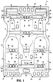
- FIGs. 1-4 An internal package cushioning structure for shipping bottles in a bottle shipping package is illustrated in Figs. 1-4.
- the internal package cushioning structure is particularly adapted for shipping wine bottles in a wine bottle shipping package.
- the lower half 10 of the IPC structure is illustrated in Figs. 1,1A and 2 and is formed with half cavities 12 for receiving three wine bottles in a single tier or level.
- An upper half of the IPC structure not shown in Figs. 1 and 2, but identical to the lower half IPC structure 10 in a mirror image orientation, is then placed over the top to complete the tier of three wine bottles. Multiple tiers are then stacked back to back as hereafter described with reference to Figs. 3 and 4 to form a multi-tier wine bottle shipping package.
- the half IPC structure 10 is formed with numerous elongate cross ribs including end ribs 15 positioned at respective ends of the bottle receiving cavities 12 and mid-ribs 16 positioned at interior locations along the cavities 12.
- the cross ribs 15,16 are distributed at locations around the cavities from one end to the other with the elongate directions of the ribs 15,16 oriented across the elongate direction of the IPC structure 10 and cavities 12 (i.e. along the left/right axis in Figs 1 & 2).
- the half IPC structure 10 is also formed with elongate longitudinal ribs 18 between the cavities 12 oriented with the respective elongate directions along the elongate direction of the cavities 12 and IPC structure 10 (i.e. along the top/bottom axis as shown in Fig. 1).
- the end ribs 15, mid ribs 16, and longitudinal ribs 18 are distributed around the cavities 12 to afford protection of bottles housed in the cavities 12 from impact shocks and transportation mode vibrations.
- Rows 20 of pods 22 are also formed at the ends of the wine bottle shipping package IPC structures 10.
- the rows 20 are formed at alternately opposite ends of the cavities coinciding with the bottom end of bottles retained in the cavities 12. It is noted that the end ribs 15 are also formed at alternately opposite ends of the cavities 12 coinciding with the top ends of bottles retained in the cavities 12.
- the rows of pods substantially enhance product protection and perform a stacking function hereafter described.
- fillets of pulp fiber material may be deposited between the outsides of adjacent pods 22 further reinforcing the rows 20 and resisting bending or hinging at the valleys between the pods 22.
- Individual pods 25 are also distributed through interior locations of the IPC structure 10, particularly in the interior longitudinal ribs 18 adjacent to cavities 12 for increased product protection.
- the IPC structure 10 of Figs. 1-4 is also formed with podded ribs 26 incorporating respective rows of pods 28.
- the depth of the rib pods 28 is less than the overall depth of the rib 26 so that the overall resulting structure is a reinforced rib.
- the rows of rib pods 28 confer particular strength to the podded ribs 26 in the form of crushable reinforcement for protecting bottles in the cavities from impact shock and vibrations and for directing stacking and loading forces around the cavities.
- the podded ribs 26 are distributed at intervals along the cavities 12 at interior locations of the IPC structure 10.
- the podded ribs 26 are distributed at alternately opposite lower mid cavity locations. The stacking locations and depths are hereafter described in further detail.
- the rib pods 28 are also formed with fillets 30 of the molded pulp fiber material deposited in the valleys between the outsides of the rib pods for further reinforcement of the padded ribs 26.
- the cavities 12 also incorporate reinforcing cavity shapes.
- the cavities or pockets 12 are formed with molded pulp fiber arches 32 between ribs 16,26 and between ribs 26 and pod rows 20, conforming to the cylindrical shape of the bottle.
- the neck receiving portion of the cavity is formed with a narrowed arch 34 and a spherical arch region 35 of compound curvature joins the cylindrical arch shapes 32,34 of different diameter.
- Overall the arches 32,34, and 35 form a cavity in the configuration of an elongate rib 32,35,34, perpendicular to and intersecting the cross ribs 15,16 and podded ribs 26.
- bottle shipping package half IPC structure 10 Other structural features of the bottle shipping package half IPC structure 10 include shelves 36 and 37 formed adjacent to and reinforcing the end ribs 15. Coupling shelves 38 connect the top end of the bottle cavities 12 to end ribs 16. The lower ends of bottle cavities are supported by the end rows 20 of pods 22. A folded rib edge 40 is formed around the entire perimeter of the IPC structure 10 for edge strength.
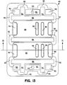
- FIG. 1 An important feature of the bottle shipping package half IPC structure 10 shown in Figs. 1-4 is the construction and arrangement of the cross ribs including end ribs 15, interior ribs 16, rows 20 of pods 22, and podded ribs 26 for stacking of tiers of bottles in the shipping package.
- the podded ribs 26 at the lower half or lower mid section of a bottle cavity 12 of a first half IPC structure 10 are aligned with interior cross ribs 16 at the upper half or upper mid section of an adjacent cavity 12 of a second half IPC structure 11 rotated 180° for stacking.
- the depths of the podded ribs 26 and cross ribs 16 are selected for abutting each other and transmitting stacking and loading forces around the product containing cavities in the back to back stacking relationship.
- four sets of complementary aligned mating podded ribs 26 and interior cross ribs or mid ribs 16 form four stacking support rows extending completely across the back to back IPC structures 10,11.
- the four stacking support rows are substantially evenly distributed along the length of the interior of the back to back IPC structures 10,11.
- podded ribs 26 abut against interior ribs 16 and vice versa.
- two partial stacking support rows are formed at the respective ends of the back to back IPC structures 10,11 formed by the abutting faces of end ribs 15 and end rows 20 of pods 22.
- the end ribs 15 are formed with sufficient depth to constitute stacking ribs abutting against the pods 22 of the rows 20 of the back to back abutting IPC structure 11.
- a total of six stacking support rows of abutting or mating podded ribs 26, mid portion cross ribs 16, end rows 20 of pods 22 and end ribs 15 provide ample support for the stacking and loading forces of multiple tiers of bottles, directing the stacking and loading forces to the base of the bottle shipping package.
- the design requirement for the bottle shipping package IPC structure was selected so that the package could withstand impact shock acceleration of 67 g's or greater from edge drops, corner drops, face drops, and horizontal impacts without transmitting more than 67 g's to the product and without wine bottle damage or breakage.
- This is accomplished by deployment of the foregoing crushable structures in the geometrical shapes and configurations distributed about the cavities as illustrated in Figs. 1-4.
- ASTM and NSTA Test Procedure Project 1A it has been determined that this deployment of crushable structures affords a predictable and reliable crushability and cushioning absorption of energy to prevent product damage by mechanical shock accelerations imparted to a package which approach or exceed the design limits of 67 g's.
- the molded fiber shell of the IPC structure is formed with a caliper of 0.15 cm (0.060 inches).
- the pods of each of the row of pods and the rib pods of each of the podded ribs are formed approximately 0.3 cm (0.125 inches) apart at the valleys or closest points of approach of adjacent pods. This in turn results in the formation of fillets between the pods of the rows of pods and the rib pods of the podded ribs forming an additional caliper thickness at the fillet locations of approximately 125 thousandths of an inch 0.3cm (0.125 inches).
- the fillets adjust the crushability of the crushable structures to the desired range for achieving the design requirements of the package and IPC structures.
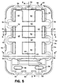
- the IPC structure 45 is the lower tray or lower end cap of a camera receiving IPC structure for a camera shipping package.
- the tray 45 is formed with intersecting lateral ribs 46 and longitudinal ribs 48 leaving plateaus 50 and shelves 52,53 which define the camera cavity wall along with a projecting end rib 54 projecting from shelf 53.
- the lateral ribs 46 at respective ends intersect with vertical ribs 55 which extend in a third orthogonal direction or axis relative to the lateral ribs 46 and longitudinal ribs 48.
- the longitudinal ribs 48 also terminate at one end in vertical ribs 56 extending in the third orthogonal direction.
- the tray therefore incorporates three dimensional ribs 46,48,55,56 providing intersecting and interlocking reinforcement along the three orthogonal axes which form an effective crushable "rib cage".
- the end of the tray 45 opposite the vertical ribs 56 which intersect with longitudinal ribs 48 is formed with a pair of shallow pods 58 which in turn intersect with vertical ribs 60 at the end of the tray opposite vertical ribs 56.
- the pods 58 and ribs 60 form an end of the tray extending beyond the projecting rib 54.
- the overall effect of the example of Figs. 5-9 is to provide an IPC structure shallow tray or end cap with crushable reinforcing ribs and structures intersecting in three dimensions around the cavity for surrounding and protecting the product or a contacting end of the product.
- the three dimensional ribs provide product protection from impact shock and transport mode vibrations and direct stacking and loading forces around the product containing cavity.
- the perimeter 62 of the tray or end cap 45 is also formed with scallops 64. The scalloped edge perimeter 62 strengthens the edges and provides further protection from lateral forces impacting the product containing IPC structure.
- a nesting configuration of multiple trays 45 is illustrated in Figure 9.
- the tapered configuration of the respective ribs permits nesting of trays facing in the same direction for efficient use of space in shipping empty trays.
- the projecting rib 54 also performs an anti-locking or denesting function preventing the nested trays 45 from locking together and making it difficult to separate the trays.
- the camera tray IPC structure was constructed to provide product protection from mechanical shock or vibration acceleration of 80 g's or greater imparted to the package.
- this design limit or threshold it was determined that the flash element of the camera would be released, pop up, and be exposed to potential damage and breakage. Protection of this sensitive element was achieved by deploying the crushable structure geometrical shapes and configurations around the product containing cavity as illustrated in Figs. 5-9. This construction provides the requisite crushability and cushioning energy absorption at mechanical shock accelerations from edge drops, corner drops, and face drops approaching the design requirement limit or threshold limit of 80 g's.
- the camera tray IPC structure shell was vacuum molded with a shell caliper of 0.15cm (0,060 inches).
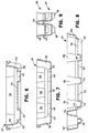
- FIG. 10-13 A laser printer toner cartridge end cap IPC structure 70 for a toner cartridge shipping package is illustrated in Figs. 10-13.
- the end cap IPC structure 70 is formed with a cavity 72 of unusual configuration conforming to the unusual or irregular shape at the end of the toner cartridge.
- the deep cavity 72 is formed with various shelves 74a,74b to accommodate and support the irregular three dimensional shape.
- the base of the cavity is also formed around its perimeter with a variety of pods 75 which support the cavity and provide product protection from impact shocks and transport mode vibrations.
- the pods 75 also have portions extending the full depth of the cavity 72 so that the pods 75 form posts 80,81.
- the post like function of the pods 75 supports and directs stacking and loading forces around the cavity in the case of vertical orientation in the shipping package. For lateral or horizontal orientation the pods 75 provide product protection from horizontal impact shock and vibrations.
- the perimeter 76 at the top of the end cap IPC structure may also be formed with a recess or scallop at necessary locations to increase edge strength and product protection.
- the pods 75 are arranged as double pods 75a,75b of a single post 80.
- the advantage of this configuration is that fillets 82 of molded pulp fiber material may be deposited in the valley between the outsides of the double pods 75a and 75b to reinforce the post for adjusting the crushability of the posts and bearing greater crushing forces and lateral forces.
- the double pod post also reinforces the capacity of the posts 80 for directing stacking and loading forces.
- the end cap IPC structure is formed with double podded post 81 with relatively large area pods 77a and 77b at the fourth corner of the IPC structure.
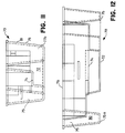
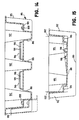
- FIG. 13-15 An interior package cushion structure for receiving and cushioning speakers in a speaker shipping package is illustrated in Figs. 13-15.
- the speaker receiving IPC structure 85 is formed with major lateral ribs 86 which define plateaus 88 between the ribs 86 and shelves 90 that form portions of the cavity wall for receiving the speaker.
- the lateral ribs 86 intersect at respective ends with vertical ribs 92 which extend at right angles to the lateral ribs 86.
- the lateral ribs 86 at the respective ends of the cavity also merge with orthogonal rib sections 94 which extend in a third orthogonal direction.
- the ribs 86,92,94, and 95 provide three dimensional rib reinforcement effectively forming a crushable "rib cage" around the cavity structure.
- the orthogonal rib sections 94 intersect with additional vertical ribs 95 at the ends of the IPC structure. Additional shelves 96 and narrow ribs 98 may be formed in the plateaus 88 providing additional relief in the cavity walls to strengthen the cavity walls, provide product protection, and accommodate any irregular shapes in the speaker to be fitted in the cavity.
- a nesting configuration of successive speaker receiving IPC structures facing in the same direction is illustrated in ghosted outline at the left side of Figure 14.
- Denesting lugs 100 may be added to shelves 90 to prevent locking engagement of nested structures.
- the cavity ribs 98 may similarly perform a denesting function.
- the primary function of the cavity ribs 98 is in supporting a product 102 seated in the cavity on the cavity wall plateaus 88 as illustrated in Figure 15.
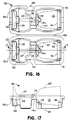
- FIG. 16-17 An IPC structure 105 for shipping wine glasses in a wine glass shipping package is illustrated in Figs. 16-17.
- the wine glass shipping IPC structure consists of two mirror image half IPC structures 105a and 105b hinged together by an integrally molded, molded pulp fiber hinge 106 for enclosing a wine glass 107 in the IPC structure 105.
- a tab 108 is provided to secure the wine glass receiving IPC structure in closed position through the tab receiving opening 110.
- the major features of the wine glass shipping IPC structure include a wine glass globe receiving and enclosing cavity 112 formed with a shelf 114 which engages the rim of the globe to offset the globe from the side wall 112 of the cavity.
- the cavity 112 is also formed with subsidiary shelves 115 at the upper corners.
- the stem supporting bridging rib 116 which crosses the halves 105a and 105b at approximately the center of the IPC structure.
- the bridging ribs 116 which cross the half IPC structures are formed with appropriate recesses 116a to accommodate the stem of the wine glass. While the bridging rib 116 is a horizontal rib, it is supported or reinforced by selected vertical ribs 118 extending from the side of the bridge rib 116 into the cavity 112.
- each half IPC structure 105a,105b there is formed a bridge rib 120 extending across the half IPC structure adjacent to a recessed rib 122 for receiving and accommodating the base of the wine glass.
- the combination of structural shapes in the wine glass shipping IPC structure 105 including the cavity shelves 114,115, stem bridging rib 116, base support bridging rib 120 and recess rib 122 provide distributed product protection, absorbing impact shocks and vibrations and distributing impact shocks and vibrations that are transmitted, to the regions of the wine glass structure best able to withstand them.
- the wine glass shipping IPC structure was designed to achieve product protection approaching a design limit or threshold of 60 g's shock acceleration from a 1,5 m (five foot) drop.
- the deployment of crushable structured geometric shapes and configurations as illustrated in Figs. 16 and 17 with a molded pulp fiber shell caliper of 0.15cm (0,060 inches) achieve the required crushability and cushioning absorption of energy for predictable and reliable product protection at the design limit threshold.
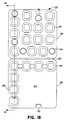
- a corner protector IPC structure 125 is illustrated in Figures 18-21.
- the corner protector 125 is formed with an outer base 126 and an inner base 128 joined together at a flexible molded pulp fiber hinge 130.
- the corner protector 125 is shown in open position in Figs. 18 and 19 for stacking as shown in Fig. 21.
- the outer and inner bases 126, 128 are joined together by the complementary tab 132 and tab notch 134.
- the corner protector 125 is formed with an array of pods 135, 136 in the outer base 126 and pods 138 in the inner base 128.
- the corner protector 125 with its outer and inner bases 126,128 and array of pods 135,136,138 is essentially constructed in a corner cube configuration for seating at the corners of a package and defining a corner cube space 140 for fitting over the corner of a product or a corner of a stack of IPC structures to be shipped in the package.
- the corner protectors are constructed to support a product or a stack of products contained in IPC structures, spacing the contents from the corners of the package. Corner protectors may be inserted at all corners of the package.
- the array of structural pods projecting from the base 126 of the corner protector 125 incorporates a first set of pods 135 molded with a first selected depth, and a second set of pods 136 molded with a second selected depth less than the first.
- the array of pods 135,136 may project from one side of the base 126.
- the first set of pods 135 presents a first level of crushability with a lesser resistance to crushing from corner drop, edge drop, and face drop impacts for absorbing impact shock and transport vibrations.
- the second set of pods present a second level of crushability with a greater resistance to further crushing.
- the configuration of the corner protector 125 therefore provides two different sequential levels of resistance to crushing by mechanical shock, vibrations, and stacking and loading forces.
- the corner protector 125 may be further reinforced by depositing fillets 142 of fiber material in the valleys between the outsides of pods 135,136 in the array.
- the fillets 142 substantially increase resistance to hinging or bending at the valleys between pods and resistance to lateral and longitudinal crushing.
- the fillets or gussets 142 effectively add a third level of crushability with even greater resistance to further crushing from mechanical impacts for absorbing impact shock and transport vibrations with higher levels of shock acceleration.
- the fillets buildup the thickness of molded fiber material at the valleys between pods to approximately 0.9cm (0.375 inch) to provide this third level of crushability.
- the larger pods 138 formed on the inner base 128 of corner protector 125 add yet another controllable parameter for crushability and cushioning absorption of energy.
- the larger pods 138 face the product or stack of IPC structures and may be constructed, for example, to afford the greatest crushing compliance and least resistance to crushing for product protection. It is apparent, in any event, that the array of different size pods of the corner protector of Figs. 18-21 affords multiple levels of crushability and absorption of energy for multiple impacts or successive impacts at different shock accelerations for meeting the requirements of different design limits and thresholds.
- the array of pods 135,136,138 and fillets 142 formed on the bases 126,128 of corner protector 125 may also be molded directly into molded pulp fiber IPC structures for shipping relatively heavy but delicate and sensitive equipment such as television sets and other electronic equipment.
- the array of pods as illustrated in Figs. 18 and 19 is formed at locations distributed around a product receiving cavity for relatively heavy products and equipment with relatively delicate sensitive elements.
- the array of pods 135,136,138 and fillets 142 design into the IPC structure multiple levels of crushability affording multiple levels of product protection.
- the multilevel pod array is constructed to provide the requisite crushability and cushioning absorption of energy for product protection at multiple design limits and thresholds for shock acceleration at which damage or breakage to sensitive elements may occur. As impact shock accelerations approach the respective design limits and thresholds, successive crushing and absorption of energy reduces transmission of shock accelerations to the product within acceptable limits.
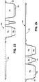
- a large cosmetic kit tray IPC structure 150 is illustrated in Fig. 22 showing the use of friction fit pockets and crush ribs.
- the large cosmetic kit tray includes a base 152 formed with friction fit pockets 154 for receiving and containing bottles, jars, and other containers of cosmetic materials.
- the crush fit cavities 154 are formed with crush ribs 155 as hereafter described.
- the large cosmetic kit tray 150 is formed with a cover 156 hingedly connected to the base 152 by a flexible molded pulp fiber hinge 158.
- each of the product receiving friction fit cavities 154 is formed with a plurality of crush ribs 155 protruding into the cavity or pocket 154.
- the juxtaposed crush ribs 155 define a pocket width less than the width dimension of a product to be inserted and contained in the pocket 154.
- the forcible insertion may have two effects. The primary effect is to cause breaking, tearing, or parting of fibers in the respective crush ribs 155.
- the crush ribs are permanently deformed in the process of forcible insertions. Second, the forcible insertion also causes some widening of the pocket 154 itself stressing pocket fibers and perhaps in some instances causing some breaking or parting of the pocket fibers.
- ribs 158 are provided at the ends of one of the elongate crush fit pockets 154 to provide further product protection.
- the cover 156 on hinge 158 is secured in place by tabs 160 which engage tab notches 162.
- the cavities 154 are formed with pods 164 for supporting the tray on a base and for stacking trays on each other with pods of one tray resting on the cover of another tray.
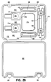
- a small cosmetic tray IPC structure 170 is illustrated in Fig. 28 showing the use of a suspended pocket structure.
- the small cosmetic kit tray 170 is formed with a base 172 in which are molded various pockets for receiving cosmetic containers.
- the base 172 is formed with pockets 174 for receiving nail polish bottles, pockets 175 for retaining lipstick containers, pockets 176 for eye brow pencils, and a suspended pocket 178 for containing an eye shadow beauty compact.
- the tray 170 is also formed with a cover 180 flexibly hinged to the base 172 by a molded pulp fiber hinge 182. The cover can be secured over the base 172 by securing tabs 184 in tab notches 185.
- the suspended pocket 178 for receiving the eye shadow compact is distinguished from pockets and cavities previously described in other examples in that the suspended pocket 178 is formed with no other contiguous structures or shapes including ribs, pods, or shaped cavity elements.
- the suspended pocket 178 is suspended between the other pockets 174,175,176 which effectively form suspension ribs for suspension pocket 178.
- a further distinguishing feature is that no part of the product, in this case the eye shadow compact, and no part of the suspended pocket 178 touches an external package or any other IPC structure during shipping, distribution, and handling.
- pods 186 formed in the nail polish pockets 174 elongate pods or rib pods 188 formed in the lipstick pockets 175, and pods 190 formed in the eye brow pencil pockets 176.
- the pods 186,188, and 190 provide supports for the tray 170 and also function as stacking pods for stacking the trays 170 in closed position one on top of another.
- the stacking pods 186,188 and 190 rest on the cover 180 of the tray below.
- the cover 180 is in turn supported by ribs 192 left in the molded fiber shell of the tray between adjacent pockets 174,175,176 and 178.
- the raised lands or ribs 192 between pockets effectively form the stacking ribs mating with stacking pods 186,188,190 through the tray cover 180.
- These stacking features of the small compact kit tray 170 of Figs. 28 - 30 are also true of the large cosmetic kit tray 150 of Figs. 22-27.
- the pockets 174,175,176 and 178 of the small cosmetic tray 170 may be formed as crush fit pockets or friction fit pockets with crush ribs in the manner similar to crush ribs 155 of the large cosmetic kit tray 150.
- the stacking configuration for multiple small cosmetic kit trays 170 in open position is illustrated in Fig. 30.
- testing procedures and testing criteria for establishing the design requirements for molded pulp fiber IPC structures according to the invention are described in the article "ASTM and NSTA: Testing Criteria We Can Live With” The LAB INNOVATOR, Volume 2. No. 2, June, 1992 Published by LAB, 1326 New Skaneateles Turnpike, Skaneateles, New York 13152-8801. This article provides a general description of ASTM and NSTA test procedures and requirements.
- the test procedures of the National Safe Transit Association are set forth in "Test Procedure Project 1A" Published by the National Safe Transit Association, P.O. Box 10744, Chicago, Illinois 60610-0744.
Landscapes
- Engineering & Computer Science (AREA)
- Mechanical Engineering (AREA)
- Buffer Packaging (AREA)
- Packaging Frangible Articles (AREA)
Claims (37)
- Dämpfungsstruktur einer Innenverpackung aus geformter Zellstoffaser (IPC) zum Schutz eines in einer Verpackung beförderten Produktes mitwenigstens einem Hohlraum (12), der eine Hohlraumoberfläche (32) definiert, die ein zu beförderndes Produkt aufnimmt und hält, undmehreren verformbaren Hohlstrukturen mit mehreren Hohlkörpern (22, 28), die miteinander verbundene Seiten und einen Boden aufweisen und um den Hohlraum (12) der IPC-Struktur mit den Böden angeordnet sind, wobei zumindest einige der verformbaren Strukturen von der Hohlraumoberfläche (32) beabstandet sind, wobei jede verformbare Struktur sich zu verformen beginnt, wenn sie einer Kraft größer einer vorbestimmten Kraft ausgesetzt wird, wobei die vorbestimmte Kraft die experimentell bestimmte minimale Kraft ist, die für den Bruch des Produktes ausreicht,
gekennzeichnet durch
Verbindungsstücke (30) aus geformter Zellstoffaser zwischen benachbarten Hohlkörpern (22, 28) zur Anpassung ihrer Verformbarkeit. - IPC-Struktur nach Anspruch 1, wobei die strukturierten Hohlkörper (22) in Form von Vertiefungen oder Schächten vorgesehen sind und im wesentlichen im Querschnitt symmetrisch zu einer Mittelachse sind und an ausgewählten Orten mit ausgewählten Tiefen in der IPC-Struktur (10) ausgeformt sind.
- IPC-Struktur nach Anspruch 2, wobei die strukturierten Hohlkörper (22) wenigstens eine Reihe (20) von Hohlkörpern mit wenigstens drei nebeneinanderliegenden Hohlkörpern (22) mit geringem Abstand in linearer Abfolge aufweisen, die außerhalb der Reihe (20) der Hohlkörper (22) zwischen den Hohlkörpern der Reihe Einschnitte bilden.
- IPC-Struktur nach Anspruch 3, wobei die Verbindungsstücke (30) zwischen benachbarten Hohlkörpern außerhalb der Reihe (20) der Hohlkörper (22) in den Einschnitten angeordnet sind und in den Einschnitten eine Schicht geformter Zellstoffaser bilden, die dicker als die Schicht geformter Zellstoffaser der benachbarten Hohlkörper (22) ist, wobei die Verbindungsstücke (30) einen Teil der Einschnitte zwischen benachbarten Hohlkörpern auffüllen und die Hohlkörper teilweise miteinander verbinden.
- IPC-Struktur nach Anspruch 3, wobei die Reihe der in der IPC-Struktur (10) geformten Hohlkörper als Rippe ausgebildet ist und gerippte Hohlkörper (28) bildet, wobei die gerippten Hohlkörper (28) vollständig die Rippe (26) bilden und in linearer Abfolge in Richtung der Rippe (26) angeordnet sind, wobei die Rippe (26) und die gerippten Hohlkörper (28) eine gemeinsame Wand haben und eine gesamte hohlkörperartige Rippenstruktur bilden.
- IPC-Struktur nach Anspruch 4, wobei die Hohlkörper (22, 28) von einer größeren Querschnittsfläche bei der Öffnung der Vertiefung oder des Schachtes des Hohlkörpers (22, 28) zu einer geringeren Querschnittsfläche am Boden der Vertiefung oder des Schachtes konisch zulaufen, wobei die Verjüngung im wesentlichen symmetrisch um eine Mittelachse des Hohlkörpers (22, 28) ist.
- IPC-Struktur nach Anspruch 1 mit weiterhin ineinandergreifenden Rippen (54) und in der IPC-Struktur (10) geformten Hohlkörpern, damit mehrere in die gleiche Richtung schauende IPC-Strukturen (10) ineinandergreifen und somit den Platzbedarf für die Beförderung der IPC-Strukturen (10) minimieren, wenn keine Produkte in den jeweiligen Hohlräumen (12) vorliegen, wobei die strukturierten Rippen, Hohlkörper und Hohlräume (12) jeweils an die Vertiefungen angepaßt sind, die für ein effizientes Ineinandergreifen in die gleiche Tiefenrichtung ausgebildet sind.
- IPC-Struktur nach Anspruch 7, die weiterhin dem Ineinandergreifen entgegenwirkende Sitze (100) aufweist, die in der IPC-Struktur (10) ausgebildet sind und ein sperrendes Ineinandergreifen der ineinandergreifenden IPC-Strukturen (10) verhindern.
- IPC-Struktur nach Anspruch 7, wobei die Verbindungsstücke (30) eine dem Ineinandergreifen entgegenwirkende Funktion ausüben, um ein Sperren der ineinandergreifenden IPC-Strukturen (10) zu verhindern.
- IPC-Struktur nach Anspruch 1, wobei die verformbaren Strukturen sich schneidende Rippen aufweisen, die sich in wenigstens drei senkrechte Längsrichtungen erstrecken und ein dreidimensionales verformbares Rippengerüst bilden, das sich um wenigstens einen Teil des Produktes im Hohlraum (12) erstreckt.
- IPC-Struktur nach Anspruch 1, die weiterhin Stapelrippen und Hohlkörper aufweist, die um die Hohlräume (12) verteilt und entfernt von ihnen angeordnet sind, wobei die Stapelrippen und Hohlkörper so angeordnet sind, daß die Stapelrippen und Hohlkörper von benachbarten IPC-Strukturen (10) jeweils Rücken an Rücken aneinandergefügt sind, wobei die Stapelrippen und Hohlkörper außerhalb einer IPC-Struktur auf den Stapelrippen und Hohlkörpern einer weiteren IPC-Struktur (10) liegen, die zum Stapeln von in den Hohlräumen (12) gehaltenen Produkten verwendet wird, wobei die aneinandergefügten Stapelrippen und Hohlkörper so angeordnet sind, daß sie die Stapel- und Belastungskräfte über die aneinandergefügten Stapelrippen und Hohlkörper um die Hohlräume (12) zum Grund einer Verpackung übertragen, wobei die aneinandergefügten Stapelrippen und Hohlkörper unterschiedliche Höhen aufweisen, womit eine seitliche Bewegung nahe zueinander angeordneter, gestapelter IPC-Strukturen (10) verhindert wird.
- IPC-Struktur nach Anspruch 1, wobei die verformbaren Strukturen mehrere hohlkörperartige Rippen (26) aufweisen, wobei jede hohlkörperartige Rippe (26) aus einer Reihe von Hohlkörpern von wenigstens drei strukturierten gerippten Hohlkörpern (28) in Form von hohlen Schächten oder Vertiefungen gebildet ist, die jeweils im wesentlichen im Querschnitt symmetrisch zu einer Mittelachse sind, wobei die Reihe der gerippten Hohlkörper (28) vollständig in der hohlkörperartigen Rippe enthalten ist, wobei die hohlkörperartige Rippe (26) und die Reihe von gerippten Hohlkörpern (28) gemeinsame Wände haben und eine gesamte hohlkörperartige Rippenstruktur bilden, wobei die gerippten Hohlkörper (28) mit einer ausgewählten Tiefe ausgebildet sind, die geringer ist, als die gesamte Tiefe der hohlkörperartigen Rippe (26) in der IPC-Struktur (10), wobei die gerippten Hohlkörper nahe zueinander in linearer Abfolge und in gleicher Richtung mit der hohlkörperartigen Rippe (26) vorgesehen sind, wodurch außerhalb der hohlkörperartigen Rippe (26) Einschnitte zwischen den gerippten Hohlkörpern (28) der Reihe gebildet werden, wobei die gerippten Hohlkörper (28) einen zusätzlichen Schutz für das Produkt im Hohlraum (12) gegenüber einem mechanischen Stoß und Schwingungsbeschleunigungen und Stapel- und Belastungskräften liefern, wobei die gerippten Hohlkörper (28) so ausgebildet sind, daß sich die Verformbarkeit der hohlkörperartigen Rippe (26) mit zunehmendem Widerstand gegenüber der Verformung der hohlkörperartigen Rippe (26) anpaßt.
- IPC-Struktur nach Anspruch 1, wobei die verformbaren Strukturen strukturierte Rippen in Form von länglichen Hohlleisten aufweisen, die in der IPC-Struktur (10) geformt sind.
- IPC-Struktur nach Anspruch 1, die weiterhin eine Kante mit periodischen bogenförmigen Ausschnitten (64) oder Einschnitten aufweist, um der Kante einen verstärkten Widerstand gegenüber Verformung zu verleihen und um Stoßkräfte bei der Kante der IPC-Struktur (10) zu übertragen und zu absorbieren.
- IPC-Struktur nach Anspruch 1, die weiterhin wenigstens einen Absatz (53) mit einer Stufenstruktur aufweist, der zwischen einer Höhe der IPC-Struktur (10) und einer weiteren Höhe ausgebildet ist, um ein Produkt im Hohlraum 12 zu halten, den Hohlraum (12) zu verstärken und den Produktschutz zu erhöhen.
- IPC-Struktur nach Anspruch 2, die weiterhin mehrere strukturierte Rippen aufweist, die sich in drei zueinander senkrechten Richtungen oder Achsen erstrecken, wobei sich die Rippen schneiden und somit eine verstärkte dreidimensionale verformbare Rippenkäfigstruktur bilden.
- IPC-Struktur nach Anspruch 1, wobei der Hohlraum einen Hohlraum mit Reibpassung aufweist, der mit Quetschrippen (155) gebildet ist, die in den Hohlraum hineinragen, wobei die Quetschrippen (155) zumindest die Breite des Hohlraums definieren, die geringer ist, als die entsprechende Breite eines in dem Hohlraum enthaltenen Produktes, wobei der Hohlraum mit Reibpassung und Quetschrippen (155) so ausgebildet ist, daß die Fasern der Quetschrippen (155) verformt werden, wenn ein Produkt in den Hohlraum mit Reibpassung eingeführt wird, so daß ein Hohlraum mit Reibpassung und mit elastischer Schwingungsdämpfung und mit einer kombinierten Struktur aus Quetschrippen (155) gebildet wird.
- IPC-Struktur nach Anspruch 1, wobei der Hohlraum ein hängendes Fach (178) aufweist, das zwischen den länglichen Halterippen aufgehängt ist, wobei das hängende Fach (178) und die Halterippen so ausgebildet sind, daß sie ein Produkt in Halteposition so im hängenden Fach (178) halten und tragen, daß kein Teil des Produktes oder des hängenden Faches (178) die Außenverpackung oder weitere IPC-Strukturen (170) während der Beförderung oder des Transports berührt.
- IPC-Struktur nach einem der Ansprüche 1 bis 18 zur Beförderung mehrerer Flaschen in einer Verpackung, wobei jede IPC-Struktur (10), die einen Hohlraum (12) definiert, eine Hohlraumoberfläche (32) zur Aufnahme und Halterung einer Flasche definiert, wobei die Hohlraumoberfläche (32) gebogene Rippen aufweist, die die Stärke der IPC-Struktur (10) verstärken, wobei die IPC-Struktur (10) und die Verbindungsteile (30) aus einer Dicke geformter Zellstoffaser gebildet sind, und wobei die verformbaren Strukturen Kräfte und Beschleunigungen bei einer gewählten Grenzbeschleunigung, der die Flaschen ausgesetzt wurden, von 67 g bis ungefähr 114 g auf weniger als ungefähr 67 g verringern, wobei die IPC-Struktur weiterhin Stapelrippen und Hohlkörper aufweist, um mehrere Lagen von Flaschen übereinander zu stapeln, die in mehreren IPC-Strukturen gehalten werden.
- IPC-Struktur nach Anspruch 19, wobei die Dicke der geformten Zellstoffaser der IPC-Struktur ungefähr 0,15 cm und wobei die Dicke der geformten Zellstoffaser der Verbindungsteile ungefähr 0,3 cm ist.
- IPC-Struktur nach einem der Ansprüche 1 bis 20, wobei eine Spalte Hohlkörper einen ersten Satz Hohlkörper aufweist, der mit einer ersten ausgewählten Tiefe geformt ist, und einen zweiten Satz Hohlkörper (136), der mit einer zweiten ausgewählten Tiefe geformt ist, die geringer als die erste gewählte Tiefe ist, wobei die Reihe der Hohlkörper ein geringeres Beschleunigungs- und Verbiegungsniveau und einen geringeren Widerstand gegenüber Verformung durch den ersten Satz Hohlkörper (135) gewährleistet und ein höheres Beschleunigungs- und Verbiegungsniveau und einen höheren Widerstand gegenüber Verbiegung gewährleistet, nachdem die Hohlkörper (135) des ersten Satzes bis zur Tiefe des zweiten Hohlkörpersatzes (136) verformt wurden, womit die Reihe des ersten und zweiten Hohlkörpersatzes (135, 136) zwei unterschiedliche aufeinanderfolgende Verformbarkeits- und Widerstandsniveaus gegenüber der Verformung haben.
- IPC-Struktur nach Anspruch 21, wobei der Satz Hohlkörper (135, 136) aus Verbindungsstücken (142) von geformter Zellstoffaser gebildet ist, die in den Einschnitten zwischen den Außenseiten von nahe zueinander angeordneten Hohlkörpern liegen und somit ein drittes Beschleunigungs- und Verformbarkeitsniveau mit größerem Verformungs- und Verbiegungs- oder Verdrehungswiderstand bei den Einschnitten zwischen den Hohlkörpern (135, 136) liefert.
- IPC-Struktur nach einem der Ansprüche 1 bis 22, wobei die strukturierten Rippen Antiverkippungsrippen aufweisen, die einer Verkippungsbewegung oder Biegebewegung der IPC-Struktur entgegenwirken.
- Verfahren zur Herstellung einer Dämpfungsstruktur einer Innenverpackung (IPC) zum Schutz eines in einer Verpackung beförderten Produktes, wobei ein geformtes Zellstoffaserstück und wenigstens ein Hohlraum (12) vorgesehen ist, der eine Hohlraumoberfläche (32) definiert, die ein Produkt auf dem geformten Zellstoffaserstück aufnimmt und hält, mit folgenden Verbesserungen:experimenteller Bestimmung einer minimalen Kraft, die ausreicht, ein in einer Verpackung zu beförderndes Produkt zu brechen, wobei das Produkt zerbrechliche Komponenten aufweist, undBildung mehrerer verformbarer Hohlstrukturen mit mehreren Hohlkörpern (22, 28), die miteinander verbundene Seiten mit einem Boden um den Hohlraum (12) aufweisen, wobei die Böden der verformbaren Strukturen von der Hohlraumoberfläche (32) beabstandet sind, wobei jede verformbare Struktur groß genug ist, daß die Struktur beginnen kann, sich zu verformen, wenn sie einer Kraft ausgesetzt ist, die gleich oder größer der minimalen Kraft ist, und wobei Verbindungsstücke aus geformter Zellstoffaser zwischen benachbarten Hohlkörpern (22, 28) angeordnet sind, um deren Verformbarkeit anzupassen.
- Verfahren nach Anspruch 24, wobei die Bildung mehrerer verformbarer Strukturen aufweist:Bildung mehrerer strukturierter Hohlkörper in Form von hohlen Vertiefungen oder Schächten, die im wesentlichen im Querschnitt symmetrisch zu einer Mittelachse sind und mit ausgewählten Tiefen in der IPC-Struktur (10) bei ausgewählten Orten ausgebildet sind.
- Verfahren nach Anspruch 25, wobei die Bildung mehrerer strukturierter Hohlkörper die Bildung von wenigstens einer Reihe von Hohlkörpern aufweist, die wenigstens drei Hohlkörper aufweist, die nahe zueinander in linearer Abfolge angeordnet sind, wodurch sich zwischen benachbarten Hohlkörpern der Reihe außerhalb der Reihe der Hohlkörper Einschnitte bilden.
- Verfahren nach Anspruch 24 und 26, dadurch gekennzeichnet, daß die Verbindungsteile (30) aus geformter Zellstoffaser in den Einschnitten zwischen benachbarten Hohlkörpern (22) außerhalb der Reihe (20) der Hohlkörper (22) angeordnet sind und eine Schicht geformter Zellstoffaser in den Einschnitten bilden, die dicker ist als die Schicht benachbarter Hohlkörper (22), wodurch ein Teil der Einschnitte zwischen benachbarten Hohlkörpern gefüllt wird, wodurch die Hohlkörper (22) teilweise aneinandergefügt werden, und die Verformbarkeit der Reihe (20) der Hohlkörper (22) angepaßt wird, indem die Verbindungsstücke (30) eine ausgewählte Dicke f haben, oder indem der Verformungs-, Verdrehungs- oder Verkippungswiderstand bei den Einschnitten zwischen den Hohlkörpern vergrößert wird.
- Verfahren nach Anspruch 24, dadurch gekennzeichnet, daß die Reihe der in der IPC-Struktur (10) geformten Hohlkörper eine Rippe bildet, wobei die Reihe der Hohlkörper vollständig in der Rippe enthalten ist und die Hohlkörper der Reihe in gleicher Richtung entlang der Rippe angeordnet sind und die Rippe und die Reihe der Hohlkörper eine gesamte hohlkörperartige Rippenstruktur mit gemeinsamen Wänden bilden.
- Verfahren nach Anspruch 24, wobei die Hohlkörper (22, 24) sich von einer größeren Querschnittsfläche bei der Öffnung der Vertiefung oder des Schachtes der Hohlkörper (22, 24) zu einer geringeren Querschnittsfläche am Boden der Vertiefung oder des Schachtes verjüngen, wobei die Verjüngung im wesentlichen symmetrisch um eine Mittelachse ist, und wobei wenigstens ein Hohlraum (12), Rippen und in der IPC-Struktur geformte Hohlkörper mit jeweils geformten Vertiefungen angeordnet sind, die sich in die gleiche Richtung erstrecken, so daß mehrere in die gleiche Richtung ausgerichtete IPC-Strukturen (10) ineinandergreifen und somit die Platzbedürfnisse zur Beförderung der IPC-Strukturen (10) minimieren, wenn kein Produkt im Hohlraum vorliegt.
- Verfahren nach Anspruch 24, wobei die Bildung mehrerer verformbarer Strukturen die Bildung sich schneidender Rippen aufweist, die sich in wenigstens drei senkrechten Längsrichtungen erstrecken und einen verformbaren Rippenkäfig bilden, der sich um wenigstens einen Teil des Produktes in dem Hohlraum (12) erstreckt.
- Verfahren nach Anspruch 24, das weiterhin Stapelrippen und Hohlkörper aufweist, die angeordnet sind, daß die Stapelrippen und Hohlkörper von nahe zueinander angeordneten IPC-Strukturen (10) Rücken an Rücken zusammengefügt sind, wodurch Zusammenfügungs- oder Stirnflächenstapelrippen und Hohlkörper mit unterschiedlichen Höhen gebildet werden, die die seitliche Bewegung von nahe zueinander angeordneten IPC-Strukturen (10) in einem Stapel verhindern, wobei die Stapelrippen und Hohlkörper außerhalb einer IPC-Struktur (10) auf den Stapelrippen und Hohlkörpern außerhalb einer anderen IPC-Struktur (10) zum Stapeln von Produkten liegen, die in den Hohlräumen der IPC-Strukturen in der Verpackung liegen, und die Stapelkräfte und Belastungskräfte über die zusammengefügten Stapelrippen und Hohlkörper um die Hohlräume herum bis zum Boden des Pakets übertragen.
- Verfahren nach Anspruch 24, wobei eine Reihe Hohlkörper (135, 136) eine Reihe von nahe zueinander angeordneten Hohlkörpern ist, die in linearer Reihenfolge zueinander angeordnet sind.
- Verfahren nach Anspruch 24, wobei die Bildung mehrerer verformbarer Strukturen weiterhin die Bildung wenigstens einer Rippe aufweist, wobei die Reihe von Hohlkörpern wenigstens drei rippenförmige Hohlkörper aufweist, die nahe zueinander in linearer Abfolge in gleicher Richtung wie die Rippe angeordnet sind, wobei die rippenförmigen Hohlkörper im wesentlichen symmetrisch im Querschnitt zu einer Mittelachse sind und die rippenförmigen Hohlkörper mit ausgewählter Tiefe bilden, die geringer ist als die Tiefe der Rippe, die die Reihe der Hohlkörper in der Rippe enthält und die Rippe und die Reihe der Hohlkörper als eine gesamte hohlkörperartige Rippenstruktur mit gemeinsamen Wänden bildet.
- Verfahren nach Anspruch 24, das weiterhin die Bildung von Stapelrippen und Hohlkörpern aufweist, die angeordnet sind, daß die Stapelrippen und Hohlkörper von nahe zueinander angeordneten IPC-Strukturen (10) zusammengefügt werden können, wodurch zusammengefügte oder aneinanderstoßende Stapelrippen und Hohlkörper mit unterschiedlicher Länge gebildet werden, um eine seitliche Bewegung nahe zueinander angeordneter IPC-Strukturen (10) in einem Stapel zu verhindern, den Verbleib der Stapelrippen und Hohlkörper außerhalb einer IPC-Struktur (10) auf den Stapelrippen und Hohlkörper außerhalb einer anderen IPC-Struktur zum Stapeln von Produkten, die in den Hohlräumen in einer Verpackung liegen, und die Übertragung der Stapel- und Belastungskräfte über diese zusammengefügten Stapelrippen und Hohlkörper um die Hohlräume herum bis zum Boden des Pakets.
- Verfahren nach Anspruch 24, gekennzeichnet durch die Bildung der Strukturen, die die zu den Flaschen übertragenen Kräfte und Beschleunigungen oberhalb einer Grenzbeschleunigung von ungefähr 67 g bis zu wenigstens ungefähr 114 g auf weniger als ungefähr 67 g vermindert.
- Verfahren nach Anspruch 24, das weiterhin die Bildung der IPC-Struktur mit einer Dicke einer geformten Zellstoffaser von ungefähr 0,15 cm aufweist und die Bildung der Verbindungsstücke mit einer Dicke von ungefähr 0,3 cm.
- Verfahren nach Anspruch 24 und 28, das weiterhin die Bildung mehrerer strukturierter Rippen in Form von länglichen Hohlleisten aufweist, die in der IPC-Struktur (10) ausgebildet sind und sich zwischen den verschiedenen Orten auf der IPC-Struktur erstrecken, um die IPC-Struktur (10) zwischen den Orten zu verstärken.
Applications Claiming Priority (3)
| Application Number | Priority Date | Filing Date | Title |
|---|---|---|---|
| US07/927,061 US5335770A (en) | 1992-08-06 | 1992-08-06 | Molded pulp fiber interior package cushioning structures |
| US927061 | 1992-08-06 | ||
| PCT/US1993/007324 WO1994003377A1 (en) | 1992-08-06 | 1993-08-04 | Molded pulp fiber interior package cushioning structures |
Publications (3)
| Publication Number | Publication Date |
|---|---|
| EP0654001A1 EP0654001A1 (de) | 1995-05-24 |
| EP0654001A4 EP0654001A4 (de) | 1996-05-22 |
| EP0654001B1 true EP0654001B1 (de) | 1999-06-02 |
Family
ID=25454109
Family Applications (1)
| Application Number | Title | Priority Date | Filing Date |
|---|---|---|---|
| EP93918633A Expired - Lifetime EP0654001B1 (de) | 1992-08-06 | 1993-08-04 | Innenverpackung mit einer polsterstruktur aus geformter faserpulpe |
Country Status (7)
| Country | Link |
|---|---|
| US (2) | US5335770A (de) |
| EP (1) | EP0654001B1 (de) |
| JP (1) | JP3335175B2 (de) |
| AT (1) | ATE180733T1 (de) |
| CA (1) | CA2141784C (de) |
| DE (1) | DE69325175T2 (de) |
| WO (1) | WO1994003377A1 (de) |
Families Citing this family (78)
| Publication number | Priority date | Publication date | Assignee | Title |
|---|---|---|---|---|
| US5656135A (en) * | 1993-02-16 | 1997-08-12 | Moulded Fibre Technology, Inc. | Molded product manufacturing apparatus and methods |
| US5593030A (en) * | 1995-05-19 | 1997-01-14 | Tell; Richard B. | Compact disc holder |
| CA2177669C (en) * | 1995-06-06 | 2001-01-16 | Roy William Emery | Resilient cushion packaging |
| US5772037A (en) * | 1995-11-15 | 1998-06-30 | Hurley; Richard D. | Shipping protector |
| CA2198661A1 (en) * | 1996-02-27 | 1997-08-27 | Richard B. Hurley | Shipping protector for bottles or the like |
| USD395234S (en) | 1996-07-25 | 1998-06-16 | Sydek Kabushiki Kaisha | Safeguard case for toner cartridge |
| US6010007A (en) * | 1997-02-21 | 2000-01-04 | Plastofilm Industries, Inc. | Thermoformed fragility packaging |
| US5950829A (en) * | 1998-05-14 | 1999-09-14 | Gale; Gregory W. | Packaging including a shell for bottles |
| US6109444A (en) | 1998-12-21 | 2000-08-29 | Lucent Technologies Inc. | Multi-function packing insert |
| US6123200A (en) * | 1999-04-06 | 2000-09-26 | Plastofilm Industries | Fragility packaging article with controlled resiliency |
| US6290057B1 (en) | 1999-09-10 | 2001-09-18 | Western Pulp Products Co. | Bottle shipper |
| AUPQ427399A0 (en) * | 1999-11-26 | 1999-12-23 | Micor Packaging Pty Ltd | Cushioning material |
| NL1017689C2 (nl) * | 2001-03-26 | 2002-09-27 | Huhtamaki Protective Packaging | Verpakking uit gevormd papiervezelmateriaal. |
| US6629608B2 (en) * | 2001-08-22 | 2003-10-07 | Western Pulp Products Co. | Shipping protector |
| NZ531457A (en) * | 2001-09-04 | 2007-09-28 | Anne Brown Sculthorpe | A support for bottles where multiple supports interact to support the edges of the support |
| AU2002325083B2 (en) * | 2001-09-04 | 2008-05-22 | Anne Brown Sculthorpe | A support for bottles |
| US7237675B2 (en) * | 2002-04-09 | 2007-07-03 | O'malley Joseph | Bottle cradle stacking support |
| US7681733B2 (en) * | 2002-08-29 | 2010-03-23 | Colbert Packaging Corporation | Packaging container with criss-cross grain pattern having product holding chambers and method for making the same |
| US7032747B2 (en) * | 2002-12-02 | 2006-04-25 | Hni Technologies Inc. | Reusable packaging system |
| ES1056482Y (es) * | 2003-12-10 | 2004-07-16 | Calduch Pedro Vinals | Bandeja para el soporte y almacenamiento horizontal de botellas. |
| US20070138047A1 (en) * | 2004-01-26 | 2007-06-21 | Keyes Fibre Corporation | Tray for protective packaging |
| US7318526B2 (en) * | 2004-07-01 | 2008-01-15 | Western Pulp Products Company | Overhang edge shipping protector |
| US20060150581A1 (en) * | 2005-01-11 | 2006-07-13 | Assembly & Test Worldwide, Llc | Apparatus for manufacturing biodegradable food service article and method |
| US20070119122A1 (en) * | 2005-11-30 | 2007-05-31 | David Shepps | Environmentally sustainable packaging and method of making thereof |
| US20080083634A1 (en) * | 2006-10-05 | 2008-04-10 | Harold Parker | Method and device for holding objects |
| US7789239B2 (en) * | 2006-12-11 | 2010-09-07 | Don Juliano | Insert trays for packages, packages including such trays, and methods for packaging articles of manufacture |
| US9485917B2 (en) * | 2006-12-15 | 2016-11-08 | Ecovative Design, LLC | Method for producing grown materials and products made thereby |
| US20080257762A1 (en) * | 2007-04-20 | 2008-10-23 | Padmanabhan Mahalingam | Systems and Methods for Storing Beverage Containers During Transport Shipping and Warehousing |
| GB2441019A (en) * | 2007-05-08 | 2008-02-20 | Dominic Bryant | A packaging insert for securing items within a larger carton |
| ES2288444B1 (es) * | 2007-07-25 | 2008-09-16 | Freixenet, S.A. | Placa para soporte y almacenamiento de envases. |
| US8230997B1 (en) | 2007-11-02 | 2012-07-31 | Mcwilliams Glenn P | Bottle support for packaging and shipping |
| US7866478B2 (en) * | 2008-03-13 | 2011-01-11 | Apple Inc. | Packaging for an article |
| CA131049S (en) | 2009-06-12 | 2010-02-02 | Gourmet Settings Inc | Modular pulp package |
| US8701884B2 (en) * | 2009-06-24 | 2014-04-22 | Kevin Gregg Williams | Shipping container for bottles |
| US20110062040A1 (en) * | 2009-09-11 | 2011-03-17 | Rich Mark H | Edge protector |
| CN101863333A (zh) * | 2010-06-03 | 2010-10-20 | 李苏扬 | 一种盒装酒瓶托 |
| US8434620B2 (en) | 2010-08-10 | 2013-05-07 | Grafcor Packaging, Inc. | Bottle shipment packaging and method |
| US8317018B2 (en) | 2010-08-23 | 2012-11-27 | Marayna LLC | Cigar package |
| US8757384B2 (en) | 2010-11-03 | 2014-06-24 | Dell Products, Lp. | Devices and methods for packing |
| USD702125S1 (en) * | 2012-04-26 | 2014-04-08 | Joseph L. Marchetti | Optical drive cushion made from biodegradable, recycled paper pulp |
| USD702126S1 (en) * | 2012-05-04 | 2014-04-08 | Joseph L. Marchetti | Hard drive cushion made from biodegradable, recycled paper pulp |
| JP6112783B2 (ja) * | 2012-06-08 | 2017-04-12 | キヤノン株式会社 | 梱包体 |
| GB201220789D0 (en) * | 2012-11-19 | 2013-01-02 | Protective Packaging Systems Ltd | Packaging |
| US11277979B2 (en) | 2013-07-31 | 2022-03-22 | Ecovative Design Llc | Mycological biopolymers grown in void space tooling |
| US20150101509A1 (en) | 2013-10-14 | 2015-04-16 | Gavin R. McIntyre | Method of Manufacturing a Stiff Engineered Composite |
| US9914555B2 (en) | 2014-06-27 | 2018-03-13 | Apple Inc. | Packaging insert |
| US9738424B2 (en) | 2014-07-11 | 2017-08-22 | Apple Inc. | Molded fiber packaging |
| US10858138B2 (en) * | 2014-12-19 | 2020-12-08 | The Coca-Cola Company | Carbonated beverage bottle bases and methods of making the same |
| US10537070B2 (en) | 2015-04-15 | 2020-01-21 | Ecovative Design Llc | Process for the production of mycelial composite surfaces in a roll-to-roll format |
| CN109153964B (zh) | 2016-03-01 | 2023-06-13 | 芬德集团公司 | 丝状真菌生物垫、及其生产方法和使用方法 |
| ITUA20164812A1 (it) * | 2016-06-30 | 2017-12-30 | Pusterla 1880 S P A | Confezione per il contenimento e l’esposizione di prodotti o articoli di pregio e di lusso, quali profumi, creme, prodotti alcolici, cosmetica di alta gamma, accessori di alta moda, gioielli e/o simili. |
| US10124924B2 (en) | 2016-08-08 | 2018-11-13 | Acorn West LLC | Beverage container packaging |
| US20180079579A1 (en) * | 2016-09-19 | 2018-03-22 | Mianhong Chen | Combined molded pulp tray |
| USD833301S1 (en) * | 2017-01-27 | 2018-11-13 | Western Digital Technologies, Inc. | Nesting and shock absorbing package |
| US10654613B2 (en) | 2017-01-27 | 2020-05-19 | Western Digital Technologies, Inc. | Nesting and shock absorbing package |
| BR112019020132B1 (pt) | 2017-03-31 | 2023-12-05 | Ecovative Design, LLC | Material de biopolímero micológico processado e respectivo método de preparação |
| IT201700108243A1 (it) * | 2017-09-27 | 2019-03-27 | Tecnoform S R L | Confezione |
| US10507950B2 (en) | 2017-10-04 | 2019-12-17 | Berkley International, Llc | Shipping insert |
| US11266085B2 (en) | 2017-11-14 | 2022-03-08 | Ecovative Design Llc | Increased homogeneity of mycological biopolymer grown into void space |
| US11920126B2 (en) | 2018-03-28 | 2024-03-05 | Ecovative Design Llc | Bio-manufacturing process |
| US11293005B2 (en) | 2018-05-07 | 2022-04-05 | Ecovative Design Llc | Process for making mineralized mycelium scaffolding and product made thereby |
| JP2021523676A (ja) | 2018-05-24 | 2021-09-09 | エコベイティブ デザイン エルエルシー | 菌糸体生体材料を生成するプロセス及び装置 |
| US11359174B2 (en) | 2018-10-02 | 2022-06-14 | Ecovative Design Llc | Bioreactor paradigm for the production of secondary extra-particle hyphal matrices |
| US11070037B2 (en) | 2018-10-12 | 2021-07-20 | International Business Machines Corporation | Multi-directional impact protection with magnitude and direction indicator |
| US11261015B2 (en) | 2019-11-13 | 2022-03-01 | Acorn West LLC | Beverage container packaging |
| DE102019130853A1 (de) * | 2019-11-15 | 2021-05-20 | The Gillette Company Llc | Aufbewahrungs- und versandschale |
| US11685570B2 (en) | 2020-05-15 | 2023-06-27 | Acorn West LLC | Thermal regulating lay flat beverage container packaging |
| US11679908B2 (en) | 2020-08-14 | 2023-06-20 | International Paper Company | Tray with nesting anti-lock feature |
| USD956553S1 (en) | 2020-08-14 | 2022-07-05 | International Paper Company | Blank for punnet tray |
| USD957247S1 (en) | 2020-08-14 | 2022-07-12 | International Paper Company | Punnet tray |
| US11659677B2 (en) | 2020-09-21 | 2023-05-23 | Google Llc | Structural midframe for an electronic device having a camera and a speaker |
| WO2022087352A1 (en) | 2020-10-23 | 2022-04-28 | Tekni-Plex, Inc. | Multi-use bottle shipping assembly with resilient elements |
| WO2022144579A1 (en) | 2020-12-30 | 2022-07-07 | Universidade Do Minho | Injected polymeric packaging for a sensitive or fragile product and method thereof |
| US11265632B1 (en) | 2021-01-21 | 2022-03-01 | Google Llc | Speaker-integration system for an electronic device, and associated devices and systems |
| DE102021104978A1 (de) | 2021-03-02 | 2022-09-08 | Buhl-Paperform Gmbh | Verpackung für einen Gegenstand |
| AU2022270087A1 (en) | 2021-05-04 | 2023-12-07 | Ecovative Design Llc | Aerial mycelia and methods of making the same |
| DE102022134098A1 (de) * | 2022-12-20 | 2024-06-20 | Krones Aktiengesellschaft | Verfahren zum Herstellen eines Fasern umfassenden Behälters mit einer Fasern umfassenden Krempe, Fasern umfassender Behälter und Vorrichtung zum Ausführen des Verfahrens |
| US12104847B1 (en) * | 2023-04-28 | 2024-10-01 | Western Pulp Products Co. | Container shipping protector with improved thermal regulation |
Family Cites Families (68)
| Publication number | Priority date | Publication date | Assignee | Title |
|---|---|---|---|---|
| CA753853A (en) * | 1967-03-07 | F. Reifers Richard | Molded pulp egg carton | |
| CA680198A (en) * | 1964-02-18 | S. Wolf George | Packaging | |
| DK126369A (de) * | ||||
| CA793649A (en) * | 1968-09-03 | Keyes Fibre Company | Pulp partition molding | |
| US86061A (en) * | 1869-01-19 | Improved horse-power | ||
| CA727439A (en) * | 1966-02-08 | F. Reifers Richard | Molded pulp egg carton | |
| US1967026A (en) * | 1929-07-23 | 1934-07-17 | Holed Tite Packing Corp | Packing container for fragile articles |
| US1960279A (en) * | 1930-10-30 | 1934-05-29 | Holed Tite Packing Corp | Packing tray or flat for fragile articles |
| US2564729A (en) * | 1946-09-23 | 1951-08-21 | Canal Nat Bank Of Portland | Packing for fragile articles |
| US2575192A (en) * | 1948-02-09 | 1951-11-13 | Canal Nat Bank Of Portland | Article pack |
| US2774473A (en) * | 1952-01-31 | 1956-12-18 | Keyes Fibre Co | Support-protector for fragile articles |
| US2813652A (en) * | 1953-05-28 | 1957-11-19 | Keyes Fibre Co | Tray for fragile articles |
| US2808189A (en) * | 1953-11-16 | 1957-10-01 | Keyes Fibre Co | Packing material for fragile articles |
| US2863595A (en) * | 1953-11-23 | 1958-12-09 | Keyes Fibre Co | Molded pulp packaging members |
| US2783879A (en) * | 1954-08-25 | 1957-03-05 | Keyes Fibre Co | Molded pulp valve tray and package |
| GB857011A (en) * | 1957-08-02 | 1960-12-21 | Keyes Fibre Co | Packing for fragile articles |
| US2936922A (en) * | 1958-03-07 | 1960-05-17 | Keyes Fibre Co | Molded pulp packing tray |
| FR1205747A (fr) * | 1958-10-13 | 1960-02-04 | Emballage | |
| GB870704A (en) * | 1959-01-30 | 1961-06-14 | Rosenda Sala Blanch | Improvements in or relating to bottle containers |
| NL259548A (de) * | 1960-02-03 | |||
| NL272985A (de) * | 1961-07-19 | |||
| US3163312A (en) * | 1962-06-29 | 1964-12-29 | Diamond National Corp | Packing for fragile articles |
| US3286833A (en) * | 1963-12-02 | 1966-11-22 | Keyes Fibre Co | Molded pulp packaging unit |
| GB1065848A (en) * | 1963-12-24 | 1967-04-19 | Hartmann Fibre Ltd | Improvements in or relating to nestable trays |
| US3243096A (en) * | 1964-06-04 | 1966-03-29 | Keyes Fibre Co | Pulp partition molding |
| US3351266A (en) * | 1964-06-16 | 1967-11-07 | Diamond Int Corp | Molded pulp article |
| NL129179C (de) * | 1964-12-09 | |||
| US3343702A (en) * | 1964-12-14 | 1967-09-26 | Keyes Fibre Co | Spring cushion egg flat |
| US3261531A (en) * | 1965-04-28 | 1966-07-19 | Barth Stanley | Container holder and tray |
| NL128763C (de) * | 1966-08-16 | |||
| US3375966A (en) * | 1967-02-10 | 1968-04-02 | Keyes Fibre Co | Full depth carton for large eggs |
| US3477564A (en) * | 1967-09-28 | 1969-11-11 | Keyes Fibre Co | Molded container positioner |
| US3608706A (en) * | 1969-10-16 | 1971-09-28 | Keyes Fibre Co | Tray for packaging u-shaped bulbs |
| US3677201A (en) * | 1969-12-17 | 1972-07-18 | Keyes Fibre Co | Pallet |
| US3700096A (en) * | 1970-03-30 | 1972-10-24 | Diamond Int Corp | Food packaging tray |
| US3647132A (en) * | 1970-04-17 | 1972-03-07 | Keyes Fibre Co | Egg carton with exterior windows |
| US3695479A (en) * | 1970-11-16 | 1972-10-03 | Keyes Fibre Co | Tray with reinforced article pockets |
| US3708084A (en) * | 1971-01-29 | 1973-01-02 | Diamond Int Corp | Packing for fragile articles |
| US3702100A (en) * | 1971-04-05 | 1972-11-07 | Menasha Corp | Molded pallet |
| US3732976A (en) * | 1971-04-12 | 1973-05-15 | Packaging Corp America | Package for fragile articles |
| US3765592A (en) * | 1971-07-26 | 1973-10-16 | Keyes Fibre Co | Packaging tray |
| US3904103A (en) * | 1971-07-26 | 1975-09-09 | Keyes Fibre Co | Packaging tray |
| US3778516A (en) * | 1972-04-21 | 1973-12-11 | Keyes Fibre Co | Fruit container |
| US3718274A (en) * | 1972-04-24 | 1973-02-27 | Diamond Int Corp | High strength open bottom packaging trays |
| US3850793A (en) * | 1973-03-23 | 1974-11-26 | Center For Management Services | Molding machine for producing uniform pulp products |
| US3885728A (en) * | 1973-06-25 | 1975-05-27 | Keyes Fibre Co | Packaging tray with upper and lower viewing windows |
| US3843009A (en) * | 1973-06-25 | 1974-10-22 | R Emery | Shallow packing tray |
| DE2344096C3 (de) * | 1973-08-31 | 1980-05-08 | A/S Broedrene Hartmann, Lyngby (Daenemark) | Verpackungskarton für zerbrechliche Gegenstände, insb. Eier |
| US4059219A (en) * | 1976-01-30 | 1977-11-22 | Diamond International Corporation | Egg carton |
| USD253506S (en) | 1976-07-29 | 1979-11-27 | Keyes Fibre Company | Corner protector for furniture or the like |
| US4087040A (en) * | 1976-11-23 | 1978-05-02 | Packaging Corporation Of America | Molded container for fragile articles |
| USD249638S (en) | 1976-12-27 | 1978-09-26 | Keyes Fibre Company | Packing tray for fluorescent tubes |
| USD254956S (en) | 1977-12-19 | 1980-05-13 | Keyes Fibre Company | Tray for packaging containers of yogurt or the like |
| GB2052427B (en) | 1979-06-27 | 1983-04-07 | Universal Pulp Containers Ltd | Moulded pulp corner piece |
| GB2107284A (en) | 1981-09-18 | 1983-04-27 | Universal Pulp Packaging Ltd | Impact resistant container |
| US4394214A (en) * | 1981-09-29 | 1983-07-19 | Diamond International Corporation | Construction of universal egg cell cushion and method |
| US4427730A (en) * | 1982-04-26 | 1984-01-24 | Keyes Fibre Company | Tube packing sheet with spaced support surfaces |
| US4448344A (en) * | 1982-09-01 | 1984-05-15 | Diamond International Corporation | Egg cell construction |
| US4480781A (en) * | 1983-03-16 | 1984-11-06 | Emery Roy W | Moulded egg carton with fingers for supporting the egg |
| US4792045A (en) * | 1986-08-11 | 1988-12-20 | The Lawrence Paper Company | Fluorescent tube dunnage |
| US4742916A (en) * | 1987-06-08 | 1988-05-10 | Kord Products Limited | Corner and edge protectors for rectangular articles |
| US4840276A (en) * | 1988-05-25 | 1989-06-20 | George & Thomas Cone Company | Cone package |
| US4883195A (en) * | 1988-11-02 | 1989-11-28 | Restaurant Technology, Inc. | Pizza container |
| EP0439637A1 (de) | 1990-01-27 | 1991-08-07 | GRUNDIG E.M.V. Elektro-Mechanische Versuchsanstalt Max Grundig holländ. Stiftung & Co. KG. | Verpackung zum Schutz von elektronischen Geräten vor Transportschäden |
| US5096650A (en) * | 1991-02-28 | 1992-03-17 | Network Graphics, Inc. | Method of forming paperboard containers |
| US5244094A (en) * | 1992-01-27 | 1993-09-14 | Keyes Fibre | Molded pulp tray for holding cold containers |
| USD339983S (en) | 1992-02-18 | 1993-10-05 | Keyes Fibre Co. | Vial protective tray |
| US5316173A (en) * | 1993-07-27 | 1994-05-31 | Emery Roy W | Carry out tray |
-
1992
- 1992-08-06 US US07/927,061 patent/US5335770A/en not_active Expired - Lifetime
-
1993
- 1993-08-04 DE DE69325175T patent/DE69325175T2/de not_active Expired - Fee Related
- 1993-08-04 WO PCT/US1993/007324 patent/WO1994003377A1/en not_active Ceased
- 1993-08-04 EP EP93918633A patent/EP0654001B1/de not_active Expired - Lifetime
- 1993-08-04 AT AT93918633T patent/ATE180733T1/de not_active IP Right Cessation
- 1993-08-04 JP JP50553594A patent/JP3335175B2/ja not_active Expired - Fee Related
- 1993-08-04 CA CA002141784A patent/CA2141784C/en not_active Expired - Lifetime
-
1995
- 1995-09-08 US US08/524,965 patent/US5816409A/en not_active Expired - Lifetime
Also Published As
| Publication number | Publication date |
|---|---|
| CA2141784A1 (en) | 1994-02-17 |
| US5335770A (en) | 1994-08-09 |
| US5816409A (en) | 1998-10-06 |
| EP0654001A4 (de) | 1996-05-22 |
| JP3335175B2 (ja) | 2002-10-15 |
| DE69325175T2 (de) | 1999-09-23 |
| EP0654001A1 (de) | 1995-05-24 |
| JPH08500072A (ja) | 1996-01-09 |
| ATE180733T1 (de) | 1999-06-15 |
| DE69325175D1 (de) | 1999-07-08 |
| CA2141784C (en) | 2003-12-09 |
| WO1994003377A1 (en) | 1994-02-17 |
Similar Documents
| Publication | Publication Date | Title |
|---|---|---|
| EP0654001B1 (de) | Innenverpackung mit einer polsterstruktur aus geformter faserpulpe | |
| US4840276A (en) | Cone package | |
| US8844718B2 (en) | Bottle shipment packaging and method | |
| US7789239B2 (en) | Insert trays for packages, packages including such trays, and methods for packaging articles of manufacture | |
| US4640418A (en) | Protective bulk pack container for ice cream cones | |
| US6290057B1 (en) | Bottle shipper | |
| US3997057A (en) | Stacking means for packing tray | |
| US3207409A (en) | Molded pulp egg carton | |
| US20030070951A1 (en) | Shipping protector for bottles or the like | |
| US5244094A (en) | Molded pulp tray for holding cold containers | |
| US3835994A (en) | Cone package | |
| US3016177A (en) | Molded pulp package | |
| US20180162624A1 (en) | Packing tray for stack of hollow conical objects | |
| US11753231B2 (en) | Multi-use bottle shipping assembly with resilient elements | |
| US5950829A (en) | Packaging including a shell for bottles | |
| CA1071155B (en) | Egg carton | |
| US3357624A (en) | Pulp partition molding | |
| WO2009054723A1 (en) | Packaging device, in particular packaging material for packaging a product, a method of packaging one or more products and use of packaging material | |
| KR20200132339A (ko) | 계란 포장박스 | |
| JP2009292481A (ja) | 仕切り付き運搬用容器 | |
| GB2472434A (en) | Packaging material for protecting articles | |
| US3592350A (en) | Molded-plastic cartons for the packaging of small fragile or flabby filled sealed containers such as bottles and the like | |
| US12404088B2 (en) | Formed-fiber box for produce | |
| CA1266454A (en) | Cone package | |
| JPH0212223Y2 (de) |
Legal Events
| Date | Code | Title | Description |
|---|---|---|---|
| PUAI | Public reference made under article 153(3) epc to a published international application that has entered the european phase |
Free format text: ORIGINAL CODE: 0009012 |
|
| 17P | Request for examination filed |
Effective date: 19950227 |
|
| AK | Designated contracting states |
Kind code of ref document: A1 Designated state(s): AT BE CH DE DK ES FR GB GR IE IT LI LU MC NL PT SE |
|
| A4 | Supplementary search report drawn up and despatched | ||
| AK | Designated contracting states |
Kind code of ref document: A4 Designated state(s): AT BE CH DE DK ES FR GB GR IE IT LI LU MC NL PT SE |
|
| RHK1 | Main classification (correction) |
Ipc: B65D 5/50 |
|
| 17Q | First examination report despatched |
Effective date: 19970214 |
|
| GRAG | Despatch of communication of intention to grant |
Free format text: ORIGINAL CODE: EPIDOS AGRA |
|
| GRAG | Despatch of communication of intention to grant |
Free format text: ORIGINAL CODE: EPIDOS AGRA |
|
| GRAH | Despatch of communication of intention to grant a patent |
Free format text: ORIGINAL CODE: EPIDOS IGRA |
|
| GRAH | Despatch of communication of intention to grant a patent |
Free format text: ORIGINAL CODE: EPIDOS IGRA |
|
| GRAA | (expected) grant |
Free format text: ORIGINAL CODE: 0009210 |
|
| AK | Designated contracting states |
Kind code of ref document: B1 Designated state(s): AT BE CH DE DK ES FR GB GR IE IT LI LU MC NL PT SE |
|
| PG25 | Lapsed in a contracting state [announced via postgrant information from national office to epo] |
Ref country code: SE Free format text: THE PATENT HAS BEEN ANNULLED BY A DECISION OF A NATIONAL AUTHORITY Effective date: 19990602 Ref country code: LI Free format text: LAPSE BECAUSE OF FAILURE TO SUBMIT A TRANSLATION OF THE DESCRIPTION OR TO PAY THE FEE WITHIN THE PRESCRIBED TIME-LIMIT Effective date: 19990602 Ref country code: IT Free format text: LAPSE BECAUSE OF FAILURE TO SUBMIT A TRANSLATION OF THE DESCRIPTION OR TO PAY THE FEE WITHIN THE PRE;WARNING: LAPSES OF ITALIAN PATENTS WITH EFFECTIVE DATE BEFORE 2007 MAY HAVE OCCURRED AT ANY TIME BEFORE 2007. THE CORRECT EFFECTIVE DATE MAY BE DIFFERENT FROM THE ONE RECORDED.SCRIBED TIME-LIMIT Effective date: 19990602 Ref country code: GR Free format text: LAPSE BECAUSE OF NON-PAYMENT OF DUE FEES Effective date: 19990602 Ref country code: ES Free format text: THE PATENT HAS BEEN ANNULLED BY A DECISION OF A NATIONAL AUTHORITY Effective date: 19990602 Ref country code: CH Free format text: LAPSE BECAUSE OF FAILURE TO SUBMIT A TRANSLATION OF THE DESCRIPTION OR TO PAY THE FEE WITHIN THE PRESCRIBED TIME-LIMIT Effective date: 19990602 Ref country code: BE Free format text: LAPSE BECAUSE OF FAILURE TO SUBMIT A TRANSLATION OF THE DESCRIPTION OR TO PAY THE FEE WITHIN THE PRESCRIBED TIME-LIMIT Effective date: 19990602 Ref country code: AT Free format text: LAPSE BECAUSE OF FAILURE TO SUBMIT A TRANSLATION OF THE DESCRIPTION OR TO PAY THE FEE WITHIN THE PRESCRIBED TIME-LIMIT Effective date: 19990602 |
|
| REF | Corresponds to: |
Ref document number: 180733 Country of ref document: AT Date of ref document: 19990615 Kind code of ref document: T |
|
| REG | Reference to a national code |
Ref country code: CH Ref legal event code: EP |
|
| REF | Corresponds to: |
Ref document number: 69325175 Country of ref document: DE Date of ref document: 19990708 |
|
| ET | Fr: translation filed | ||
| REG | Reference to a national code |
Ref country code: IE Ref legal event code: FG4D |
|
| PG25 | Lapsed in a contracting state [announced via postgrant information from national office to epo] |
Ref country code: LU Free format text: LAPSE BECAUSE OF NON-PAYMENT OF DUE FEES Effective date: 19990804 |
|
| PG25 | Lapsed in a contracting state [announced via postgrant information from national office to epo] |
Ref country code: PT Free format text: LAPSE BECAUSE OF FAILURE TO SUBMIT A TRANSLATION OF THE DESCRIPTION OR TO PAY THE FEE WITHIN THE PRESCRIBED TIME-LIMIT Effective date: 19990902 Ref country code: DK Free format text: LAPSE BECAUSE OF FAILURE TO SUBMIT A TRANSLATION OF THE DESCRIPTION OR TO PAY THE FEE WITHIN THE PRESCRIBED TIME-LIMIT Effective date: 19990902 |
|
| REG | Reference to a national code |
Ref country code: CH Ref legal event code: PL |
|
| PG25 | Lapsed in a contracting state [announced via postgrant information from national office to epo] |
Ref country code: MC Free format text: LAPSE BECAUSE OF NON-PAYMENT OF DUE FEES Effective date: 20000229 |
|
| PLBE | No opposition filed within time limit |
Free format text: ORIGINAL CODE: 0009261 |
|
| STAA | Information on the status of an ep patent application or granted ep patent |
Free format text: STATUS: NO OPPOSITION FILED WITHIN TIME LIMIT |
|
| 26N | No opposition filed | ||
| REG | Reference to a national code |
Ref country code: GB Ref legal event code: IF02 |
|
| PGFP | Annual fee paid to national office [announced via postgrant information from national office to epo] |
Ref country code: NL Payment date: 20040729 Year of fee payment: 12 |
|
| PGFP | Annual fee paid to national office [announced via postgrant information from national office to epo] |
Ref country code: GB Payment date: 20040804 Year of fee payment: 12 |
|
| PGFP | Annual fee paid to national office [announced via postgrant information from national office to epo] |
Ref country code: IE Payment date: 20040819 Year of fee payment: 12 Ref country code: FR Payment date: 20040819 Year of fee payment: 12 |
|
| PGFP | Annual fee paid to national office [announced via postgrant information from national office to epo] |
Ref country code: DE Payment date: 20040930 Year of fee payment: 12 |
|
| PG25 | Lapsed in a contracting state [announced via postgrant information from national office to epo] |
Ref country code: IE Free format text: LAPSE BECAUSE OF NON-PAYMENT OF DUE FEES Effective date: 20050804 Ref country code: GB Free format text: LAPSE BECAUSE OF NON-PAYMENT OF DUE FEES Effective date: 20050804 |
|
| PG25 | Lapsed in a contracting state [announced via postgrant information from national office to epo] |
Ref country code: NL Free format text: LAPSE BECAUSE OF NON-PAYMENT OF DUE FEES Effective date: 20060301 Ref country code: DE Free format text: LAPSE BECAUSE OF NON-PAYMENT OF DUE FEES Effective date: 20060301 |
|
| GBPC | Gb: european patent ceased through non-payment of renewal fee |
Effective date: 20050804 |
|
| PG25 | Lapsed in a contracting state [announced via postgrant information from national office to epo] |
Ref country code: FR Free format text: LAPSE BECAUSE OF NON-PAYMENT OF DUE FEES Effective date: 20060428 |
|
| NLV4 | Nl: lapsed or anulled due to non-payment of the annual fee |
Effective date: 20060301 |
|
| REG | Reference to a national code |
Ref country code: IE Ref legal event code: MM4A |
|
| REG | Reference to a national code |
Ref country code: FR Ref legal event code: ST Effective date: 20060428 |