EP0654437A1 - Maschine zur Reinigung von Kopsen oder Fadenspulenhaltern für die Textilindustrie - Google Patents
Maschine zur Reinigung von Kopsen oder Fadenspulenhaltern für die Textilindustrie Download PDFInfo
- Publication number
- EP0654437A1 EP0654437A1 EP94118296A EP94118296A EP0654437A1 EP 0654437 A1 EP0654437 A1 EP 0654437A1 EP 94118296 A EP94118296 A EP 94118296A EP 94118296 A EP94118296 A EP 94118296A EP 0654437 A1 EP0654437 A1 EP 0654437A1
- Authority
- EP
- European Patent Office
- Prior art keywords
- cop
- support
- machine according
- chains
- thread
- Prior art date
- Legal status (The legal status is an assumption and is not a legal conclusion. Google has not performed a legal analysis and makes no representation as to the accuracy of the status listed.)
- Withdrawn
Links
- 238000004140 cleaning Methods 0.000 title claims abstract description 12
- 239000004753 textile Substances 0.000 title claims abstract description 8
- 238000007790 scraping Methods 0.000 claims abstract description 12
- 230000009471 action Effects 0.000 claims description 5
- 238000011144 upstream manufacturing Methods 0.000 claims 1
- 238000000034 method Methods 0.000 description 6
- 238000005520 cutting process Methods 0.000 description 3
- 230000008901 benefit Effects 0.000 description 2
- 230000004075 alteration Effects 0.000 description 1
- 238000005516 engineering process Methods 0.000 description 1
- 238000011086 high cleaning Methods 0.000 description 1
- 230000000670 limiting effect Effects 0.000 description 1
- 238000004519 manufacturing process Methods 0.000 description 1
- 239000000463 material Substances 0.000 description 1
- 238000002844 melting Methods 0.000 description 1
- 230000008018 melting Effects 0.000 description 1
- 230000004048 modification Effects 0.000 description 1
- 238000012986 modification Methods 0.000 description 1
- 230000007704 transition Effects 0.000 description 1
- 238000009941 weaving Methods 0.000 description 1
Images

Classifications
-
- B—PERFORMING OPERATIONS; TRANSPORTING
- B65—CONVEYING; PACKING; STORING; HANDLING THIN OR FILAMENTARY MATERIAL
- B65H—HANDLING THIN OR FILAMENTARY MATERIAL, e.g. SHEETS, WEBS, CABLES
- B65H73/00—Stripping waste material from cores or formers, e.g. to permit their re-use
-
- B—PERFORMING OPERATIONS; TRANSPORTING
- B65—CONVEYING; PACKING; STORING; HANDLING THIN OR FILAMENTARY MATERIAL
- B65H—HANDLING THIN OR FILAMENTARY MATERIAL, e.g. SHEETS, WEBS, CABLES
- B65H2701/00—Handled material; Storage means
- B65H2701/30—Handled filamentary material
- B65H2701/31—Textiles threads or artificial strands of filaments
Definitions
- the present invention relates to a machine for cleaning cops or supports of spools of thread for the textile industry, particularly for cleaning frustum-shaped cops, cops or supports for "Soleil” spools, and "Ring" cops.
- One of the various technologies currently in use to perform this cleaning operation consists in cutting the residual threads by means of a blade which is made to slide axially along the lateral surface of the cop.
- the threads thus cut can be easily removed from the cop or support, which is thus ready for reuse.
- Another technique for cleaning cops or spool supports consists in cutting the threads by means of a jet of air, heated to a high temperature, which is capable of melting the residual threads struck by such a jet.
- this technique can be used only to clean cops or supports that hold synthetic threads.
- Another technique currently in use adopts particular cops having, along their lateral surface, a slot that runs parallel to one of the directrices of said lateral surface, and consists in cutting the residual threads by means of a blade that enters said slot.
- This technique preserves the integrity of the cops or supports without using sophisticated devices, it has the drawback that it requires particular cops provided with a longitudinal slot that must replace the cops currently used by the textile industry, entailing relatively large investments for their purchase.
- a principal aim of the present invention is to solve the problems described above by providing a machine that can clean cops or supports for spools of thread very effectively without altering the integrity of said cops or supports.
- an object of the invention is to provide a machine that can equally clean cops or supports of spools from residues of natural or synthetic threads.
- Another object of the invention is to provide a machine that is structurally simple and entails lower production costs than those required by currently commercially available machines for cleaning cops or supports of spools of thread.
- Another object of the invention is to provide a machine that ensures high cleaning efficiency even in the case of perforated cops or supports.
- a machine for cleaning cops or supports of spools of thread for the textile industry characterized in that it comprises means for axially locking the cop or support of a spool to be cleaned and means for scraping the residual thread wound on said cop or support, said scraping means being movable along the lateral surface of said cop or support along a direction having a component that is axial with respect to said cop or support for the gradual axial removal of the residual thread from said cop or support.
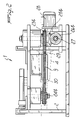
- the machine according to the invention comprises a main structure 2 which supports means 3 for axially locking a cop or support 4 of a spool to be cleaned and means 5 for scraping the residual thread 6 wound on the cop 4.
- Said scraping means 5 are movable along the lateral surface of the cop 4 in a direction which has an axial component with respect to the cop 4, so as to obtain the gradual axial removal of the residual thread 6 from the cop 4.
- the scraping means 5 comprise teeth 7 which are fixed to two chains 8 and 9 in which one portion, respectively designated by the reference numerals 8a and 9a, faces the lateral surface of the cop 4 to be cleaned.
- the teeth 7 are spaced along the extension of the corresponding chain, and there are pressure means 10 which act on the chains 8 and 9, more specifically on their portions 8a and 9a, towards the axis 4a of the cop 4, so as to produce an effective action of the teeth 7 during the translatory motion of said teeth along the lateral surface of the cop 4.
- the arrangement of the chains 8 and 9 is such that the portions 8a and 9a face two diametrically mutually opposite regions of the cop 4.
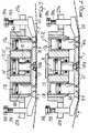
- the pressure means comprise shoes 11 and 12 which laterally face, on opposite sides, the lateral surface of the cop 4; each shoe forms a lateral support for the portion 8a or 9a of the chains 8 and 9 which is arranged opposite the cop 4.
- said shoes are movable by control towards or away from the cop 4 so as to facilitate the operations for loading and unloading the cop 4 in and from the machine.
- each one of the shoes 11 and 12 is mounted so that it can slide, along a direction that lies substantially at right angles to the axis 4a, on a support 13 which is fixed to the main structure 2.
- An intermediate portion of the shoe 11 or 12, located in the region that lies opposite to the side directed towards the cop 4, is fixed to the end of the stem 14a of a piston 14 which can slide within a cylindrical chamber 15 formed by the support 13.
- the chamber 15 and the piston 14 constitute, as a whole, a double-action pneumatic piston by means of which the shoe 11 or 12 is moved towards or away from the axis 4a of the cop 4.
- the secondary pistons 16a and 16b and the corresponding chamber 17a and 17b which can be supplied with compressed air, constitute as a whole two pneumatic springs which oppose the distancing of the shoe 11 or 12 from the cop 4.
- the movement of the shoe 11 or 12 towards the cop 4 is limited by two mechanical stroke limiters which are connected to the longitudinal ends of the corresponding shoe 11 or 12 and are constituted, in the illustrated embodiment, by nuts 18a and 18b which couple to two threaded shafts 19a and 19b which are connected to the ends of the shoe 11 and 12 and are arranged parallel to the axis of the piston 14.
- the nuts 18a and 18b which can be screwed along the corresponding threaded shaft 19a and 19b so as to vary the extent of the translatory motion of the shoe 11 or 12, abut against or check the shoulders 20a and 20b formed by the support 13.
- Each shoe 11 or 12 has a profile with which the portion 8a or 9a of the corresponding chain makes contact; at least one central portion 21 of said profile has a profile that is substantially parallel to the directrices of the lateral surface of the cop 4 which face said shoe.
- Said central portion 21 is preceded, along the direction of the advancement of the chain along the corresponding shoe, by an initial segment 22 that moves gradually towards the cop 4.
- the transition from the initial segment 22 to the central portion 21 occurs in a region that is spaced from the axial end of the cop 4 which lies opposite to the end through which the residual thread 6 is removed.
- the teeth 7 engage the residual thread 6 to be removed starting from a region of said residual thread that is spaced from the axial end of the cop 4 which lies opposite to the axial end from which the residual thread is removed.
- the two chains 8 and 9 wind around two pairs of sprockets designated respectively by the reference numerals 23a, 24a, 23b, and 24b.
- the sprockets 23a and 23b are connected, by means of two pairs of bevel gears 25a, 26a and 25b, 26b, to a same shaft 27 which is connected to the output shaft of a gearmotor 28 which thus drives the two chains 8 and 9.
- the means 3 for axially locking the cop 4 are constituted by two oppositely arranged pins, respectively designated by the reference numerals 29 and 30, which are arranged coaxially to each other along an axis that constitutes the axis 4a of the cop fitted on the machine. At least one of the two pins 29 or 30 is axially movable, in a per se known manner, with respect to the other pin, so as to axially lock the cop 4 or render possible its removal at the end of the cleaning operation.
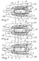
- the cop or support 4 is placed between the pins 29 and 30 that lock it axially.
- the shoes 11 and 12 are pushed towards the cop by the piston 14 and by the secondary pistons 16a and 16b, while the gearmotor 28 drives the chains 8 and 9.
- the teeth 7 located along the chains 8 and 9 gradually make contact with the residual thread 6 present on the cop 4 and gradually remove it axially from the cop 4.
- the first tooth 7 that makes contact with the residual thread 6 located on the cop 4 engages the residual thread 6 in a region of said residual thread which is spaced from the axial end of the cop 4, i.e. with a portion of the residual thread 6 which is spaced from the corresponding axial end of said residual thread.
- the cleaned cop 4 is disengaged by the pins 29 and 30 and replaced with another cop to be cleaned.
- the materials employed, as well as the dimensions, may be any according to the requirements and the state of the art.
Landscapes
- Spinning Or Twisting Of Yarns (AREA)
Applications Claiming Priority (2)
| Application Number | Priority Date | Filing Date | Title |
|---|---|---|---|
| ITMI932480 | 1993-11-23 | ||
| IT93MI002480A IT1265215B1 (it) | 1993-11-23 | 1993-11-23 | Macchina per la pulitura di tubetti o supporti di rocche di filati per l'industria tessile |
Publications (1)
| Publication Number | Publication Date |
|---|---|
| EP0654437A1 true EP0654437A1 (de) | 1995-05-24 |
Family
ID=11367244
Family Applications (1)
| Application Number | Title | Priority Date | Filing Date |
|---|---|---|---|
| EP94118296A Withdrawn EP0654437A1 (de) | 1993-11-23 | 1994-11-21 | Maschine zur Reinigung von Kopsen oder Fadenspulenhaltern für die Textilindustrie |
Country Status (2)
| Country | Link |
|---|---|
| EP (1) | EP0654437A1 (de) |
| IT (1) | IT1265215B1 (de) |
Cited By (1)
| Publication number | Priority date | Publication date | Assignee | Title |
|---|---|---|---|---|
| EP2952463A1 (de) | 2014-06-06 | 2015-12-09 | Cotonificio Olcese S.p.A. | Maschine zur reinigung von kopsen oder trägern von garnkonussen für die textilindustrie |
Citations (4)
| Publication number | Priority date | Publication date | Assignee | Title |
|---|---|---|---|---|
| DE1078510B (de) * | 1958-03-19 | 1960-03-24 | Georg Roehl | Spulenabstreifvorrichtung fuer die Schusspulen von Webstuehlen |
| CH372991A (de) * | 1959-08-03 | 1963-10-31 | Roehl Georg | Endlose Rollenkette, insbesondere für Spulenabstreifvorrichtungen |
| EP0053090A1 (de) * | 1980-11-20 | 1982-06-02 | Felix Mannhart AG | Verfahren und Einrichtung zum Entfernen eines Garnrestes von einem Wickelkörper |
| DE4221348A1 (de) * | 1991-06-29 | 1993-01-07 | Murata Machinery Ltd | Spulen- und huelsentransportvorrichtung fuer eine spulmaschine |
-
1993
- 1993-11-23 IT IT93MI002480A patent/IT1265215B1/it active IP Right Grant
-
1994
- 1994-11-21 EP EP94118296A patent/EP0654437A1/de not_active Withdrawn
Patent Citations (4)
| Publication number | Priority date | Publication date | Assignee | Title |
|---|---|---|---|---|
| DE1078510B (de) * | 1958-03-19 | 1960-03-24 | Georg Roehl | Spulenabstreifvorrichtung fuer die Schusspulen von Webstuehlen |
| CH372991A (de) * | 1959-08-03 | 1963-10-31 | Roehl Georg | Endlose Rollenkette, insbesondere für Spulenabstreifvorrichtungen |
| EP0053090A1 (de) * | 1980-11-20 | 1982-06-02 | Felix Mannhart AG | Verfahren und Einrichtung zum Entfernen eines Garnrestes von einem Wickelkörper |
| DE4221348A1 (de) * | 1991-06-29 | 1993-01-07 | Murata Machinery Ltd | Spulen- und huelsentransportvorrichtung fuer eine spulmaschine |
Cited By (1)
| Publication number | Priority date | Publication date | Assignee | Title |
|---|---|---|---|---|
| EP2952463A1 (de) | 2014-06-06 | 2015-12-09 | Cotonificio Olcese S.p.A. | Maschine zur reinigung von kopsen oder trägern von garnkonussen für die textilindustrie |
Also Published As
| Publication number | Publication date |
|---|---|
| ITMI932480A1 (it) | 1995-05-23 |
| ITMI932480A0 (it) | 1993-11-23 |
| IT1265215B1 (it) | 1996-10-31 |
Similar Documents
| Publication | Publication Date | Title |
|---|---|---|
| EP0741808B1 (de) | Steuerbare auslaufbremse, fadenliefervorrichtung sowie projektil- oder greiferwebmaschine | |
| US4097976A (en) | Spinning tube stripping means | |
| US2690771A (en) | Heddle | |
| JPS5813659B2 (ja) | 織機の緯糸把持装置 | |
| KR20030023688A (ko) | 열가소성 필라멘트로 형성된 스트랜드 절단용 조립체 및방법 | |
| US3444601A (en) | Mechanism and method for positioning reeds | |
| JPH03130433A (ja) | 停止箇所ができ易い織物のための織機 | |
| US811358A (en) | Beaming-machine. | |
| DE3045173C2 (de) | Vorrichtung für die konstante Zufuhr von Garn an Textilmaschinen | |
| US2823706A (en) | Loom temple mechanism | |
| US2369636A (en) | Method and apparatus for molding loop pickers | |
| KR820002275B1 (ko) | 드럼형 보빈의 잔사 제거장치 | |
| CN114427137A (zh) | 一种纺织服装加工用集成送线装置 | |
| US2335111A (en) | Circular loom | |
| US2950518A (en) | Self-compensating comb | |
| US2099461A (en) | Fabric treating machine | |
| ITMI932480A1 (it) | Macchina per la pulitura di tubetti o supporti di rocche di filati per l'industria tessile | |
| KR960008313Y1 (ko) | 북직기의 컷터 | |
| US2886070A (en) | Loom thread cutter | |
| US2865542A (en) | Hosiery inspection machines | |
| US2413881A (en) | Separating device for leased warp threads in weaving-preparing machines | |
| US2478157A (en) | Loom harness | |
| US4014082A (en) | Method and equipment for removing reeling waste | |
| US2815045A (en) | Loom temple rolls | |
| KR900010549Y1 (ko) | 드럼형보빈의 잔사제거장치 |
Legal Events
| Date | Code | Title | Description |
|---|---|---|---|
| PUAI | Public reference made under article 153(3) epc to a published international application that has entered the european phase |
Free format text: ORIGINAL CODE: 0009012 |
|
| AK | Designated contracting states |
Kind code of ref document: A1 Designated state(s): AT CH DE ES IT LI |
|
| STAA | Information on the status of an ep patent application or granted ep patent |
Free format text: STATUS: THE APPLICATION HAS BEEN WITHDRAWN |
|
| 18W | Application withdrawn |
Withdrawal date: 19951016 |