EP0654584A1 - Hydrostatische Radialkolbenmaschine mit axialer Schubkompensation - Google Patents
Hydrostatische Radialkolbenmaschine mit axialer Schubkompensation Download PDFInfo
- Publication number
- EP0654584A1 EP0654584A1 EP94114848A EP94114848A EP0654584A1 EP 0654584 A1 EP0654584 A1 EP 0654584A1 EP 94114848 A EP94114848 A EP 94114848A EP 94114848 A EP94114848 A EP 94114848A EP 0654584 A1 EP0654584 A1 EP 0654584A1
- Authority
- EP
- European Patent Office
- Prior art keywords
- rotors
- hydrostatic
- machine according
- intermediate floor
- hydrostatic machine
- Prior art date
- Legal status (The legal status is an assumption and is not a legal conclusion. Google has not performed a legal analysis and makes no representation as to the accuracy of the status listed.)
- Granted
Links
- 230000002706 hydrostatic effect Effects 0.000 title claims abstract description 44
- 238000006073 displacement reaction Methods 0.000 claims description 6
- 238000010276 construction Methods 0.000 claims 1
- 230000005540 biological transmission Effects 0.000 description 3
- 230000001419 dependent effect Effects 0.000 description 1
- 238000011161 development Methods 0.000 description 1
- 230000018109 developmental process Effects 0.000 description 1
- 238000007789 sealing Methods 0.000 description 1
Images



Classifications
-
- F—MECHANICAL ENGINEERING; LIGHTING; HEATING; WEAPONS; BLASTING
- F01—MACHINES OR ENGINES IN GENERAL; ENGINE PLANTS IN GENERAL; STEAM ENGINES
- F01B—MACHINES OR ENGINES, IN GENERAL OR OF POSITIVE-DISPLACEMENT TYPE, e.g. STEAM ENGINES
- F01B13/00—Reciprocating-piston machines or engines with rotating cylinders in order to obtain the reciprocating-piston motion
- F01B13/04—Reciprocating-piston machines or engines with rotating cylinders in order to obtain the reciprocating-piston motion with more than one cylinder
- F01B13/06—Reciprocating-piston machines or engines with rotating cylinders in order to obtain the reciprocating-piston motion with more than one cylinder in star arrangement
- F01B13/061—Reciprocating-piston machines or engines with rotating cylinders in order to obtain the reciprocating-piston motion with more than one cylinder in star arrangement the connection of the pistons with the actuated or actuating element being at the outer ends of the cylinders
- F01B13/063—Reciprocating-piston machines or engines with rotating cylinders in order to obtain the reciprocating-piston motion with more than one cylinder in star arrangement the connection of the pistons with the actuated or actuating element being at the outer ends of the cylinders with two or more series radial piston-cylinder units
-
- F—MECHANICAL ENGINEERING; LIGHTING; HEATING; WEAPONS; BLASTING
- F04—POSITIVE - DISPLACEMENT MACHINES FOR LIQUIDS; PUMPS FOR LIQUIDS OR ELASTIC FLUIDS
- F04B—POSITIVE-DISPLACEMENT MACHINES FOR LIQUIDS; PUMPS
- F04B1/00—Multi-cylinder machines or pumps characterised by number or arrangement of cylinders
- F04B1/04—Multi-cylinder machines or pumps characterised by number or arrangement of cylinders having cylinders in star- or fan-arrangement
- F04B1/10—Multi-cylinder machines or pumps characterised by number or arrangement of cylinders having cylinders in star- or fan-arrangement the cylinders being movable, e.g. rotary
- F04B1/107—Multi-cylinder machines or pumps characterised by number or arrangement of cylinders having cylinders in star- or fan-arrangement the cylinders being movable, e.g. rotary with actuating or actuated elements at the outer ends of the cylinders
- F04B1/1071—Multi-cylinder machines or pumps characterised by number or arrangement of cylinders having cylinders in star- or fan-arrangement the cylinders being movable, e.g. rotary with actuating or actuated elements at the outer ends of the cylinders with rotary cylinder blocks
- F04B1/1074—Multi-cylinder machines or pumps characterised by number or arrangement of cylinders having cylinders in star- or fan-arrangement the cylinders being movable, e.g. rotary with actuating or actuated elements at the outer ends of the cylinders with rotary cylinder blocks with two or more serially arranged radial piston-cylinder units
Definitions
- the present invention relates to a hydrostatic radial piston machine according to the preamble of patent claim 1.
- Double-flow radial piston machines constructed according to the system of axial thrust compensation for two rotors are known; in these machines, the rotors are fixed on a shaft so that they cannot rotate. Basically, based on this arrangement, both a hydrostatic pump and a hydrostatic motor can be represented. With regard to the prior art, reference is made, for example, to ...
- the object on which the present invention is based is to specify a hydrostatic radial piston machine of the generic type in which the axial forces on the axis can be compensated.
- the system should be able to represent a hydrostatic pump with one or two flows, a corresponding hydrostatic motor and a hydrostatic transmission.
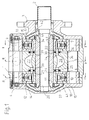
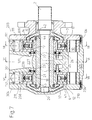
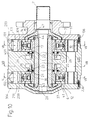
- All of the exemplary embodiments of hydrostatic radial piston machines shown in FIGS. 1 to 11 have a housing 1 (FIG. 1), 201 (FIG. 4), 301 (FIG. 7), 401 (FIG. 10), which has two, by means of an intermediate floor 5 (FIG. 1), 205 (FIG. 4), 305 (FIG. 7), 405 (FIG. 10). These interiors are closed from both sides via a housing cover 3, 4 (FIG. 1), 103, 204 (FIG. 4), 203, 304 (FIG. 7, FIG. 10).
- a lifting ring 8, 9 (see FIG. 1), 109, 208 (see FIGS. 4, 7, 10) is mounted in each of the two subspaces (interior) 6, 7, both of which have at least one position shaft 10 are connected.
- the two subspaces leave enough space to adjust the lifting rings 8, 9 of the hydrostatic pump according to FIG. 1 - as shown in FIG. 3 - by means of two adjusting pistons 32, 31 via a connecting shaft 11 and thus the stroke volume per revolution of the hydrostatic radial piston machine to a desired specific size.
- the conjugated cam rings 109, 208 can be adjusted independently of one another with the aid of adjusting pistons 131, 132, 231, 232 (see reference numerals 111, 211).
- the drive or output of the machine is via input and output shafts 2, 20 (FIG. 1, FIG. 7, FIG. 10) or 102, 202 (see FIG. 4) and via drivers 41, 42 each on a so-called cylinder star forming rotor 18, 19 passed.
- the rotors 18, 19 have lateral control slots 21, 22 which correspond to kidney-shaped channels 23, 24 incorporated in axially arranged control disks 25, 26.
- the axial These channels 23, 24 in the control disks 25, 26 are sealed by means of elastic sealing elements 38, 39.
- the known radial piston machines have an axis 43 which is fastened in the respective intermediate base 5, 205, 305, 405 and at the ends of which the rotors 18, 19 are mounted on the one hand between thrust washers 37, 44 and on the other hand the control discs 25, 26.
- a lifting ring 8, 9 (FIG. 1) or 109, 208 (FIG. 4, FIG. 7, FIG. 10) is provided for each rotor 18, 19, both of which are provided via a bearing shaft 10 in the respective intermediate floor 5, 205, 305, 405 are stored.
- the displacement elements serving the function or use as a hydrostatic radial piston machine each consisting of the functional connection of a slide shoe or a slide block 14 and one articulated therewith connected (displacement) piston 15 exist.
- These pistons 15 are each arranged in radial bores 16, 17 of one of the rotors 18, 19, which in turn are mounted such that they can be rotated easily, but are axially fixed — as already mentioned — driven or driven off via the drivers 41, 42.
- the rotors 18, 19 are coordinated with one another as follows: As already mentioned, mutually facing axial lateral control slots 21, 22 are provided in the radial bores 16, 17 of the rotors 18, 19, through which the bores 16, 17 are open to the respective intermediate floor 5, 205, 305, 405.
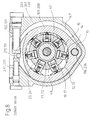
- the control slots 21, 22 in turn correspond to the kidney-shaped channels 23, 24 incorporated in the control disks (axial disks) 25, 26 (compare FIGS. 3, 6, 9, 11).
- the control disks 25, 26 are in corresponding recesses are inserted on both sides of the intermediate floor 5, 205, 305, 405.
- the axial thrust resulting from the pressurization of the (displacement) pistons 15 and the control slots 21, 22 is due to the clamping of the axis 43 in the intermediate floor 5, 205, 305, 405 between the control disk 26 supported thereon and a thrust washer 44 or on the intermediate floor 5, 205, 305, 405 supporting control disk 25 and a thrust washer 37 and thus not on the housing cover 3, 4; 103, 204; 203, 304 transmitted.
- the two thrust washers 37, 44 are each preloaded relative to a collar 33, 34 on the axis 43, that the distance between the thrust washers and the intermediate floor or the control discs 25, 26 is slightly larger than the width of the rotor 18, 19 corresponds.
Landscapes
- Engineering & Computer Science (AREA)
- Mechanical Engineering (AREA)
- General Engineering & Computer Science (AREA)
- Reciprocating Pumps (AREA)
- Details Of Reciprocating Pumps (AREA)
- Compressors, Vaccum Pumps And Other Relevant Systems (AREA)
- Hydraulic Motors (AREA)
- Magnetic Bearings And Hydrostatic Bearings (AREA)
Abstract
Description
- Die vorliegende Erfindung betrifft eine hydrostatische Radialkolbenmaschine nach dem Oberbegriff des Patentanspruchs 1.
- Zweiflutige, nach dem System der axialen Schubkompensation für zwei Rotoren aufgebaute Radialkolbenmaschinen sind bekannt; bei diesen Maschinen sitzen die Rotoren drehfest auf einer Welle. Grundsätzlich sind aufbauend auf dieser Anordnung sowohl eine hydrostatische Pumpe, als auch ein hydrostatischer Motor darstellbar. Zum Stand der Technik wird beispielsweise verwiesen auf ...
- Die der vorliegenden Erfindung zugrunde liegende Aufgabe besteht darin, eine hydrostatische Radialkolbenmaschine der gattungsgemäßen Art anzugeben, bei der die axialen Kräfte auf der Achse kompensiert werden können. Vom System her soll dabei gleichermaßen eine hydrostatische Pumpe mit ein oder zwei Strömen, ein entsprechender hydrostatischer Motor und ein hydrostatisches Getriebe dargestellt werden können.
- Diese Aufgabe wird durch die im kennzeichnenden Teil des Patentanspruchs 1 angegebenen Merkmale gelöst.
- Die besonderen Vorteile dieser Konfigurationen bestehen darin, daß sowohl die axialen, als auch die radialen Kräfte im Inneren der Radialkolbenmaschine aufgenommen werden, so daß über die jeweiligen Außenflächen keine Geräusche nach außen abgegeben beziehungsweise abgestrahlt werden.
- Besondere Weiterbildungen und Ausgestaltungen der Erfindung sind Gegenstand der Unteransprüche.
- Die Einzelheiten der erfindungsgemäßen hydrostatischen Radialkolbenmaschine werden im folgenden anhand der Zeichnung näher erläutert. Diese zeigt in
- Fig. 1
- einen Längsschnitt durch eine hydrostatische Pumpe beziehungsweise einen hydrostatischen Motor;
- Fig. 2
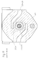
- einen Querschnitt durch die hydrostatische Maschine gemäß Fig. 1 längs der Schnittlinie II-II;
- Fig. 3
- einen Querschnitt durch die hydrostatische Maschine gemäß Fig. 1 längs der Schnittlinie III-III;
- Fig. 4
- einen Längsschnitt durch ein hydrostatisches Getriebe;
- Fig. 5
- einen Querschnitt durch die hydrostatische Maschine gemäß Fig. 4 längs der Schnittlinie V-V;
- Fig. 6
- einen Querschnitt durch die hydrostatische Maschine gemäß Fig. 4 längs der Schnittlinie IV-IV;
- Fig. 7
- einen Längsschnitt durch eine hydrostatische Zweistrom-Pumpe beziehungsweise einen hydrostatischen Zweistrom-Motor;
- Fig. 8
- einen Querschnitt durch die hydrostatische Maschine gemäß Fig. 7 längs der Schnittlinie VII-VII;
- Fig. 9
- einen Querschnitt durch die hydrostatische Maschine gemäß Fig. 7 längs der Schnittlinie VI-VI;
- Fig. 10
- einen Längsschnitt durch eine hydrostatische Zweistrom-Pumpe beziehungsweise einen hydrostatischen Zweistrom-Motor für unterschiedliche Drücke;
- Fig. 11
- einen Querschnitt durch die hydrostatische Maschine gemäß Fig. 10 längs der Schnittlinie VIII-VIII.
- Sämtliche in den Fig. 1 bis Fig. 11 dargestellten Ausführungsbeispiele von hydrostatischen Radialkolbenmaschinen weisen ein Gehäuse 1 (Fig. 1), 201 (Fig. 4), 301 (Fig. 7), 401 (Fig. 10) auf, das zwei, durch jeweils einen Zwischenboden 5 (Fig. 1), 205 (Fig. 4), 305 (Fig. 7), 405 (Fig. 10) getrennte Innenräume hat. Diese Innenräume sind von beiden Seiten her über je einen Gehäusedeckel 3, 4 (Fig. 1), 103, 204 (Fig. 4), 203, 304 (Fig. 7, Fig. 10) abgeschlossen. In den jeweiligen beiden Teilräumen (Innenraum) 6, 7 ist je ein Hubring 8, 9 (vergleiche Fig. 1), 109, 208 (vergleiche Fig. 4, Fig. 7, Fig. 10) gelagert, welche beide über mindestens eine Lagewelle 10 miteinander verbunden sind.
- Die beiden Teilräume lassen dabei genügend Platz, um die Hubringe 8, 9 der hydrostatischen Pumpe nach Fig. 1 - wie in Fig. 3 dargestellt - mittels zweier Verstellkolben 32, 31 über eine Verbindungswelle 11 zu verstellen und damit das Hubvolumen pro Umdrehung der hydrostatischen Radialkolbenmaschine auf eine gewünschte spezifische Größe einzustellen. Bei den in Fig. 4, Fig. 7 und Fig. 10 dargestellten hydrostatischen Radialkolbenmaschinen können die konjugierten Hubringe 109, 208 mit Hilfe von Verstellkolben 131, 132, 231, 232 unabhängig voneinander verstellt werden (vergleiche Bezugszeichen 111, 211).
- Der Antrieb beziehungsweise Abtrieb der Maschine wird über An- beziehungsweise Abtriebswellen 2, 20 (Fig. 1, Fig. 7, Fig. 10) beziehungsweise 102, 202 (vergleiche Fig. 4) und über Mitnehmer 41, 42 auf je einen einen sogenannten Zylinderstern bildenden Rotor 18, 19 geleitet. Die Rotoren 18, 19 weisen seitliche Steuerschlitze 21, 22 auf, die mit in axial angeordneten Steuerscheiben 25, 26 eingearbeiteten nierenförmigen Kanälen 23, 24 korrespondieren. Die axiale Abdichtung dieser Kanäle 23, 24 in den Steuerscheiben 25, 26 erfolgt über elastische Dichtelemente 38, 39.
- Die bekannten Radialkolbenmaschinen weisen eine Achse 43 auf, die im jeweiligen Zwischenboden 5, 205, 305, 405 befestigt ist und an deren Enden die Rotoren 18, 19 einerseits zwischen Anlaufscheiben 37, 44 und andererseits den Steuerscheiben 25, 26 gelagert sind.
- Für jeden Rotor 18, 19 ist je ein Hubring 8, 9 (Fig. 1) beziehungsweise 109, 208 (Fig. 4, Fig. 7, Fig. 10) vorgesehen, welche beide über eine Lagerwelle 10 im jeweiligen Zwischenboden 5, 205, 305, 405 gelagert sind.
- An der Innenseite 12, 13 der Hubringe 8, 9 beziehungsweise 109, 208 gleiten - in an sich bekannter Weise - die der Funktion beziehungsweise Verwendung als hydrostatische Radialkolbenmaschine dienenden Verdrängerelemente, die jeweils aus der funktionalen Verbindung eines Gleitschuhs oder eines Gleitsteins 14 und eines gelenkig damit verbundenen (Verdränger-) Kolbens 15 bestehen. Diese Kolben 15 sind in radialen Bohrungen 16, 17 je eines der Rotoren 18, 19 angeordnet, die ihrerseits leicht verdrehbar gelagert, aber axial fixiert - wie bereits erwähnt - über die Mitnehmer 41, 42 angetrieben werden beziehungsweise abtreiben.
- Die im Vorstehenden beschriebene Konfiguration entspricht abgesehen davon, daß noch keine Angaben über den Förderstrom beziehungsweise die Pumpfunktion gemacht wurden, dem Stand der Technik insoweit, als die Rotoren 18, 19 an sich bekannt sind. Die besondere Konfiguration besteht nun darin, daß die hydrostatische Radialkolbenmaschine nicht von zwei Rotoren 18, 19 auf einer Welle als Lager ausgeht, sondern von einer Achse 43, auf der die beiden Rotoren leicht drehbar gelagert sind, so daß ein asynchrones Arbeiten der Rotoren 18, 19 möglich ist und die axialen Kräfte auf diese Achse 43 kompensiert werden.
- Die Rotoren 18, 19 sind im Hinblick auf ihre spezifische Funktion als Pumpen- beziehungsweise Motorelement wie folgt aufeinander abgestimmt:
In den radialen Bohrungen 16, 17 der Rotoren 18, 19 sind - wie bereits erwähnt - einander zugewandte axiale seitliche Steuerschlitze 21, 22 vorgesehen, über die die Bohrungen 16, 17 zum jeweiligen Zwischenboden 5, 205, 305, 405 hin offen sind. Die Steuerschlitze 21, 22 korrespondieren ihrerseits mit den in den Steuerscheiben (Axialscheiben) 25, 26 eingearbeiteten nierenförmigen (vergleiche Fig. 3, Fig. 6, Fig. 9, Fig. 11) Kanälen 23, 24. Die Steuerscheiben 25, 26 sind in entsprechenden Ausnehmungen auf beiden Seiten des Zwischenbodens 5, 205, 305, 405 eingelegt. Im Zwischenboden 5, 205, 305, 405 selbst sind korrespondierend zu den genannten Steuerschlitzen 21, 22 und den nierenförmigen Kanälen 23, 24 Verbindungskanäle 27, 28 (Fig. 1), 127, 128, 228 (Fig. 4); 127, 128, 228 (Fig. 7); 128, 228, 328, 428 (Fig. 10) eingearbeitet, so daß beide Rotoren 18, 19 über ihre Verdrängerelemente jeweils gemeinsam als Pumpe beziehungsweise als hydrostatische Maschine zu arbeiten vermögen. - Der durch die Druckbeaufschlagung der (Verdränger-) Kolben 15 und der Steuerschlitze 21, 22 entstehende axiale Schub wird aufgrund der Einspannung der Achse 43 im Zwischenboden 5, 205, 305, 405 zwischen der sich an diesem abstützenden Steuerscheibe 26 und einer Anlaufscheibe 44 beziehungsweise der sich am Zwischenboden 5, 205, 305, 405 abstützenden Steuerscheibe 25 und einer Anlaufscheibe 37 aufgenommen und somit nicht auf die Gehäusedeckel 3, 4; 103, 204; 203, 304 übertragen. Die beiden Anlaufscheiben 37, 44 sind dabei jeweils gegenüber einem Bund 33, 34 auf der Achse 43 so vorgespannt, daß der Abstand zwischen den Anlaufscheiben und dem Zwischenboden beziehungsweise den Steuerscheiben 25, 26 etwas größer ist, als es der Breite des Rotors 18, 19 entspricht.
- Die im Vorstehenden erläuterte Konfiguration und die in Verbindung damit beschriebenen Zusammenhänge beziehen sich in erster Linie auf eine hydrostatische Radialkolbenmaschine mit zwei auf einer Achse leicht verdrehbar gelagerten Rotoren, die eine Mehrzahl von radial verlaufenden Bohrungen mit an der Innenseite gleitende Verdrängerelemente aufweist, wobei die Bohrungen zur Steuerung der Förderung des Druckmediums über Steuerschlitze mit seitlich an den Rotoren mündenden Förderkanälen verbunden sind.
- Je nach spezifischer Ausführung als Pumpe, als Motor oder als Getriebe werden das Gehäuse 1, 201, 301, 401 und die Gehäusedeckel (3, 4); (103, 204); (203, 304), sowie die An- / Abtriebswelle 2, 20; 102, 202 modifiziert.
- Es entsteht so je nach Anordnung entsprechend
- nach Fig. 1 eine hydrostatische Pumpe beziehungsweise ein hydrostatischer Motor,
- nach Fig. 4 ein hydrostatisches Getriebe,
- nach Fig. 7 eine hydrostatische Zweistrom-Pumpe beziehungsweise ein hydrostatischer Zweistrom-Motor für
- vergleiche Fig. 10 mögliche unterschiedliche Drücke in den Kanälen 128, 228, 328, 428.
Claims (7)
- Hydrostatische Radialkolbenmaschine mit zwei auf einer Achse (43) leicht verdrehbar gelagerten Rotoren (18, 19), die eine Mehrzahl von radial verlaufenden Bohrungen (16, 17) mit an der Innenseite eines Hubrings (8, 9, 109, 208) gleitenden Verdrängerelementen (Kolben 15 mit Gleitstein 14) aufweist, wobei die Bohrungen (16, 17) zur Steuerung zur Förderung des Druckmediums über Steuerschlitze (21, 22) mit seitlich an den Rotoren mündenden Förderkanälen (Hoch- / Niederdruck) ver bunden sind,
dadurch gekennzeichnet,
daß die beiden Rotoren (18, 19) leicht drehbar auf einer fest in einem Zwischenboden (5, 205, 305, 405) eingebauten Achse (43) gelagert ist,
daß der Zwischenboden (5, 205, 305, 405) zwischen den Rotoren (18, 19) liegt,
daß an den Enden der Achse (43) Anlaufscheiben (37, 44) angebracht sind, die die durch das Druckmedium in den Steuerschlitzen (21, 22) der Rotoren (18, 19) hervorgerufenen axialen Kräfte aufnehmen, und
daß die Hubringe (8, 9; 109, 208) über eine gemeinsame Verbindungswelle (10) im Zwischenboden (5, 205, 305, 405) gelagert sind. - Hydrostatische Maschine nach Anspruch 1,
dadurch gekennzeichnet,
daß für jeden Rotor (18, 19) ein Bund (33, 34) auf der Achse (43) vorgesehen ist, gegen den die Anlaufscheiben (37, 44) gespannt sind, so daß der Abstand zwischen den Anlaufscheiben (37, 44) und dem Zwischenboden (5, 205, 305, 405) beziehungsweise den Steuerscheiben (25, 26) etwas größer ist als es der Breite des Rotors (18, 19) entspricht. - Hydrostatische Maschine nach Anspruch 1 oder 2,
dadurch gekennzeichnet,
daß beide Verdrängervolumina über eine gemeinsame Stelleinrichtung veränderbar sind. - Hydrostatische Maschine nach Anspruch 1 oder 2,
zum Aufbau eines Kompaktgetriebes in sekundär geregelter Ausführung,
dadurch gekennzeichnet,
daß die Druckseiten beider Rotoren miteinander verbunden und die Niederdruckseiten beider Rotoren getrennt sind. - Hydrostatische Maschine nach Anspruch 1 oder 2,
zum Aufbau von Pumpen oder Motoren mit unterschiedlichen Betriebsdrücken und im Motorfall unterschiedlichen Drehzahlen,
dadurch gekennzeichnet,
daß die beiden Niederdruckseiten miteinander verbunden und die Hochdruckseiten getrennt sind. - Hydrostatische Maschine nach Anspruch 1 oder 2,
dadurch gekennzeichnet,
daß jeder Rotor (18, 19) einen eigenen Hoch- und Niederdruckanschluß aufweist. - Hydrostatische Maschine nach Anspruch 1 oder 2,
dadurch gekennzeichnet,
daß die beiden Rotoren (18, 19) unterschiedliche Verdrängervolumina aufweisen.
Applications Claiming Priority (2)
| Application Number | Priority Date | Filing Date | Title |
|---|---|---|---|
| DE4335513 | 1993-10-19 | ||
| DE4335513 | 1993-10-19 |
Publications (2)
| Publication Number | Publication Date |
|---|---|
| EP0654584A1 true EP0654584A1 (de) | 1995-05-24 |
| EP0654584B1 EP0654584B1 (de) | 1998-04-15 |
Family
ID=6500440
Family Applications (1)
| Application Number | Title | Priority Date | Filing Date |
|---|---|---|---|
| EP94114848A Expired - Lifetime EP0654584B1 (de) | 1993-10-19 | 1994-09-21 | Hydrostatische Radialkolbenmaschine mit axialer Schubkompensation |
Country Status (7)
| Country | Link |
|---|---|
| US (1) | US5622052A (de) |
| EP (1) | EP0654584B1 (de) |
| JP (1) | JPH084548A (de) |
| AT (1) | ATE165139T1 (de) |
| DE (1) | DE59405708D1 (de) |
| DK (1) | DK0654584T3 (de) |
| ES (1) | ES2117180T3 (de) |
Families Citing this family (8)
| Publication number | Priority date | Publication date | Assignee | Title |
|---|---|---|---|---|
| US6021635A (en) * | 1996-12-23 | 2000-02-08 | Parker-Hannifin Corporation | Dual orifice liquid fuel and aqueous flow atomizing nozzle having an internal mixing chamber |
| SE517873C2 (sv) * | 1997-04-10 | 2002-07-30 | Haegglunds Drives Ab | Kolv till en hydraulisk radialkolvmotor samt hydraulisk radialmotor med sådan kolv |
| US6151990A (en) * | 1998-05-06 | 2000-11-28 | Tecumseh Products Company | Hydrostatic transaxle having a casing split along one or more vertical planes |
| US6212994B1 (en) * | 1999-06-07 | 2001-04-10 | David A. Estrabrooks | Positive displacement rotary machine |
| JP4040355B2 (ja) | 2002-04-26 | 2008-01-30 | スガツネ工業株式会社 | ヒンジ |
| CN102720630B (zh) * | 2012-06-08 | 2014-09-24 | 燕山大学 | 双转子壳体转动凸轮连杆滚柱多速马达 |
| EP3513029B1 (de) * | 2016-09-16 | 2020-06-03 | Robert Bosch GmbH | Rotierender elektrohydraulischer stellantrieb |
| WO2018205015A1 (en) * | 2017-05-06 | 2018-11-15 | Kinetics Drive Solutions Inc. | Hydrostatic variator based on radial piston machines |
Citations (2)
| Publication number | Priority date | Publication date | Assignee | Title |
|---|---|---|---|---|
| DE2420853A1 (de) * | 1973-05-04 | 1974-11-21 | Breinlich Richard Dr | Von fluid durchstroemter doppelmotor mit freilauf |
| FR2376944A1 (fr) * | 1977-01-07 | 1978-08-04 | Bosch Gmbh Robert | Dispositif de reglage pour une machine a pistons radiaux multiple |
Family Cites Families (13)
| Publication number | Priority date | Publication date | Assignee | Title |
|---|---|---|---|---|
| DE83300C (de) * | ||||
| US2226481A (en) * | 1938-06-29 | 1940-12-24 | Eustace L Rose | Hydraulic transmission |
| US2818707A (en) * | 1950-10-09 | 1958-01-07 | Sturm Erwin | Rotary pump and motor hydraulic transmission |
| DE2301448C3 (de) * | 1973-01-12 | 1980-01-24 | Robert Bosch Gmbh, 7000 Stuttgart | Hydrostatische Radialkolbenpumpe |
| AT345103B (de) * | 1973-05-04 | 1978-08-25 | Eickmann Karl | Vierstroemige oder mehr als vierstroemige radialkolbenmaschine |
| DE2418164C3 (de) * | 1974-04-13 | 1978-12-14 | Voith Getriebe Kg, 7920 Heidenheim | Innenbeströmte Radialkolbenmaschine |
| EP0110910B1 (de) * | 1982-06-03 | 1989-03-01 | Unipat Ag | Hydrostatisches getriebe mit radialkolbenpumpe und -motor |
| DE3440219A1 (de) * | 1983-11-03 | 1985-05-15 | Unipat AG, Glarus | Hydrostatische maschine |
| US5042252A (en) * | 1990-02-22 | 1991-08-27 | Unipat Ag | Neutral shifting mechanism for hydrostatic transmission |
| DE4123675A1 (de) * | 1991-07-17 | 1993-01-21 | Bosch Gmbh Robert | Hydrostatische kolbenmaschine |
| DE9208850U1 (de) * | 1992-07-02 | 1992-09-10 | J.M. Voith Gmbh, 7920 Heidenheim | Hydrostatische Maschine mit axialem Schubausgleich |
| ATE129546T1 (de) * | 1992-09-04 | 1995-11-15 | Voith Gmbh J M | Hydrostatische maschine mit axialem schubausgleich. |
| US5400594A (en) * | 1992-09-04 | 1995-03-28 | Tecumseh Products Company | Slipper guide for a hydrostatic transmission |
-
1994
- 1994-09-21 DE DE59405708T patent/DE59405708D1/de not_active Expired - Fee Related
- 1994-09-21 ES ES94114848T patent/ES2117180T3/es not_active Expired - Lifetime
- 1994-09-21 AT AT94114848T patent/ATE165139T1/de not_active IP Right Cessation
- 1994-09-21 EP EP94114848A patent/EP0654584B1/de not_active Expired - Lifetime
- 1994-09-21 DK DK94114848T patent/DK0654584T3/da active
- 1994-10-19 US US08/325,809 patent/US5622052A/en not_active Expired - Fee Related
- 1994-10-19 JP JP6253149A patent/JPH084548A/ja active Pending
Patent Citations (2)
| Publication number | Priority date | Publication date | Assignee | Title |
|---|---|---|---|---|
| DE2420853A1 (de) * | 1973-05-04 | 1974-11-21 | Breinlich Richard Dr | Von fluid durchstroemter doppelmotor mit freilauf |
| FR2376944A1 (fr) * | 1977-01-07 | 1978-08-04 | Bosch Gmbh Robert | Dispositif de reglage pour une machine a pistons radiaux multiple |
Also Published As
| Publication number | Publication date |
|---|---|
| DK0654584T3 (da) | 1999-03-08 |
| JPH084548A (ja) | 1996-01-09 |
| ES2117180T3 (es) | 1998-08-01 |
| DE59405708D1 (de) | 1998-05-20 |
| ATE165139T1 (de) | 1998-05-15 |
| EP0654584B1 (de) | 1998-04-15 |
| US5622052A (en) | 1997-04-22 |
Similar Documents
| Publication | Publication Date | Title |
|---|---|---|
| DE2038965C3 (de) | Hydraulischer Motor | |
| EP0654584B1 (de) | Hydrostatische Radialkolbenmaschine mit axialer Schubkompensation | |
| DE4206101C2 (de) | Hydromechanisches Antriebssystem | |
| DE19849334B4 (de) | Hydrostatische Motoreinheit | |
| DE3029116A1 (de) | Hydraulischer motor | |
| EP1299644B1 (de) | Hydrotransformator | |
| EP0856638B1 (de) | Verstellbare Radialkolbenmaschine | |
| DE19642021B4 (de) | Hydrostatische Axialkolbenmaschine | |
| EP0602231B1 (de) | Hydrostatische maschine mit axialem schubausgleich | |
| DE3322549A1 (de) | Fluegelzellenpumpe mit veraenderlichem foerderhub fuer hydraulische betriebsmittel insbesondere von kraftfahrzeugen | |
| EP0585609B1 (de) | Hydrostatische Maschine mit axialem Schubausgleich | |
| DE19823508C2 (de) | Mobiles Arbeitsfahrzeug mit kompakter Achsbaugruppe | |
| DE3134537C2 (de) | Hydraulische Axialkolbenmaschine mit rotierenden Verdrängungskörpern | |
| DE4234055C2 (de) | Spiralkompressor | |
| DE19650270A1 (de) | Hydrostatische Axialkolbenmaschine | |
| DE19817162A1 (de) | Elektrohydraulischer Kompaktantrieb | |
| DE1453498A1 (de) | Hydraulischer Motor | |
| DE8521520U1 (de) | Mehrzylindermembranpumpe | |
| DE102005055729B4 (de) | Hydrostatische Antriebseinheit mit einem Axialkolbenmotor in Taumelscheibenbauweise und mit einem Differentialgetriebe | |
| DE1480720C3 (de) | Hydrostatische Lenkeinrichtung, insbesondere für Kraftfahrzeuge | |
| EP2998580B1 (de) | Stelleinrichtung einer hydrostatischen axialkolbenmaschine in schrägscheibenbauweise | |
| DE9208850U1 (de) | Hydrostatische Maschine mit axialem Schubausgleich | |
| DE1500421C (de) | Hydrostatisches Axialkolbengetriebe mit innerer Leistungsverzweigung , insbe sondere fur Kraftfahrzeuge | |
| DE2537552A1 (de) | Radialkolbenmaschine | |
| DD242453A1 (de) | Kolbenschiebersteuerung fuer hydrostatische radialkolbenmaschinen |
Legal Events
| Date | Code | Title | Description |
|---|---|---|---|
| PUAI | Public reference made under article 153(3) epc to a published international application that has entered the european phase |
Free format text: ORIGINAL CODE: 0009012 |
|
| AK | Designated contracting states |
Kind code of ref document: A1 Designated state(s): AT BE CH DE DK ES FR GB IT LI NL SE |
|
| 17P | Request for examination filed |
Effective date: 19950728 |
|
| 17Q | First examination report despatched |
Effective date: 19961205 |
|
| GRAG | Despatch of communication of intention to grant |
Free format text: ORIGINAL CODE: EPIDOS AGRA |
|
| GRAG | Despatch of communication of intention to grant |
Free format text: ORIGINAL CODE: EPIDOS AGRA |
|
| GRAH | Despatch of communication of intention to grant a patent |
Free format text: ORIGINAL CODE: EPIDOS IGRA |
|
| GRAH | Despatch of communication of intention to grant a patent |
Free format text: ORIGINAL CODE: EPIDOS IGRA |
|
| GRAA | (expected) grant |
Free format text: ORIGINAL CODE: 0009210 |
|
| AK | Designated contracting states |
Kind code of ref document: B1 Designated state(s): AT BE CH DE DK ES FR GB IT LI NL SE |
|
| REF | Corresponds to: |
Ref document number: 165139 Country of ref document: AT Date of ref document: 19980515 Kind code of ref document: T |
|
| REG | Reference to a national code |
Ref country code: CH Ref legal event code: EP |
|
| GBT | Gb: translation of ep patent filed (gb section 77(6)(a)/1977) |
Effective date: 19980415 |
|
| REF | Corresponds to: |
Ref document number: 59405708 Country of ref document: DE Date of ref document: 19980520 |
|
| ET | Fr: translation filed | ||
| ITF | It: translation for a ep patent filed | ||
| REG | Reference to a national code |
Ref country code: ES Ref legal event code: FG2A Ref document number: 2117180 Country of ref document: ES Kind code of ref document: T3 |
|
| PLBE | No opposition filed within time limit |
Free format text: ORIGINAL CODE: 0009261 |
|
| STAA | Information on the status of an ep patent application or granted ep patent |
Free format text: STATUS: NO OPPOSITION FILED WITHIN TIME LIMIT |
|
| REG | Reference to a national code |
Ref country code: DK Ref legal event code: T3 |
|
| 26N | No opposition filed | ||
| REG | Reference to a national code |
Ref country code: GB Ref legal event code: IF02 |
|
| PGFP | Annual fee paid to national office [announced via postgrant information from national office to epo] |
Ref country code: GB Payment date: 20030818 Year of fee payment: 10 |
|
| PGFP | Annual fee paid to national office [announced via postgrant information from national office to epo] |
Ref country code: ES Payment date: 20030910 Year of fee payment: 10 |
|
| PGFP | Annual fee paid to national office [announced via postgrant information from national office to epo] |
Ref country code: FR Payment date: 20030917 Year of fee payment: 10 |
|
| PGFP | Annual fee paid to national office [announced via postgrant information from national office to epo] |
Ref country code: AT Payment date: 20030919 Year of fee payment: 10 |
|
| PGFP | Annual fee paid to national office [announced via postgrant information from national office to epo] |
Ref country code: SE Payment date: 20030922 Year of fee payment: 10 Ref country code: BE Payment date: 20030922 Year of fee payment: 10 |
|
| PGFP | Annual fee paid to national office [announced via postgrant information from national office to epo] |
Ref country code: NL Payment date: 20030923 Year of fee payment: 10 |
|
| PGFP | Annual fee paid to national office [announced via postgrant information from national office to epo] |
Ref country code: DK Payment date: 20030924 Year of fee payment: 10 |
|
| PGFP | Annual fee paid to national office [announced via postgrant information from national office to epo] |
Ref country code: CH Payment date: 20030925 Year of fee payment: 10 |
|
| PGFP | Annual fee paid to national office [announced via postgrant information from national office to epo] |
Ref country code: DE Payment date: 20031002 Year of fee payment: 10 |
|
| PG25 | Lapsed in a contracting state [announced via postgrant information from national office to epo] |
Ref country code: GB Free format text: LAPSE BECAUSE OF NON-PAYMENT OF DUE FEES Effective date: 20040921 Ref country code: AT Free format text: LAPSE BECAUSE OF NON-PAYMENT OF DUE FEES Effective date: 20040921 |
|
| PG25 | Lapsed in a contracting state [announced via postgrant information from national office to epo] |
Ref country code: SE Free format text: LAPSE BECAUSE OF NON-PAYMENT OF DUE FEES Effective date: 20040922 Ref country code: ES Free format text: LAPSE BECAUSE OF NON-PAYMENT OF DUE FEES Effective date: 20040922 |
|
| PG25 | Lapsed in a contracting state [announced via postgrant information from national office to epo] |
Ref country code: LI Free format text: LAPSE BECAUSE OF NON-PAYMENT OF DUE FEES Effective date: 20040930 Ref country code: DK Free format text: LAPSE BECAUSE OF NON-PAYMENT OF DUE FEES Effective date: 20040930 Ref country code: CH Free format text: LAPSE BECAUSE OF NON-PAYMENT OF DUE FEES Effective date: 20040930 Ref country code: BE Free format text: LAPSE BECAUSE OF NON-PAYMENT OF DUE FEES Effective date: 20040930 |
|
| BERE | Be: lapsed |
Owner name: J.M. *VOITH G.M.B.H. Effective date: 20040930 |
|
| PG25 | Lapsed in a contracting state [announced via postgrant information from national office to epo] |
Ref country code: NL Free format text: LAPSE BECAUSE OF NON-PAYMENT OF DUE FEES Effective date: 20050401 Ref country code: DE Free format text: LAPSE BECAUSE OF NON-PAYMENT OF DUE FEES Effective date: 20050401 |
|
| EUG | Se: european patent has lapsed | ||
| GBPC | Gb: european patent ceased through non-payment of renewal fee |
Effective date: 20040921 |
|
| REG | Reference to a national code |
Ref country code: CH Ref legal event code: PL |
|
| PG25 | Lapsed in a contracting state [announced via postgrant information from national office to epo] |
Ref country code: FR Free format text: LAPSE BECAUSE OF NON-PAYMENT OF DUE FEES Effective date: 20050531 |
|
| NLV4 | Nl: lapsed or anulled due to non-payment of the annual fee |
Effective date: 20050401 |
|
| REG | Reference to a national code |
Ref country code: DK Ref legal event code: EBP |
|
| REG | Reference to a national code |
Ref country code: FR Ref legal event code: ST |
|
| PG25 | Lapsed in a contracting state [announced via postgrant information from national office to epo] |
Ref country code: IT Free format text: LAPSE BECAUSE OF NON-PAYMENT OF DUE FEES;WARNING: LAPSES OF ITALIAN PATENTS WITH EFFECTIVE DATE BEFORE 2007 MAY HAVE OCCURRED AT ANY TIME BEFORE 2007. THE CORRECT EFFECTIVE DATE MAY BE DIFFERENT FROM THE ONE RECORDED. Effective date: 20050921 |
|
| REG | Reference to a national code |
Ref country code: ES Ref legal event code: FD2A Effective date: 20040922 |
|
| BERE | Be: lapsed |
Owner name: J.M. *VOITH G.M.B.H. Effective date: 20040930 |