EP0654674A2 - Kabelverteilersystem mit Prüfung von Versorgungs- und Teilnehmeranschlussleitungen - Google Patents
Kabelverteilersystem mit Prüfung von Versorgungs- und Teilnehmeranschlussleitungen Download PDFInfo
- Publication number
- EP0654674A2 EP0654674A2 EP94308514A EP94308514A EP0654674A2 EP 0654674 A2 EP0654674 A2 EP 0654674A2 EP 94308514 A EP94308514 A EP 94308514A EP 94308514 A EP94308514 A EP 94308514A EP 0654674 A2 EP0654674 A2 EP 0654674A2
- Authority
- EP
- European Patent Office
- Prior art keywords
- line
- service
- cards
- user
- tester
- Prior art date
- Legal status (The legal status is an assumption and is not a legal conclusion. Google has not performed a legal analysis and makes no representation as to the accuracy of the status listed.)
- Withdrawn
Links
Images


Classifications
-
- H—ELECTRICITY
- H04—ELECTRIC COMMUNICATION TECHNIQUE
- H04L—TRANSMISSION OF DIGITAL INFORMATION, e.g. TELEGRAPHIC COMMUNICATION
- H04L49/00—Packet switching elements
- H04L49/55—Prevention, detection or correction of errors
- H04L49/552—Prevention, detection or correction of errors by ensuring the integrity of packets received through redundant connections
-
- H—ELECTRICITY
- H04—ELECTRIC COMMUNICATION TECHNIQUE
- H04Q—SELECTING
- H04Q1/00—Details of selecting apparatus or arrangements
- H04Q1/02—Constructional details
- H04Q1/14—Distribution frames
- H04Q1/145—Distribution frames with switches arranged in a matrix configuration
-
- H—ELECTRICITY
- H04—ELECTRIC COMMUNICATION TECHNIQUE
- H04L—TRANSMISSION OF DIGITAL INFORMATION, e.g. TELEGRAPHIC COMMUNICATION
- H04L49/00—Packet switching elements
- H04L49/10—Packet switching elements characterised by the switching fabric construction
- H04L49/101—Packet switching elements characterised by the switching fabric construction using crossbar or matrix
-
- H—ELECTRICITY
- H04—ELECTRIC COMMUNICATION TECHNIQUE
- H04L—TRANSMISSION OF DIGITAL INFORMATION, e.g. TELEGRAPHIC COMMUNICATION
- H04L49/00—Packet switching elements
- H04L49/25—Routing or path finding in a switch fabric
- H04L49/253—Routing or path finding in a switch fabric using establishment or release of connections between ports
-
- H—ELECTRICITY
- H04—ELECTRIC COMMUNICATION TECHNIQUE
- H04L—TRANSMISSION OF DIGITAL INFORMATION, e.g. TELEGRAPHIC COMMUNICATION
- H04L49/00—Packet switching elements
- H04L49/40—Constructional details, e.g. power supply, mechanical construction or backplane
-
- H—ELECTRICITY
- H04—ELECTRIC COMMUNICATION TECHNIQUE
- H04M—TELEPHONIC COMMUNICATION
- H04M3/00—Automatic or semi-automatic exchanges
- H04M3/22—Arrangements for supervision, monitoring or testing
- H04M3/26—Arrangements for supervision, monitoring or testing with means for applying test signals or for measuring
- H04M3/28—Automatic routine testing ; Fault testing; Installation testing; Test methods, test equipment or test arrangements therefor
- H04M3/30—Automatic routine testing ; Fault testing; Installation testing; Test methods, test equipment or test arrangements therefor for subscriber's lines, for the local loop
-
- H—ELECTRICITY
- H04—ELECTRIC COMMUNICATION TECHNIQUE
- H04Q—SELECTING
- H04Q1/00—Details of selecting apparatus or arrangements
- H04Q1/02—Constructional details
- H04Q1/13—Patch panels for monitoring, interconnecting or testing circuits, e.g. patch bay, patch field or jack field; Patching modules
- H04Q1/135—Patch panels for monitoring, interconnecting or testing circuits, e.g. patch bay, patch field or jack field; Patching modules characterized by patch cord details
- H04Q1/136—Patch panels for monitoring, interconnecting or testing circuits, e.g. patch bay, patch field or jack field; Patching modules characterized by patch cord details having patch field management or physical layer management arrangements
Definitions
- This invention relates to a cable management system which provides routing of telephony, low and high speed data, power and video, between service lines and user lines under computer control and, more particularly, to such a system wherein individual testing of the user and service lines can be effected in a single-ended manner from the cable management system without disconnecting any of the lines from the cable management system.
- the patch panels are typically located within wiring closets and include a first array of terminations for the service lines which enter the building and a second array of terminations for the user lines which extend within the building to various user stations.
- the connections between the service lines and the user lines are made manually via jumper wires extending between the first array of terminations and the second array of terminations.
- wires are often tagged at the patch panels and the tags are lost or become outdated because of lack of updating. Therefore, when a technician is given a service order to add, move or change a connection, the technician must first determine exactly which physical wires are involved. This has proven to be a very time consuming and labor intensive chore. It has been proposed to provide a cable management system with automatic record keeping capability.
- the proposed cable management system is interposed between a plurality of service lines and a plurality of user lines and includes a plurality of line termination unit circuit cards which provide connections to the user lines and a plurality of service termination unit circuit cards which provide connections to the service lines.
- Controllable switching means are coupled between the terminations to the user lines and the service lines for selectively providing physical electrical connections between selected ones of the service lines and selected ones of the user lines.
- a controller is provided to control the switching means to selectively make and open connections between the service lines and the user lines in accordance with received commands, the controller having a memory in which is stored a map of the connections made through the switching means.
- a management station for issuing commands to the controller, the commands including a connect command to make a physical electrical connection through the switching means between a specified service line and a specified user line, and a disconnect command to open a physical electrical connection through the switching means between one or more specified service lines and one or more specified user lines.
- a centerplane board which has a first plurality of card edge connectors on a first side arranged in a first parallel array and a second plurality of card edge connectors on the other side arranged in a second parallel array orthogonal to the first parallel array.
- the first and second pluralities of card edge connectors are electrically interconnected through the centerplane board.
- the switching means are mounted on the service termination unit circuit cards and these cards are installed in the card edge connectors on the first side of the centerplane board.
- the line termination unit circuit cards are installed in the card edge connectors on the other side of the centerplane board. Accordingly, any one or more of the plurality of service lines can be connected to any one or more of the plurality of user lines through the switching means.
- the controller is mounted on a circuit card and installed in one of the card edge connectors on the first side of the centerplane board.
- a plurality of conductive bus lines are disposed on the centerplane board and are electrically interconnected to all the card edge connectors on both sides of the centerplane board.
- a respective transceiver coupled to the bus lines is provided on each of the controller circuit card, the service termination unit circuit cards and the line termination unit circuit cards for effecting communications therebetween over the bus lines.
- the system operator In a commercial building, the system operator, rather than the service provider, is responsible for maintaining all the wiring which is on the user side of where the service provider terminates its wiring at the building (i.e., at the line of demarcation). It would be desirable for the system operator to have the ability to test the service lines between the line of demarcation and the cable management system. It would also be desirable for such testing to be effected remotely under the control of the management station. It is therefore another object of the present invention to provide an arrangement by means of which tests can be performed on the service lines connected to a cable management system of the type described under the control of the management station.
- the aforedescribed cable management system includes a matrix of crosspoint switches which can affect line evaluation results if the switch matrix is interposed between the line testing equipment and the line being tested. It is therefore still another object of the present invention to provide a user and service line testing arrangement of the type described where the line testing equipment is connectable to a selected line without the switch matrix being interposed therebetween.
- a cable management system interposed between a plurality of service lines and a plurality of user lines and including a plurality of service termination unit circuit cards each connectable to a first predetermined number of respective ones of the plurality of service lines, a plurality of line termination unit circuit cards each connectable to a second predetermined number of respective ones of the plurality of user lines and connecting means for connecting each of the plurality of service termination unit circuit cards to all of the plurality of line termination unit circuit cards.
- Each of the line termination unit circuit cards includes a respective port connector for each of the user lines connected to that line termination unit circuit card and a respective line circuit path between each of the port connectors and the connecting means.
- Each of the service termination unit circuit cards includes a respective port connector for each of the service lines connected to that service termination unit circuit card, a respective service line circuit path between each of the service line port connectors and the connecting means, and switching means for selectively connecting one of the plurality of service lines connected to that service termination unit circuit card to one of the plurality of user lines.
- the present invention provides an arrangement for testing a selected one of the plurality of user and service lines.
- the inventive arrangement comprises testing means having an output port for evaluating a predetermined characteristic of a line connected to the output port and a test port connector on each of the line and service termination unit circuit cards for receiving a connection to the testing means output port.
- a switch means connected to the respective test port connector, line port connectors and the line circuit paths for selectively connecting each of the line port connectors either to the test port connector or to its respective line circuit path.
- the connecting means of the cable management system includes a centerplane board, a first plurality of card edge connectors on a first side of the centerplane board arranged in a first parallel array, a second plurality of card edge connectors on the other side of the centerplane board arranged in a second parallel array orthogonal to the first parallel array, and means for electrically connecting each of the first plurality of card edge connectors to each of the second plurality of card edge connectors through the centerplane board.
- Each of the plurality of service termination unit circuit cards is mounted to a respective one of the first plurality of card edge connectors and each of the plurality of line termination unit circuit cards is mounted to a respective one of the second plurality of card edge connectors.
- the testing means is supported on a line test card mounted on the centerplane board.
- the line test card includes a plurality of connection ports each corresponding to a respective one of the line and service termination unit circuit cards and switching means for selectively connecting the testing means output port to a selected one of the connection ports.
- the inventive arrangement further includes test cable means for connecting each of the line test card connection ports with a respective one of the line and service termination unit circuit card test port connectors.
- the switch means on each of the termination unit circuit cards includes a plurality of individual switches, all of the individual switches having a common connection to the test port connector on that termination unit circuit card.
- Each of the individual switches is further connected to a respective one of the line port connectors and a respective one of the line circuit paths, and each of the individual switches is operative to connect its respective line port connector either to its respective line circuit path or to the test port connector.
- the testing means comprises a handheld unit.
- a tester in a cable management system comprising, multiple communications service lines interconnected to multiple communications user lines, multiple STU (service termination unit) cards, service line port connectors on respective STU cards connected to the respective multiple service lines, multiple LTU (line termination unit) cards, a connecting unit interconnecting each of the STU cards to every one of the LTU cards, user line port connectors on the LTU cards connected by the connecting unit to each of the STU cards, the user line port connectors being adapted to be connected to respective multiple user lines, switches on each STU card each switch connecting one of the respective multiple service lines selectively to one of among many of the user line port connectors a service line tester, test port connectors on respective STU cards connected to the service line tester, and selectively actuated switches on respective STU cards connecting respective test port connectors selectively to one of the service line port connectors on the respective STU cards.
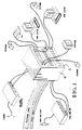
- the cable management system with which the present invention is concerned is contained within an enclosure 10 illustrated as having media-specific connectors on both its front surface 12 and its rear surface (not shown).
- the cable management system within the enclosure 10 serves as a flexible electronic patching, or cross-connecting, hub for automated cable management of communications circuits.
- Various services such as LAN'S, telephone, computer I/O channels and peripherals, and video distribution links are connected to the cable management system through media-specific connectors on the rear surface of the enclosure 10.
- these will be aggregated multi-pair cables or high bandwidth cables, such as coax and fiber, common in riser and horizontal distribution subsystems.
- such services include ethernet, telephone, video and token ring.
- Matrix switch modules are installed within the enclosure 10.
- Media-specific connectors corresponding to the media selected for each user's work station subsystem wiring are installed on the front surface 12 and have cables which are attached and then run to the user's location.
- at the user's location there may be one or more telephones, computer work stations, facsimile machines, or television sets. Once wired in this fashion, each user can be electronically connected to any combination of services that is required. All future changes in each user's service complement can be accomplished electronically.
- the cable management system within the enclosure 10 maintains a data base of the location, source and destination for each cable.
- the system is configured by a management station 14 (FIG. 2).
- the cable management system contained within the enclosure 10 is connected to the service lines 16, which may be telephone lines, video lines, etc., which come to the system from the various service providers.
- the cable management system is also connected to the user lines 18 which extend to various user locations.
- the user lines 18 are each connected to a respective port on one of a plurality of line termination unit circuit cards 20-1,..., 20-n.
- the service lines 16 are each connected to a respective port on one of a plurality of service termination unit circuit cards 22-1, ... , 22-p.
- the switching matrix for connecting the service lines 16 to the user lines 18 is distributed among the service termination unit circuit cards 22-1,..., 22-p so that each of the service termination unit circuit cards 22-1,..., 22-p includes thereon a plurality of service termination units for connection to a group of the service lines 16 and a portion of the overall switch matrix.
- the line termination unit circuit cards 20-1,..., 20-n and the service termination unit circuit cards 22-1,..., 22-p are installed on opposite sides of a centerplane board 24, represented schematically in FIG.
- every line termination unit circuit card 20-1,..., 20-n is connected to the switch matrix portion of every service termination unit circuit card 22-1,..., 22-p, as will be described in full detail hereinafter.
- a controller circuit card 26 which is mounted to the centerplane board 24 on the same side thereof as the service termination unit circuit cards 22-1,..., 22-p.
- the controller circuit card 26 is connected to the management station 14 in a suitable manner, such as through an RS-232 link or a modem.
- a multi-line communications bus 38 (FIG. 3C) is provided on the centerplane board 24.
- Each of the controller circuit card 26, the line termination unit circuit cards 20-1,..., 20-n, and the service termination unit circuit cards 22-1,..., 22-p, is provided with a respective transceiver 28, 30 and 32 which is coupled to the communications bus 38 when the respective circuit card is mounted to the centerplane board 24.
- Each of the service termination unit circuit cards 22-1,..., 22-p includes a memory which contains a map of all the connections through the switch matrix portion on the respective service termination unit circuit card
- the controller circuit card 26 includes a memory which contains a map of all of the connections in the entire cable management system within the enclosure 10.
- the management station 14 issues commands to the circuitry on the controller circuit card 26. These commands include a connect command to make a connection between one or more specified service lines 16 and one or more specified user lines 18, and a disconnect command to open a connection between a specified one of the service lines 16 and a specified one of the user lines 18.
- the circuitry on the controller circuit card 26 places each appropriate command onto the communications bus 38 on the centerplane board 24, from which it is received by the transceiver 32 on the specified one of the service termination unit circuit cards 22-1,..., 22-p, which then controls its respective switch matrix portion in accordance with the received command to either make or open the specified connection.
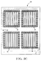
- FIG. 3A there are illustratively sixteen service termination unit circuit cards 22-1,..., 22-16 which are installed vertically in the enclosure 10 from the rear thereof.
- the controller circuit card 26 which is comprised of two half-cards 26-1 and 26-2, is also installed vertically, as is a line test card 34, the function of which will be described hereinafter as it pertains to an illustrative embodiment of this invention.
- FIG. 3B there are illustratively sixteen line termination unit circuit cards 20-1,..., 20-16 which are installed horizontally in the enclosure 10 from the front thereof.
- Each of the line termination unit circuit cards 20-1,..., 20-16 and the service termination unit circuit cards 22-1,..., 22-16 has eight ports terminated by a respective media-specific connector on the visible edge of the circuit card away from the centerplane board 24 for connection to a respective user or service line.
- each of the line termination unit circuit cards 20-1,...20-16 and the service termination unit circuit cards 22-1,..., 22-16 has a ninth port connector used for the testing function, as will be described hereinafter.
- FIGS. 3C and 3D illustrate opposite sides of the centerplane board 24.
- FIG. 3C shows the side of the centerplane board 24 on which the service termination unit circuit cards, the controller circuit cards, and the line test card are mounted
- FIG. 3D shows the side of the centerplane board 24 on which the line termination unit circuit cards are mounted.
- the controller circuit cards and the line test card there is provided a pair of vertically oriented card edge connectors 36.
- FIG. 3D on the other side of the centerplane board 24 there is provided for each of the line termination unit circuit cards a pair of horizontally oriented card edge connectors 36.
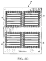
- Each of the card edge connectors 36 has within it nine fields, each of which includes thirty six pins 37 (FIG. 3E) arranged in a square 6x6 matrix. The pins extend through the centerplane board 24 to a corresponding field in one of the card edge connectors 36 on the other side of the board 24, thereby interconnecting the connectors 36 on both sides of the board 24.
- each of the service termination unit circuit cards 22-1,..., 22-16 and the line termination unit circuit cards 20-1,..., 20-16 has eight input/output ports.
- each of the four wires of a service termination unit circuit card port is connected to the switch matrix portion on that service termination unit circuit card.
- each service termination unit circuit card's switch matrix portion are eight 4-wire bundles which are each connected to four pins of each of sixteen of the pin fields of the connector 36 associated with that service termination unit circuit card. Again, that accounts for thirty two of the thirty six pins in each of those sixteen pin fields, with the remaining four pins being reserved for the same power, ground and control signals.
- FIG. 3E illustrates how the line termination unit circuit card 20-1 is connected to a pin field of the service termination unit circuit card 22-16, as well as to all corresponding pin fields of all the other fifteen service termination unit circuit cards.
- the pins 37 (a square 6x6 array) connect the card edge connectors 36 on the two sides of the centerplane board 24 at their intersections (i.e., at their common pin fields).
- the line termination unit circuit cards 20-1,..., 20-16 take up the second through the seventeenth rows of the horizontal connectors 36 on their side of the centerplane board 24. The top and bottom rows are vacant.
- the service termination unit circuit cards 22-1,..., 22-16 take up the third through the eighteenth columns of the vertical connectors 36 on their side of the board 24.
- any one of the service lines 16 can be connected to any one of the user lines 18.
- Each switch matrix portion on a service termination unit circuit card is an eight port by 128 port (32 by 512 lines) matrix of crosspoints.
- each of the 128 service lines can be connected to each of the 128 user ports.
- the bus 38 extends parallel to the leftmost column of the vertical connectors 36 and parallel to the upper row of the horizontal connectors 36 (not shown in FIG. 3C) on the other side of the board 24.
- the bus 38 is terminated at the pin fields in the second through seventeenth rows of the leftmost column for connection to the transceivers 30 on all of the line termination unit circuit cards 20-1,..., 20-16; at the upper pin fields in the second through eighteenth columns for connection to the transceiver on the line test card 34 and to the transceivers 32 on all of the service termination unit circuit cards 22-1,..., 22-16; and at the upper pin field of the first column for connection to the transceiver 28 on the controller circuit card 26.
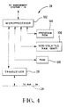
- FIG. 4 illustrates circuitry on the controller circuit card 26 which may be utilized in the cable management system with which the present invention is concerned.
- the controller 26 includes a microprocessor 102 which is associated with three different types of memory.
- the first type of memory is a program read only memory (ROM) 104 which has stored therein the program instructions for operating the microprocessor 102.
- the microprocessor 102 is also associated with a random access memory (RAM) 106 which is utilized as a temporary storage memory by the microprocessor 102.
- RAM random access memory
- non-volatile random access memory 108 which is utilized to store a map showing all of the connections through the switch matrix portions on the service termination unit circuit cards 22-1,..., 22-16 as well as information as to what type of card is installed in each of the connectors 36.
- the non-volatile RAM 108 may be an electrically erasable PROM or a "flash" PROM which saves its contents even when power is lost. Since it takes a relatively long time to write information into the non-volatile RAM 108, the RAM 106 is used to temporarily store the map until such time as it is written into the non-volatile RAM 108.
- the microprocessor 102 is coupled to the management station 14 in any suitable manner, such as by an RS-232 link or a modem, or through a local area network.
- the microprocessor 102 receives commands from the management station 14, such as a connect command or a disconnect command as described above, and in accordance with the program stored in the ROM 104 transmits instructions over the bus lines 38 on the centerplane board 24 via the transceiver 28.
- the transceiver 28 is a Neuron chip manufactured by Echelon Corp.
- the microprocessor 102 addresses a specified one of the service termination unit circuit cards 22-1,..., 22-16 over the bus 38 via the transceiver 28 and provides an appropriate instruction for controlling the switch matrix portion of that service termination unit circuit card.
- the microprocessor 102 receives acknowledgements of its instructions, which are returned over the bus 38 from the specified service termination unit circuit card, via the transceiver 28, and updates the map stored in the non-volatile RAM 108.
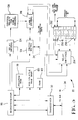
- FIG. 5 illustrates the circuitry 22 on one of the service termination unit circuit cards 22-1,..., 22-16.
- This circuitry includes a microprocessor 116 having associated therewith three types of memory.
- These memories function similarly to the memories 104, 108 and 106, respectively, associated with the microprocessor 102 of the controller 26, but are specifically for the particular one of the service termination unit circuit cards 22-1,..., 22-16 with which they are associated.
- the microprocessor 116 is coupled to the transceiver 32, which is illustratively a Neuron chip manufactured by Echelon Corp.
- the transceiver 32 is coupled to the bus lines 38 on the centerplane board 24 and is utilized for communications between the microprocessor 116 and the microprocessor 102 on the controller circuit card 26. Instructions received by the microprocessor 116 via the transceiver 32 over the bus 38 from the microprocessor 102 are utilized to control the relay drivers 124 and the switch matrix 126. Interfacing between the service lines 16 and the switch matrix 126 is effected via service line circuit paths which include the cable drivers (amplifiers) 130. The relay drivers 124 set the control relays 128 so that the cable drivers 130 interposed between the service lines 16 and the switch matrix 126 are "pointing" in the proper directions. At system start-up, for safety reasons the cable drivers 130 are initially bypassed.
- the switch matrix 126 is connected to all of the line termination unit circuit cards 20-1,..., 20-16 mounted on the other side of the centerplane board 24, as previously described, so that any one of the service lines 16 entering that particular service termination unit circuit card may be connected to any one of the user lines 18.
- the microprocessor 116 controls the switch matrix 126 to make an appropriate physical electrical connection therethrough between a specified one of the service lines 16 entering that card and a specified one of the user lines 18 entering any one of the line termination unit circuit cards 20-1,..., 20-16 on the other side of the centerplane board 24.
- the line termination unit circuit card 20 illustrated in FIG. 6 includes the transceiver 30 coupled to the bus lines 38 on the centerplane board 24.
- the transceiver 30 is a Neuron® chip manufactured by Echelon Corp.
- the function of the line termination unit circuit card 20 is to provide interfaces between the user lines 18 and the switch matrices on the service termination unit circuit cards 22-1,..., 22-16 mounted on the other side of the centerplane board 24. This interfacing takes place via user line circuit paths which include the cable drivers (amplifiers) 110.
- the cable drivers 110 are selectively controllable to pass signals either from individual ones of the service lines 16 to individual ones of the user lines 18 or in the reverse direction from individual ones of the user lines 18 to individual ones of the service lines 16, as determined by the settings of respective ones of the control relays 112.
- the control relays 112 are controlled by the relay drivers 114 which are operated on the basis of instructions received via the transceiver 30 from the microprocessor 102 of the controller 26 over the bus lines 38 on the centerplane board 24. Initially, all the cable drivers 110 are set to pass signals in the direction from the user lines 18 to the service lines 16, with the cable drivers being bypassed. This is for safety reasons so that upon system start-up dangerously high amplified signals are not inadvertently transmitted to the user lines 18, where they could damage sensitive equipment.
- the equipment for testing the user lines 18 and the service lines 16 can either be incorporated in an enclosure separate from the enclosure 10 (e.g., as a handheld unit) or be permanently installed within the enclosure 10.
- the line testing equipment is illustratively similar to the MT350 Scanner manufactured by MicroTest of Phoenix, Arizona.
- MT350 Scanner manufactured by MicroTest of Phoenix, Arizona.
- This patent discloses a handheld unit, which may be modified for mounting on a circuit card when permanently installed within the enclosure 10.
- the tester disclosed in the referenced patent is capable of selectively evaluating various characteristics of a line connected to its output port.
- the tester can determine the length of a line, its capacitance and its resistance. It can also evaluate the near end crosstalk of a line, its attenuation characteristics at various frequencies and the noise on a line within various frequency bands. Further, the tester can also be controlled to automatically run a combination of these tests.
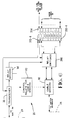
- each of the line termination unit circuit cards 20 in addition to having eight user line port connectors 202-1,..., 202-8, has a test port connector 204 for receiving a connection to the tester.
- a bank of switches 206 In order to be able to connect a selected one of the user lines 18 to the line tester, there is provided a bank of switches 206.
- the switches 206 are connected to the user line port connectors 202-1,..., 202-8, the test port connector 204 and the cable drivers 110.
- each "line” includes a number of wires, illustratively four.
- the bank of switches 206 includes a plurality of individual switches 208 each having an armature 210.
- the armatures 210 are each controlled by a relay coil (not shown) which is selectively energized by the relay drivers 114 (FIG. 6) which are operated on the basis of instructions received from the transceiver 30, as will be described hereinafter. As shown in FIG. 8, with the armatures 210 in the position shown by the solid line, each of the user line port connectors 202-1,..., 202-8, is connected to a respective one of the cable drivers 110. When an armature 210 is in the position shown by the broken line, the user line port connector associated with that particular one of the switches 208 is connected to the test port connector 204 so that the particular user line can be evaluated.
- a bank of switches 254 In order to be able to connect a selected one of the service lines 16 to the line tester, there is provided a bank of switches 254.
- the switches 254 are connected to the service line port connectors 250-1,..., 250-8, the test port connector 252 and the cable drivers 130.
- each "line” includes a number of wires, illustratively four.
- the bank of switches 254 includes a plurality of individual switches 256 each having an armature 258.
- the armatures 258 are each controlled by a relay coil (not shown) which is selectively energized by the relay drivers 124 (FIG. 5) which are operated on the basis of instructions received from the transceiver 32, as will be described hereinafter.
- the relay drivers 124 FIG. 5
- each of the service line port connectors 250-1,..., 250-8 is connected to a respective one of the cable drivers 130.
- the service line port connector associated with that particular one of the switches 256 is connected to the test port connector 252 so that the particular service line can be evaluated.
- the technician When the line tester is a handheld unit, as disclosed in the referenced patent, and a technician wishes to evaluate a particular one of the user lines 18 or the service lines 16, the technician connects the line tester, via a cable, to the test port connector 204 or 252 on that one of the line termination unit circuit cards 20 or the service termination unit circuit cards 22 to which the line being evaluated is connected.
- the technician communicates with the controller 26 via the transceiver 30 or 32 and the bus 38, to cause the controller 26 to send an instruction to open all connections through the switch matrix 126 to the particular one of the lines 18 or 16 which is to be evaluated.
- the service provider is notified (e.g., by a telephone call) so that no signals are applied to the service line which would interfere with the testing.
- the technician then sends a command through the transceiver 30 or 32 to the relay drivers 114 or 124 to cause the particular one of the switches 208 or 256 which is associated with the line port connector associated with the particular line to move its armature 210 or 258 so that that line port connector is connected to the test port connector 204 or 252.
- the evaluation results are transmitted to the controller 26 via the transceiver 30 or 32 and the bus 38.
- the particular switch 208 or 256 associated with that line is then caused to move its armature 210 or 258 so that the line port connector 202 or 250 is connected to one of the cable drivers 110 or 130, and then any desired connection through the switch matrix 126 may be effected.
- the line tester may be permanently installed within the enclosure 10.
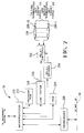
- the line tester is illustratively mounted to the line test card 34 as shown in FIG. 7.
- the line test card 34 includes a microprocessor 220 having associated therewith a program ROM 222 and a RAM 224.
- the memories 222 and 224 function similarly to the memories 104, 106, respectively, associated with the microprocessor 102 of the controller 26, but are specifically for the line test card 34.
- the microprocessor 220 is coupled to the transceiver 226, which is illustratively a Neuron chip manufactured by Echelon Corp.
- the transceiver 226 is coupled to the bus lines 38 on the centerplane board 24 and is utilized for communications between the microprocessor 220 and the other circuit cards in the enclosure 10. Also mounted on the line test card 34 is a line tester 228, which is substantially identical, at least as far as its circuitry is concerned, with the tester disclosed in the referenced patent, but is modified for mounting on the line test card 34 rather than within a handheld enclosure.
- the line tester 228 is controlled by the microprocessor 220 in accordance with instructions received from the management station 14, to which it is coupled in any suitable manner, such as by an RS-232 link or a modem, or through a local area network.
- the line tester 228 has its output port 230 connected to the bank of relay switches 232, which are controlled from the microprocessor 220 through the relay drivers 234.
- the relay switches 232 are arranged similarly to the switches 206 shown in FIG. 8 and the switches 254 shown in FIG. 9. However, there are illustratively thirty two individual switches within the switch bank 232, each of which corresponds to a respective one of the line termination units circuit cards 20-1,...20-16 and the service termination unit circuit cards 22-1,..., 22-16.
- Each of the switches within the switch bank 232 is connected to a respective test port connector 204, 252 on a respective line or service termination unit circuit card by one of the test cables 236-1,..., 236-32 which are each connected to a respective connection port 238 on the line test card 34. So that there are no disparities when testing the user lines, all of the test cables 236 are substantially identical, at least as to length and gauge.
- the system operator at the management station 14 sends a command to the controller 26 to disconnect the selected line from any other line to which it had been connected. If a service line is being tested, the service provider is notified, as discussed above.
- the management station 14 then causes the microprocessor 220 on the line test card 34 to control the appropriate one of the relay drivers 234 to actuate the appropriate one of the switches 232 so that the line tester 228 is connected to the appropriate one of the termination unit circuit cards 20, 22.
- the microprocessor 220 also sends a command via the transceiver 226 and the bus 38 to the transceiver 30 or 32 on that termination unit circuit card to actuate the appropriate one of the switches 206 or 254 to connect the test port connector 204 or 252 to the appropriate one of the line port connectors 202 or 250 associated with the selected user or service line. After that line is evaluated, the line tester 228 transmits the evaluation results to the microprocessor 220 for transmission to the management station 14.
- testing of the lines can be done upon initial system installation to develop an "as built" data base of user line characteristics.
- each of the termination unit circuit cards 20 and 22 has been shown (FIGS. 5 and 6). These embodiments are specifically for the case where the line tester is separate from the cable management system and must communicate directly with the controller 26.
- the wires between the test port connector 204 or 252 and the transceiver 30 or 32 on the termination unit circuit card 20 or 22 may be eliminated or, for uniformity of card manufacture, may remain but are not utilized.
Landscapes
- Engineering & Computer Science (AREA)
- Computer Networks & Wireless Communication (AREA)
- Signal Processing (AREA)
- Physics & Mathematics (AREA)
- Mathematical Physics (AREA)
- Computer Security & Cryptography (AREA)
- Structure Of Telephone Exchanges (AREA)
- Maintenance And Management Of Digital Transmission (AREA)
- Monitoring And Testing Of Exchanges (AREA)
Applications Claiming Priority (4)
| Application Number | Priority Date | Filing Date | Title |
|---|---|---|---|
| US296947 | 1981-08-28 | ||
| US15617993A | 1993-11-22 | 1993-11-22 | |
| US156179 | 1993-11-22 | ||
| US29694794A | 1994-08-26 | 1994-08-26 |
Publications (2)
| Publication Number | Publication Date |
|---|---|
| EP0654674A2 true EP0654674A2 (de) | 1995-05-24 |
| EP0654674A3 EP0654674A3 (de) | 1995-09-13 |
Family
ID=26852937
Family Applications (1)
| Application Number | Title | Priority Date | Filing Date |
|---|---|---|---|
| EP94308514A Withdrawn EP0654674A3 (de) | 1993-11-22 | 1994-11-17 | Kabelverteilersystem mit Prüfung von Versorgungs- und Teilnehmeranschlussleitungen. |
Country Status (7)
| Country | Link |
|---|---|
| EP (1) | EP0654674A3 (de) |
| KR (1) | KR950016091A (de) |
| CN (1) | CN1115926A (de) |
| BR (1) | BR9404670A (de) |
| CA (1) | CA2134918A1 (de) |
| HU (1) | HUT71565A (de) |
| PL (1) | PL305865A1 (de) |
Cited By (3)
| Publication number | Priority date | Publication date | Assignee | Title |
|---|---|---|---|---|
| NL1001776C2 (nl) * | 1995-11-29 | 1997-05-30 | Nederland Ptt | Inrichting voor het verrichten van metingen aan communicatieleidingen. |
| EP0827357A3 (de) * | 1996-08-26 | 1998-11-25 | Nec Corporation | Netzwerkknoten zur Querverbindung |
| KR20000025232A (ko) * | 1998-10-09 | 2000-05-06 | 김영환 | Cdma 시스템에서 다중 드라이버/리시버 지원 ber 테스트보드 |
Family Cites Families (1)
| Publication number | Priority date | Publication date | Assignee | Title |
|---|---|---|---|---|
| US4845736A (en) * | 1988-04-19 | 1989-07-04 | Pacific Bell | Cross-connect switch and method for providing test access thereto |
-
1994
- 1994-11-02 CA CA002134918A patent/CA2134918A1/en not_active Abandoned
- 1994-11-16 PL PL94305865A patent/PL305865A1/xx unknown
- 1994-11-16 HU HU9403286A patent/HUT71565A/hu unknown
- 1994-11-17 EP EP94308514A patent/EP0654674A3/de not_active Withdrawn
- 1994-11-21 CN CN94118906A patent/CN1115926A/zh active Pending
- 1994-11-21 KR KR1019940030561A patent/KR950016091A/ko not_active Withdrawn
- 1994-11-21 BR BR9404670A patent/BR9404670A/pt not_active Application Discontinuation
Cited By (4)
| Publication number | Priority date | Publication date | Assignee | Title |
|---|---|---|---|---|
| NL1001776C2 (nl) * | 1995-11-29 | 1997-05-30 | Nederland Ptt | Inrichting voor het verrichten van metingen aan communicatieleidingen. |
| WO1997020223A1 (en) * | 1995-11-29 | 1997-06-05 | Koninklijke Ptt Nederland N.V. | Device for carrying out measurements on communication lines |
| EP0827357A3 (de) * | 1996-08-26 | 1998-11-25 | Nec Corporation | Netzwerkknoten zur Querverbindung |
| KR20000025232A (ko) * | 1998-10-09 | 2000-05-06 | 김영환 | Cdma 시스템에서 다중 드라이버/리시버 지원 ber 테스트보드 |
Also Published As
| Publication number | Publication date |
|---|---|
| EP0654674A3 (de) | 1995-09-13 |
| KR950016091A (ko) | 1995-06-17 |
| CN1115926A (zh) | 1996-01-31 |
| BR9404670A (pt) | 1995-07-11 |
| CA2134918A1 (en) | 1995-05-23 |
| PL305865A1 (en) | 1995-05-29 |
| HU9403286D0 (en) | 1995-01-30 |
| HUT71565A (en) | 1995-12-28 |
Similar Documents
| Publication | Publication Date | Title |
|---|---|---|
| US5541586A (en) | Visual outlet identification in a cable management system | |
| US5432505A (en) | Cable management system with automatic mapping | |
| US5523747A (en) | Asset management in a cable management system | |
| US5375159A (en) | System and method for remote testing and protocol analysis of communication lines | |
| US5515037A (en) | Wire selection in a cable management system | |
| DE69433568T2 (de) | Verfahren und System zur Verbindung eines optischen Netzes mit einer Mehrzahl von Teilnehmergruppen | |
| EP0624043A1 (de) | Kabelverwaltungssystem | |
| US4670626A (en) | Cross connect frame for digital signals | |
| EP0654674A2 (de) | Kabelverteilersystem mit Prüfung von Versorgungs- und Teilnehmeranschlussleitungen | |
| WO1995027379A1 (en) | Cable management system with remote line testing | |
| EP0657741A2 (de) | Kabelmanagementsystem mit Ferntest der Leitungen mittels Schalter | |
| JP2005535158A (ja) | 測定装置および電気通信アセンブリ | |
| US7746983B2 (en) | Distributor with a test access | |
| CA1251584A (en) | Digital signal cross-connection system | |
| EP0660622A2 (de) | Vermittlung von symmetrischen Leitungspaaren in einem Kabelverwaltungssystem mit einer verminderten Anzahl von Koppelpunkten | |
| US6535602B1 (en) | Telecommunications wiring device | |
| SA07280060B1 (ar) | جهاز دخول وطريقه لاختبار خط المشترك الرقمى | |
| CZ280094A3 (en) | Device for controlling cable network with testing order-wire and subscriber's circuits | |
| CZ210795A3 (en) | Apparatus for controlling a cable network with testing an order-wire circuit and subscriber's line user- | |
| US20080260140A1 (en) | Method and System for Scanning and Detecting Metallic Cross-Connects | |
| KR940027614A (ko) | 케이블 관리 시스템 | |
| JPH04237293A (ja) | 配線モジュールおよびその配線方法およびその試験方法 |
Legal Events
| Date | Code | Title | Description |
|---|---|---|---|
| PUAI | Public reference made under article 153(3) epc to a published international application that has entered the european phase |
Free format text: ORIGINAL CODE: 0009012 |
|
| AK | Designated contracting states |
Kind code of ref document: A2 Designated state(s): DE FR GB IT |
|
| PUAL | Search report despatched |
Free format text: ORIGINAL CODE: 0009013 |
|
| AK | Designated contracting states |
Kind code of ref document: A3 Designated state(s): DE FR GB IT |
|
| STAA | Information on the status of an ep patent application or granted ep patent |
Free format text: STATUS: THE APPLICATION IS DEEMED TO BE WITHDRAWN |
|
| 18D | Application deemed to be withdrawn |
Effective date: 19960314 |