EP0654675A1 - Apparat und Verfahren mittels magnetischer Resonanz - Google Patents
Apparat und Verfahren mittels magnetischer Resonanz Download PDFInfo
- Publication number
- EP0654675A1 EP0654675A1 EP94307885A EP94307885A EP0654675A1 EP 0654675 A1 EP0654675 A1 EP 0654675A1 EP 94307885 A EP94307885 A EP 94307885A EP 94307885 A EP94307885 A EP 94307885A EP 0654675 A1 EP0654675 A1 EP 0654675A1
- Authority
- EP
- European Patent Office
- Prior art keywords
- slice
- patient
- magnetic resonance
- gradient
- imaging
- Prior art date
- Legal status (The legal status is an assumption and is not a legal conclusion. Google has not performed a legal analysis and makes no representation as to the accuracy of the status listed.)
- Granted
Links
Images


Classifications
-
- G—PHYSICS
- G01—MEASURING; TESTING
- G01R—MEASURING ELECTRIC VARIABLES; MEASURING MAGNETIC VARIABLES
- G01R33/00—Arrangements or instruments for measuring magnetic variables
- G01R33/20—Arrangements or instruments for measuring magnetic variables involving magnetic resonance
- G01R33/44—Arrangements or instruments for measuring magnetic variables involving magnetic resonance using nuclear magnetic resonance [NMR]
- G01R33/48—NMR imaging systems
- G01R33/54—Signal processing systems, e.g. using pulse sequences ; Generation or control of pulse sequences; Operator console
- G01R33/56—Image enhancement or correction, e.g. subtraction or averaging techniques, e.g. improvement of signal-to-noise ratio and resolution
- G01R33/563—Image enhancement or correction, e.g. subtraction or averaging techniques, e.g. improvement of signal-to-noise ratio and resolution of moving material, e.g. flow contrast angiography
- G01R33/56375—Intentional motion of the sample during MR, e.g. moving table imaging
-
- A—HUMAN NECESSITIES
- A61—MEDICAL OR VETERINARY SCIENCE; HYGIENE
- A61B—DIAGNOSIS; SURGERY; IDENTIFICATION
- A61B5/00—Measuring for diagnostic purposes; Identification of persons
- A61B5/05—Detecting, measuring or recording for diagnosis by means of electric currents or magnetic fields; Measuring using microwaves or radio waves
- A61B5/055—Detecting, measuring or recording for diagnosis by means of electric currents or magnetic fields; Measuring using microwaves or radio waves involving electronic [EMR] or nuclear [NMR] magnetic resonance, e.g. magnetic resonance imaging
-
- A—HUMAN NECESSITIES
- A61—MEDICAL OR VETERINARY SCIENCE; HYGIENE
- A61B—DIAGNOSIS; SURGERY; IDENTIFICATION
- A61B5/00—Measuring for diagnostic purposes; Identification of persons
- A61B5/70—Means for positioning the patient in relation to the detecting, measuring or recording means
- A61B5/704—Tables
-
- G—PHYSICS
- G01—MEASURING; TESTING
- G01R—MEASURING ELECTRIC VARIABLES; MEASURING MAGNETIC VARIABLES
- G01R33/00—Arrangements or instruments for measuring magnetic variables
- G01R33/20—Arrangements or instruments for measuring magnetic variables involving magnetic resonance
- G01R33/28—Details of apparatus provided for in groups G01R33/44 - G01R33/64
-
- G—PHYSICS
- G01—MEASURING; TESTING
- G01R—MEASURING ELECTRIC VARIABLES; MEASURING MAGNETIC VARIABLES
- G01R33/00—Arrangements or instruments for measuring magnetic variables
- G01R33/20—Arrangements or instruments for measuring magnetic variables involving magnetic resonance
- G01R33/44—Arrangements or instruments for measuring magnetic variables involving magnetic resonance using nuclear magnetic resonance [NMR]
- G01R33/48—NMR imaging systems
- G01R33/4818—MR characterised by data acquisition along a specific k-space trajectory or by the temporal order of k-space coverage, e.g. centric or segmented coverage of k-space
- G01R33/4824—MR characterised by data acquisition along a specific k-space trajectory or by the temporal order of k-space coverage, e.g. centric or segmented coverage of k-space using a non-Cartesian trajectory
-
- G—PHYSICS
- G01—MEASURING; TESTING
- G01R—MEASURING ELECTRIC VARIABLES; MEASURING MAGNETIC VARIABLES
- G01R33/00—Arrangements or instruments for measuring magnetic variables
- G01R33/20—Arrangements or instruments for measuring magnetic variables involving magnetic resonance
- G01R33/44—Arrangements or instruments for measuring magnetic variables involving magnetic resonance using nuclear magnetic resonance [NMR]
- G01R33/48—NMR imaging systems
- G01R33/54—Signal processing systems, e.g. using pulse sequences ; Generation or control of pulse sequences; Operator console
- G01R33/56—Image enhancement or correction, e.g. subtraction or averaging techniques, e.g. improvement of signal-to-noise ratio and resolution
- G01R33/563—Image enhancement or correction, e.g. subtraction or averaging techniques, e.g. improvement of signal-to-noise ratio and resolution of moving material, e.g. flow contrast angiography
- G01R33/56308—Characterization of motion or flow; Dynamic imaging
-
- G—PHYSICS
- G01—MEASURING; TESTING
- G01R—MEASURING ELECTRIC VARIABLES; MEASURING MAGNETIC VARIABLES
- G01R33/00—Arrangements or instruments for measuring magnetic variables
- G01R33/20—Arrangements or instruments for measuring magnetic variables involving magnetic resonance
- G01R33/28—Details of apparatus provided for in groups G01R33/44 - G01R33/64
- G01R33/38—Systems for generation, homogenisation or stabilisation of the main or gradient magnetic field
- G01R33/381—Systems for generation, homogenisation or stabilisation of the main or gradient magnetic field using electromagnets
- G01R33/3815—Systems for generation, homogenisation or stabilisation of the main or gradient magnetic field using electromagnets with superconducting coils, e.g. power supply therefor
-
- G—PHYSICS
- G01—MEASURING; TESTING
- G01R—MEASURING ELECTRIC VARIABLES; MEASURING MAGNETIC VARIABLES
- G01R33/00—Arrangements or instruments for measuring magnetic variables
- G01R33/20—Arrangements or instruments for measuring magnetic variables involving magnetic resonance
- G01R33/44—Arrangements or instruments for measuring magnetic variables involving magnetic resonance using nuclear magnetic resonance [NMR]
- G01R33/48—NMR imaging systems
- G01R33/54—Signal processing systems, e.g. using pulse sequences ; Generation or control of pulse sequences; Operator console
- G01R33/56—Image enhancement or correction, e.g. subtraction or averaging techniques, e.g. improvement of signal-to-noise ratio and resolution
- G01R33/563—Image enhancement or correction, e.g. subtraction or averaging techniques, e.g. improvement of signal-to-noise ratio and resolution of moving material, e.g. flow contrast angiography
- G01R33/56375—Intentional motion of the sample during MR, e.g. moving table imaging
- G01R33/56383—Intentional motion of the sample during MR, e.g. moving table imaging involving motion of the sample as a whole, e.g. multistation MR or MR with continuous table motion
-
- G—PHYSICS
- G01—MEASURING; TESTING
- G01R—MEASURING ELECTRIC VARIABLES; MEASURING MAGNETIC VARIABLES
- G01R33/00—Arrangements or instruments for measuring magnetic variables
- G01R33/20—Arrangements or instruments for measuring magnetic variables involving magnetic resonance
- G01R33/44—Arrangements or instruments for measuring magnetic variables involving magnetic resonance using nuclear magnetic resonance [NMR]
- G01R33/48—NMR imaging systems
- G01R33/54—Signal processing systems, e.g. using pulse sequences ; Generation or control of pulse sequences; Operator console
- G01R33/56—Image enhancement or correction, e.g. subtraction or averaging techniques, e.g. improvement of signal-to-noise ratio and resolution
- G01R33/565—Correction of image distortions, e.g. due to magnetic field inhomogeneities
- G01R33/56509—Correction of image distortions, e.g. due to magnetic field inhomogeneities due to motion, displacement or flow, e.g. gradient moment nulling
Definitions
- This invention relates to the magnetic resonance apparatus and methods. It finds particular application in conjunction with magnetic resonance diagnostic imaging apparatus and methods and will be described with particular reference thereto.
- the imaging volume is generally limited to a sphere within which the primary magnetic field is temporally invariant and uniform.
- Prior art magnetic resonance imaging systems typically have required a magnetic assembly with a patient receiving bore that is at least 1.5 meters long in order to provide a uniform imaging volume of about 40 cm in diameter.
- One disadvantage of these systems is that very large magnets and magnet assemblies are required. These very large magnet assemblies have several drawbacks including their large size, immense weight, and high cost. Not only are the magnets themselves expensive, but so is the large size related equipment for generating gradient magnetic fields, RF pulses, and the like.
- spiral CT scanners are not only much less expensive than conventional magnetic resonance equipment, but also enable the imaging volume to be greatly elongated.
- spiral CT scanners have several other drawbacks.
- the data is collected along spirals which tends to skew the slices, introduce partial volume artifacts, and otherwise degrade the resultant image data.
- magnetic resonance is preferable for distinguishing many types of tissue, particularly soft tissue and blood.
- Spiral CT scans to image the patient's circulatory system commonly require the infusion of a contrast agent into the blood. The contrast agent, which has good x-ray stopping power, is then imaged rather than the blood itself.
- the present invention contemplates a new and improved magnetic resonance apparatus and method which enables a larger volume to be imaged with simpler, less-expensive equipment.
- a magnetic resonance apparatus comprising: a patient receiving region; a main magnetic field means disposed around the patient receiving region for generating a main magnetic field which is uniform and temporally constant within an examination volume in the patient receiving region; a radio frequency coil disposed around the examination volume; and a patient support and transport means for supporting a patient in the examination volume during a magnetic resonance examination; characterised in that the examination volume is thin in a direction parallel to the axis of the patient receiving region; and the patient support and transport means moves the patient axially through the examination volume during a magnetic resonance examination.
- the apparatus further includes a gradient coil assembly disposed around the radio frequency coil for creating gradient magnetic fields along orthogonal directions in the examination volume.
- the patient receiving region is cylindrical and the examination volume is a cylinder at least 45 cm in diameter and less than 15 cm thick.
- the invention also provides a method of magnetic resonance imaging comprising: creating a uniform, temporally constant magnetic field in a thin imaging volume; moving a subject through the thin imaging volume; while the subject is moving through the imaging volume, exciting and manipulating magnetic resonance in a selected slice of the subject that is in the imging volume and receiving magnetic resonance signals from the selected slice, the imaging volume having a thickness of at least twice the selected slice thickness and less than 15cm in the direction of moving the subject; and reconstructing the magnetic resonance signals from a plurality of slices into an image representation.
- the step of exciting and manipulating magnetic resonance and receiving magnetic resonance signals from the selected slice includes applying a slice select gradient along the direction of moving the subject and the method further includes shifting the selected slice relative to the imaging volume such that the selected slice remains substantially fixed relative to the subject.
- the selected slice shifting step suitably comprises incrementing a frequency of the received resonance signals.
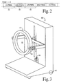
- the apparatus includes a gantry A which is operated by an electronic processing and control circuit B to excite and manipulate magnetic resonance in a thin imaging volume 10 that is only 2-20 slices thick.
- the processing and control circuit processes resultant resonance signals from the imaging volume into image representations.
- a patient transport assembly C moves a patient through the imaging volume during the imaging process.
- a main magnet assembly 12 preferably a self-shielded superconducting magnet assembly, generates a primary magnetic field which is temporally constant and uniform in the thin imaging volume 10 .
- the imaging volume 10 is a thin disk, about 45 cm or more in diameter, transverse to the longitudinal direction.
- the thin volume 10 is sufficiently wide that about 10-20 parallel slices can be generated within the imaging volume 10 . This enables the scanner to be used for brain scans and obtain traditional volume image representations representing about a 15 cm thick slab through the brain without moving the patient.
- an imaging volume 10 which is twice the thickness of the maximum available slice is satisfactory.
- a width of two slices is sufficient to image an indefinite length of the patient when the patient is being moved continuously through the examination region.
- a main magnetic field control means 14 controls the main magnet assembly 12 .
- the magnetic field control 14 is used to ramp up the magnetic field.
- the main magnetic field control 14 not only turns on and turns off the main magnet, but also maintains a uniform current flow.
- a radio frequency coil 20 surrounds the imaging volume 10 .
- the RF coil is preferably relatively narrow in the longitudinal direction and shaped for (1) transmitting magnetic field signals substantially exclusively into the imaging volume 10 and (2) receiving radio frequency signals substantially exclusively from the imaging volume.
- a radio frequency shield surrounds the RF coil 20 to prevent radio frequency signals from being irradiated radially outward and to render the radio frequency coil more insensitive to radio frequency signals from outside the imaging volume.
- a radio frequency transmitter 22 selectively supplies radio frequency current pulses to the radio frequency coil to cause radio frequency pulses to be transmitted into the volume region for exciting and manipulating magnetic resonance.
- a magnetic resonance imaging sequence memory and control 24 controls the radio frequency transmitter 22 to control the timing and amplitude of the radio frequency pulses to implement any one of a large plurality of conventional magnetic resonance imaging or spectroscopy sequences.
- a radio frequency receiver 26 is also connected with the radio frequency coil for demodulating radio frequency signals, particularly magnetic resonance signals from within the imaging volume 10 to generate a plurality of magnetic resonance views corresponding to each imaged slice.
- a reconstruction processor 28 reconstructs the views corresponding to each slice into a two-dimensional image representation using a Fourier transform algorithm. Alternately, each view can be a projection at a different angle, which views are reconstructed with a projection CT-type algorithm. When the patient is moving at a constant speed, as discussed below, a conventional spiral CT reconstruction scheme is used.
- a gradient coil assembly 30 operates under control of a gradient field control means 32 to generate magnetic field gradients in the imaging volume. More specifically, the gradient field control 32 supplies current to the gradient coils 30 to cause magnetic field gradients along the longitudinal axis (slice select gradients) and along mutually orthogonal axes transverse to the longitudinal direction (read and phase encode gradients).
- the magnetic resonance imaging sequence memory and control 24 causes the gradient control 32 and the radio frequency transmitter 22 to apply coordinated radio frequency and gradient pulses of conventional sequences such that resonance is limited to a selected slice orthogonal to the longitudinal direction for each view.
- Active gradient shield coils 34 are disposed around the gradient coils 30 to limit the gradient magnetic field substantially to the imaging volume 12.
- a patient transport means C includes a gantry 40 that supports a patient or other subject within the examination region.
- the patient gantry 40 includes a patient supporting surface 42 and a motor and gear assembly 44 for continuously moving the patient supporting surface 42 longitudinally through the imaging volume at a selectable velocity. It is to be appreciated, that the continuous longitudinal movement of the patient will cause each view from the radio frequency receiver 26 to represent a slightly shifted slice if the slice select gradient remains constant in each repeat of the imaging sequence. If the patient is moved sufficiently slowly, preferably less than 3/4 of a slice width before all views of an image are collected, satisfactory images can be obtained nonetheless.
- the high frequency phase encoding views in both the positive and negative direction are collected contiguously in a high frequency view region 46 .
- Progressively lower frequency views are taken contiguous to the immediately preceding and following high frequency views in temporal regions 48 .
- the low frequency views 50 are furthest displaced from the high frequency views.
- the lowest or central-most views are taken at the beginning and end of the scan.
- a suitable view order is: 1, 128, 2, 127, 3, 126, ....
- the low frequency or central views are shared by contiguous slices for greater processing efficiency.
- the frequency of the RF excitation and refocusing is scaled in coordination with movement of the patient such that the position of the selected slice remains constant with respect to the moving patient for all views even as the selected slice shifts axially through the imaging volume.
- a patient motion and sequence timing coordinating means such as a tachometer 52 is connected with the patient support moving assembly 44 to provide signals indicative of movement of the selected slice through the imaging volume.
- a frequency scaling means 54 adjusts the RF transmitter 22 such that the RF excitation frequency and the RF demodulation frequency vary slightly with each view when the subject is moving through the imaging volume. The effect of this is to move the selected slice with the moving patient, so that it is fixed relative to the patient.
- the clock of the sequence memory and control 24 may control the motor 44 such that the patient support 42 is controlled to move in coordination with the imaging sequence.
- the images are rendered insensitive to variations in blood flow during the cardiac cycle by recording the cardiac waveform (from EKG) and analyzing it in a computer to calculate patient support movement speed such that the patient moves one slice thickness per integer number of heartbeats (typically one or two).
- the clock of the sequence memory and control 24 is adjusted to control the sequence timing and the motor 44 to move the patient support 42 at the calculated speed.
- RF frequency is scaled linearly with time during the acquisition to fix the selected slice to the moving patient, as described in the previous paragraph.
- each slice As the two-dimensional image of each slice is reconstructed with either Fourier or projection reconstruction algorithms, it is stored in a three-dimensional image memory 60 .
- the x and y-axis resolutions are determined by the number of differently phase encoded views and the frequency resolution.
- the voxels are rectangular prisms that may have different dimensions along all three axes.
- a memory access means 62 under control of an operator control panel 64 selectively accesses the voxel values of the three-dimensional image memory 60 to retrieve selected two-dimensional image representations.
- Transverse, sagittal, coronal, oblique, 3D, and other image representations are retrieved from the three-dimensional image memory 60 and converted by a video processor 66 into appropriate format for display on a video monitor 68 .
- the operator also uses the operator control panel 64 for selecting among the multiplicity of available imaging sequences and imaging sequence parameters (repeat time, number of phase encode steps, etc.) which the magnetic resonance imaging sequence memory and control 24 implements.
- the operator control panel is further used for controlling the patient moving assembly 44 for controlling the speed with which the patient is moved through the examination volume 12 .
- the gantry 40 preferably has wheels 70 or the like which enable it to be moved. This enables the subject to be moved between the disclosed magnetic resonance apparatus and other diagnostic scanners, such as CT, SPECT, ultrasound, or the like. This portability further enables one patient to be prepared on one gantry in a preparation room while another patient is undergoing examination on another gantry.
- the apparatus can be run in a shadowgraphic survey mode in which the equivalent of a shadowgraphic film x-ray is taken in a plane parallel to the patient support surface 42 .
- the patient is moved continuously and rapidly through the imaging volume.
- a view is generated with no phase encoding but which is frequency encoded with a frequency encode or read gradient in a horizontal direction.
- the "image" for each slice is a one-dimensional image which represents the projection in a vertical direction.
- a two-dimensional projection image analogous to a shadowgraphic film x-ray is generated.
- Such a projection survey image is advantageously used to identify regions of the patient for further imaging and study, further positioning of the patient, contrast adjustments, and the like.
- a two-dimensional image representation is generated for each slice using an echo-planar imaging technique which enables each two-dimensional slice image to be generated in about 150 milliseconds.
- the time to generate each two-dimensional image will, of course, vary with the resolution of the resultant image.
- at least six two-dimensional slice images can be generated per second. This enables an image to be generated in substantially real time. Such images are potentially valuable for magnetic resonance fluorscopy and other applications.
- flow imaging techniques are utilized. That is, a conventional magnetic resonance sequence is selected which causes the value of each pixel of the slice image to vary with the velocity of the corresponding tissue. In this manner, an image is generated in which gray scale, color, or the like is indicative not of tissue type, but of tissue velocity. Imaging sequences designed for imaging blood can be used concurrently such that images depicting both blood and blood flow velocity of an imaged volume are generated.
- This technique can be used to measure blood flow through various regions of the body, e.g. the legs for measuring thrombosis.
- the technique can also be used for measuring or monitoring the patient's cardiac cycle.
- a traditional EKG measures each time the heart beats, but does not indicate whether or how much blood was pumped with each cycle.
- the present technique can be utilized to measure the fluid actually pumped by the heart in each beat.
- the rapid imaging time is ideally suited for motion studies. Because the imaging volume 10 is so thin, the volume within which the uniform field is created is relatively small.
- the imaging bore can be larger in diameter than today's conventional magnetic resonance imaging equipment while still effecting a significant decrease in the size and power consumption of the magnet 12 and the other described hardware.
- a larger bore enables the patient to move an imaged joint without interference from the bore of the imager. Free patient movement is also facilitated by the relatively short axial dimension of the bore.
- the combination of space for patient movement and rapid imaging, particularly with echo-planar techniques, is ideal for generating a series of volume images of an examined joint as the joint is flexed.
- This system is also advantageous in shock and trauma examinations.
- the physician When a patient is suffering from shock, the physician only has about 3 minutes to work.
- a three-dimensional scan of the entire patient can be made in under 3 minutes.
- This rapid scan technique is also advantageous for rapid screenings for preselected conditions. For example, a magnetic resonance imaging sequence and parameters are selected which are particularly sensitive to a selected condition such as tuberculosis, a selected type of cancer, or the like, and the rapid survey technique is run to locate any regions of the body which require further examination. Because such survey scans can be run in under 3 minutes, the technique finds utility for screening large numbers of people for a specific condition.
- the gantry assembly A including the main magnet, gradient, and radio frequency coils, is mounted to a gantry 80 for selectively moving the imaging volume 10 .
- the gantry 80 includes wheels 82 or the like which enable the entire assembly to be transported to other locations.
- the gantry 80 further includes a means 86 for changing the angular orientation of the thin imaging volume 10 .
- the gantry A is pivotally mounted to support arms which carry a motor and gear box assembly for driving the gantry A to rotate. Preferably, this enables the gantry to be positioned with the imaging volume in a horizontal plane.
- a means 88 is provided for causing relative vertical movement between the imaging volume 10 and a standing patient.
- the means 88 includes a drive screw and motor for moving the gantry supporting arms vertically.
- an elevator assembly for raising and lowering the standing patient are also contemplated.
- the present invention is also applicable to permanent magnet systems.
- the gantry assembly A' includes a permanent, horseshoe-shaped magnet 100 which has pole faces 102 disposed on opposite sides of a thin, generally rectangular imaging volume 10' .
- Gradient coils 30' surround the imaging volume for selectively causing magnetic field gradients thereacross.
- Radio frequency coils 20' are disposed adjacent the imaging volume for transmitting radio frequency pulses into and receiving radio frequency magnetic resonance signals from the imaging volume 10' .
- a patient support and transporting means C' is driven by a motor assembly 44' to move the subject longitudinally through the imaging volume 10' with controlled continuous movement.
- a tachometer 52' measures the patient velocity and provides such patient velocity signals to the electronic control and imaging means B' to shift the selected slice in the coordinate system of the gantry in accordance with patient movement such that the slice remains fixed in the coordinate system of the patient.
Landscapes
- Physics & Mathematics (AREA)
- Health & Medical Sciences (AREA)
- Nuclear Medicine, Radiotherapy & Molecular Imaging (AREA)
- Life Sciences & Earth Sciences (AREA)
- General Physics & Mathematics (AREA)
- General Health & Medical Sciences (AREA)
- Engineering & Computer Science (AREA)
- High Energy & Nuclear Physics (AREA)
- Condensed Matter Physics & Semiconductors (AREA)
- Radiology & Medical Imaging (AREA)
- Pathology (AREA)
- Vascular Medicine (AREA)
- Biophysics (AREA)
- Signal Processing (AREA)
- Biomedical Technology (AREA)
- Heart & Thoracic Surgery (AREA)
- Medical Informatics (AREA)
- Molecular Biology (AREA)
- Surgery (AREA)
- Animal Behavior & Ethology (AREA)
- Public Health (AREA)
- Veterinary Medicine (AREA)
- Magnetic Resonance Imaging Apparatus (AREA)
Applications Claiming Priority (2)
| Application Number | Priority Date | Filing Date | Title |
|---|---|---|---|
| US08/156,106 US5423315A (en) | 1993-11-22 | 1993-11-22 | Magnetic resonance imaging system with thin cylindrical uniform field volume and moving subjects |
| US156106 | 1998-09-18 |
Publications (2)
| Publication Number | Publication Date |
|---|---|
| EP0654675A1 true EP0654675A1 (de) | 1995-05-24 |
| EP0654675B1 EP0654675B1 (de) | 2004-04-07 |
Family
ID=22558120
Family Applications (1)
| Application Number | Title | Priority Date | Filing Date |
|---|---|---|---|
| EP94307885A Expired - Lifetime EP0654675B1 (de) | 1993-11-22 | 1994-10-26 | Apparat und Verfahren für magnetische Resonanzuntersuchungen |
Country Status (4)
| Country | Link |
|---|---|
| US (1) | US5423315A (de) |
| EP (1) | EP0654675B1 (de) |
| JP (1) | JPH07184881A (de) |
| DE (1) | DE69433676T2 (de) |
Cited By (19)
| Publication number | Priority date | Publication date | Assignee | Title |
|---|---|---|---|---|
| EP0904733A1 (de) * | 1997-09-27 | 1999-03-31 | Kantonsspital Basel | Verfahren und Gerät zur Aufnahme eines drei-dimensionalen Bildes eines Körperteils |
| DE19824203A1 (de) * | 1998-05-29 | 1999-12-30 | Siemens Ag | Kernspinresonanzgerät |
| EP0984293A1 (de) * | 1998-08-31 | 2000-03-08 | Esaote S.p.A. | Bilderzeugungsgerät für magnetische Kernresonanz |
| GB2345139A (en) * | 1998-12-24 | 2000-06-28 | Marconi Electronic Syst Ltd | MRI apparatus with continuous movement of patient |
| GB2350682A (en) * | 1999-06-04 | 2000-12-06 | Marconi Electronic Syst Ltd | Laterally moveable RF coil for MRI |
| EP0927889A3 (de) * | 1998-01-02 | 2001-04-18 | General Electric Company | Justierbarer Magnet für die Magnetresonanzbildgebung während medizinischer Eingriffe |
| EP0998217A4 (de) * | 1997-05-23 | 2001-08-22 | Transurgical Inc | Verfahren zur bilderzeugung mittels magnetischer kernresonanz zur führung einer therapieeinheit |
| WO2001070109A1 (en) * | 2000-03-22 | 2001-09-27 | Specialty Magnetics Limited | Magnetic resonance imaging apparatus and method |
| EP1156343A1 (de) * | 2000-04-17 | 2001-11-21 | Esaote S.p.A. | Verfahren und Gerät zur Bilerzeugung durch Kernresonanz |
| EP1362550A1 (de) * | 2002-05-16 | 2003-11-19 | GE Medical Systems Global Technology Company LLC | Ganzkörper-Bildgebung mittels magnetischer Resonanz, kontinuierlich verschiebbarem Tisch und ein interaktives Steuerungssystem |
| WO2004027443A1 (en) * | 2002-09-18 | 2004-04-01 | Koninklijke Philips Electronics N.V. | A method of cyclic magnetic resonance imaging |
| NL1021584C2 (nl) * | 2001-10-05 | 2004-09-21 | Ge Med Sys Global Tech Co Llc | Bewegende-tafel-MRI met frequentiecodering in de z-richting. |
| EP1491908A3 (de) * | 2003-06-25 | 2005-01-12 | Universitätsklinikum Freiburg | Verfahren zur kernspintomographischen Aufnahme von bewegten Objekten |
| WO2006088453A1 (en) * | 2005-02-15 | 2006-08-24 | Zhao, Lei | Method of using a small mri scanner |
| WO2007141221A1 (en) * | 2006-06-06 | 2007-12-13 | Esaote S.P.A. | Apparatus for magnetic resonance imaging of the lower limbs of patients |
| EP1932471A4 (de) * | 2005-10-05 | 2010-03-03 | Toshiba Kk | Vorrichtung für magnetresonanzbildgebung und magnetresonanzangiographieverfahren |
| WO2010149686A1 (de) * | 2009-06-23 | 2010-12-29 | Sirona Dental Systems Gmbh | Magnetfeldeinheit eines mrt-systems zur bildgebenden erfassung eines kopfbereichs |
| CN109512428A (zh) * | 2018-11-13 | 2019-03-26 | 青岛山大齐鲁医院(山东大学齐鲁医院(青岛)) | 一种能够移动的mri线圈装置 |
| CN110833412A (zh) * | 2018-08-16 | 2020-02-25 | 西门子医疗有限公司 | 将患者在患者容纳区域内定位的方法及相应的磁共振设备 |
Families Citing this family (49)
| Publication number | Priority date | Publication date | Assignee | Title |
|---|---|---|---|---|
| US5590654A (en) | 1993-06-07 | 1997-01-07 | Prince; Martin R. | Method and apparatus for magnetic resonance imaging of arteries using a magnetic resonance contrast agent |
| US5579767A (en) * | 1993-06-07 | 1996-12-03 | Prince; Martin R. | Method for imaging abdominal aorta and aortic aneurysms |
| US5417213A (en) | 1993-06-07 | 1995-05-23 | Prince; Martin R. | Magnetic resonance arteriography with dynamic intravenous contrast agents |
| DE4329922A1 (de) * | 1993-09-04 | 1995-03-09 | Philips Patentverwaltung | MR-Abbildungsverfahren und Anordnung zur Durchführung des Verfahrens |
| US5515863A (en) * | 1994-01-07 | 1996-05-14 | Fonar Corporation | Gastrointestinal magnetic resonance imaging |
| US5825908A (en) * | 1995-12-29 | 1998-10-20 | Medical Media Systems | Anatomical visualization and measurement system |
| AU6967998A (en) | 1997-04-11 | 1998-11-11 | William Beaumont Hospital | Rapid magnetic resonance imaging and magnetic resonance angiography of multiple anatomical territories |
| US5924987A (en) * | 1997-10-06 | 1999-07-20 | Meaney; James F. M. | Method and apparatus for magnetic resonance arteriography using contrast agents |
| US6311082B1 (en) * | 1997-11-12 | 2001-10-30 | Stereotaxis, Inc. | Digital magnetic system for magnetic surgery |
| US6029081A (en) * | 1998-03-19 | 2000-02-22 | Picker International, Inc. | Movable magnets for magnetic resonance surgery |
| US6411088B1 (en) * | 1999-03-10 | 2002-06-25 | Siemens Aktiengesellschaft | Magnetic resonance apparatus for obtaining a transparency image |
| JP3208426B2 (ja) | 1999-09-14 | 2001-09-10 | 経済産業省産業技術総合研究所長 | 高速x線ctによる被写移動体速度及び高解像度情報の計測方法及びその装置 |
| US6690961B1 (en) * | 2000-05-12 | 2004-02-10 | Toshiba America Mri, Inc. | Apparatus and method for transition between fluoro-mode and diagnostic mode magnetic resonance imaging |
| JP4515616B2 (ja) * | 2000-09-25 | 2010-08-04 | 株式会社東芝 | 磁気共鳴イメージング装置 |
| US6912415B2 (en) * | 2001-04-09 | 2005-06-28 | Mayo Foundation For Medical Education And Research | Method for acquiring MRI data from a large field of view using continuous table motion |
| US6564082B2 (en) | 2001-04-19 | 2003-05-13 | General Electric Company | Method for incremental field-of-view-MR imaging |
| US6934574B1 (en) * | 2001-06-21 | 2005-08-23 | Fonar Corporation | MRI scanner and method for modular patient handling |
| US6944492B1 (en) * | 2001-10-01 | 2005-09-13 | Fonar Corporation | Patient bed support for an open MRI system |
| US6584337B2 (en) | 2001-11-21 | 2003-06-24 | General Electric Company | Method and system for extended volume imaging using MRI |
| JP2003339667A (ja) * | 2002-05-31 | 2003-12-02 | National Institute Of Advanced Industrial & Technology | 超高速磁気共鳴イメージング装置 |
| US7009396B2 (en) | 2002-09-12 | 2006-03-07 | General Electric Company | Method and system for extended volume imaging using MRI with parallel reception |
| DE10301497B4 (de) * | 2003-01-16 | 2013-12-24 | Siemens Aktiengesellschaft | Magnetresonanz-Projektionsangiographie-Verfahren mit kontinuierlicher Tischverschiebung sowie MRT-Gerät zur Durchführung des Verfahrens |
| US8064984B2 (en) | 2003-03-18 | 2011-11-22 | Esaote S.P.A. | Magnetic resonance imaging apparatus |
| JP2007526787A (ja) * | 2003-07-07 | 2007-09-20 | コーニンクレッカ フィリップス エレクトロニクス エヌ ヴィ | 磁気共鳴撮像装置の磁場ドリフトのモニター方法 |
| US7251520B2 (en) * | 2003-07-08 | 2007-07-31 | General Electric Company | Method and apparatus of slice selective magnetization preparation for moving table MRI |
| US7197170B2 (en) | 2003-11-10 | 2007-03-27 | M2S, Inc. | Anatomical visualization and measurement system |
| JP4193690B2 (ja) * | 2003-12-25 | 2008-12-10 | 株式会社日立製作所 | Mri装置 |
| US8195273B2 (en) | 2004-02-02 | 2012-06-05 | Esaote S.P.A. | Magnetic resonance imaging apparatus |
| US20060098010A1 (en) * | 2004-03-09 | 2006-05-11 | Jeff Dwyer | Anatomical visualization and measurement system |
| DE102004026616B4 (de) * | 2004-06-01 | 2007-09-20 | Siemens Ag | Verfahren zum Messen eines Untersuchungsbereichs mit einem Magnetresonanzgerät |
| US7346383B2 (en) * | 2004-07-08 | 2008-03-18 | Mayo Foundation For Medical Education And Research | Method for acquiring MRI data from variable fields of view during continuous table motion |
| US7702137B2 (en) | 2004-11-10 | 2010-04-20 | M2S, Inc. | Anatomical visualization and measurement system |
| US20080009710A1 (en) * | 2005-02-16 | 2008-01-10 | Hiroyuki Itagaki | Magnetic Resonance Imaging Method and Apparatus |
| DE102005061558A1 (de) * | 2005-12-22 | 2007-07-05 | Siemens Ag | Magnetresonanzeinrichtung mit einem Patientenlagerungstisch und einem Hauptfeldmagneten |
| JP5060569B2 (ja) * | 2010-02-03 | 2012-10-31 | 株式会社東芝 | 磁気共鳴イメージング装置 |
| CN110441343A (zh) | 2011-03-22 | 2019-11-12 | 通用医疗公司 | 利用磁共振检测目的物 |
| JP6694867B2 (ja) * | 2014-04-04 | 2020-05-20 | ピエルフランチェスコ パボーニ | 治療又は画像診断のためのアンテナ・アセンブリを備えるアクセス・ゲートすなわちガントリー |
| US10222444B2 (en) * | 2014-05-09 | 2019-03-05 | The General Hospital Corporation | Systems and methods for moving magnetic resonance imaging |
| AU2015311725A1 (en) * | 2014-09-05 | 2017-04-20 | Hyperfine Research, Inc. | Thermal management methods and apparatus |
| US10813564B2 (en) | 2014-11-11 | 2020-10-27 | Hyperfine Research, Inc. | Low field magnetic resonance methods and apparatus |
| KR101656194B1 (ko) * | 2015-08-25 | 2016-09-09 | 재단법인대구경북과학기술원 | 3차원 영상 획득 장치 및 방법 |
| US10539637B2 (en) | 2016-11-22 | 2020-01-21 | Hyperfine Research, Inc. | Portable magnetic resonance imaging methods and apparatus |
| US10585153B2 (en) | 2016-11-22 | 2020-03-10 | Hyperfine Research, Inc. | Rotatable magnet methods and apparatus for a magnetic resonance imaging system |
| CA3043038A1 (en) | 2016-11-22 | 2018-05-31 | Hyperfine Research, Inc. | Systems and methods for automated detection in magnetic resonance images |
| US10627464B2 (en) * | 2016-11-22 | 2020-04-21 | Hyperfine Research, Inc. | Low-field magnetic resonance imaging methods and apparatus |
| CN108245185A (zh) * | 2018-01-22 | 2018-07-06 | 上海联影医疗科技有限公司 | 医疗影像设备 |
| AU2019274404A1 (en) | 2018-05-21 | 2020-11-12 | Hyperfine Operations, Inc. | B0 magnet methods and apparatus for a magnetic resonance imaging system |
| EP3827746A1 (de) * | 2019-11-27 | 2021-06-02 | Siemens Healthcare GmbH | Arbeitsablauf für ein dediziertes magnetresonanzbildgebungssystem |
| GB2594686B (en) * | 2020-02-28 | 2023-11-29 | Tesla Dynamic Coils BV | MRI apparatus |
Citations (7)
| Publication number | Priority date | Publication date | Assignee | Title |
|---|---|---|---|---|
| GB2101327A (en) * | 1981-06-22 | 1983-01-12 | Siemens Ag | Equipment for producing an nmr image as a planar projection |
| DE3639140A1 (de) * | 1985-11-18 | 1987-05-21 | Toshiba Kawasaki Kk | Magnetisches resonanzsystem |
| JPS63286142A (ja) * | 1987-05-19 | 1988-11-22 | Toshiba Corp | 磁気共鳴イメ−ジング装置 |
| EP0314262A2 (de) * | 1987-10-28 | 1989-05-03 | The Regents Of The University Of California | NMR Abbildungssystem mit geöffnetem Zutritt zum Abbildungsraum des Patienten |
| US4985678A (en) * | 1988-10-14 | 1991-01-15 | Picker International, Inc. | Horizontal field iron core magnetic resonance scanner |
| EP0430322A2 (de) * | 1989-11-18 | 1991-06-05 | Philips Patentverwaltung GmbH | Kernspintomographieverfahren und Kernspintomograph zur Durchführung des Verfahrens |
| WO1992006386A1 (en) * | 1990-10-09 | 1992-04-16 | Sri International | Method and apparatus for obtaining in-vivo nmr data from a moving subject |
Family Cites Families (9)
| Publication number | Priority date | Publication date | Assignee | Title |
|---|---|---|---|---|
| JPS63272335A (ja) * | 1986-11-18 | 1988-11-09 | Toshiba Corp | 磁気共鳴イメ−ジング装置 |
| US4981136A (en) * | 1986-11-25 | 1991-01-01 | Performance Predictions, Inc. | Nuclear magnetic resonance apparatus for evaluating muscle efficiency and maximum power of muscle of a living animal |
| US5207224A (en) * | 1988-12-09 | 1993-05-04 | Picker International, Ltd. | Magnetic resonance apparatus |
| US5042487A (en) * | 1989-11-13 | 1991-08-27 | Marquardt Mark R | Examination unit including positionable patient chair, examination device and support system |
| JPH03173532A (ja) * | 1989-12-04 | 1991-07-26 | Toshiba Corp | 磁気共鳴イメージング装置 |
| US5184074A (en) * | 1991-02-04 | 1993-02-02 | The Regents Of The University Of California | Real-time mr imaging inside gantry room |
| US5305749B1 (en) * | 1992-09-24 | 2000-05-02 | Univ California | Side-loading of patient into mri c-magnet while maintaining adjacent open accessibility to patient |
| US5256967A (en) * | 1992-10-01 | 1993-10-26 | General Electric Company | Fast NMR image acquisition with spectrally selective inversion pulses |
| US5304930A (en) * | 1993-02-01 | 1994-04-19 | Panacea Medical Laboratories | Remotely positioned MRI system |
-
1993
- 1993-11-22 US US08/156,106 patent/US5423315A/en not_active Expired - Lifetime
-
1994
- 1994-10-26 EP EP94307885A patent/EP0654675B1/de not_active Expired - Lifetime
- 1994-10-26 DE DE69433676T patent/DE69433676T2/de not_active Expired - Fee Related
- 1994-11-21 JP JP6311147A patent/JPH07184881A/ja active Pending
Patent Citations (7)
| Publication number | Priority date | Publication date | Assignee | Title |
|---|---|---|---|---|
| GB2101327A (en) * | 1981-06-22 | 1983-01-12 | Siemens Ag | Equipment for producing an nmr image as a planar projection |
| DE3639140A1 (de) * | 1985-11-18 | 1987-05-21 | Toshiba Kawasaki Kk | Magnetisches resonanzsystem |
| JPS63286142A (ja) * | 1987-05-19 | 1988-11-22 | Toshiba Corp | 磁気共鳴イメ−ジング装置 |
| EP0314262A2 (de) * | 1987-10-28 | 1989-05-03 | The Regents Of The University Of California | NMR Abbildungssystem mit geöffnetem Zutritt zum Abbildungsraum des Patienten |
| US4985678A (en) * | 1988-10-14 | 1991-01-15 | Picker International, Inc. | Horizontal field iron core magnetic resonance scanner |
| EP0430322A2 (de) * | 1989-11-18 | 1991-06-05 | Philips Patentverwaltung GmbH | Kernspintomographieverfahren und Kernspintomograph zur Durchführung des Verfahrens |
| WO1992006386A1 (en) * | 1990-10-09 | 1992-04-16 | Sri International | Method and apparatus for obtaining in-vivo nmr data from a moving subject |
Non-Patent Citations (1)
| Title |
|---|
| PATENT ABSTRACTS OF JAPAN vol. 13, no. 111 (C - 577)<3459> 16 March 1989 (1989-03-16) * |
Cited By (42)
| Publication number | Priority date | Publication date | Assignee | Title |
|---|---|---|---|---|
| US6773408B1 (en) | 1997-05-23 | 2004-08-10 | Transurgical, Inc. | MRI-guided therapeutic unit and methods |
| US6516211B1 (en) | 1997-05-23 | 2003-02-04 | Transurgical, Inc. | MRI-guided therapeutic unit and methods |
| US6374132B1 (en) | 1997-05-23 | 2002-04-16 | Transurgical, Inc. | MRI-guided therapeutic unit and methods |
| EP0998217A4 (de) * | 1997-05-23 | 2001-08-22 | Transurgical Inc | Verfahren zur bilderzeugung mittels magnetischer kernresonanz zur führung einer therapieeinheit |
| EP0904733A1 (de) * | 1997-09-27 | 1999-03-31 | Kantonsspital Basel | Verfahren und Gerät zur Aufnahme eines drei-dimensionalen Bildes eines Körperteils |
| US6259942B1 (en) | 1997-09-27 | 2001-07-10 | Surgical Navigation Specialist Inc. | Method and apparatus for recording a three-dimensional image of a body part |
| EP0927889A3 (de) * | 1998-01-02 | 2001-04-18 | General Electric Company | Justierbarer Magnet für die Magnetresonanzbildgebung während medizinischer Eingriffe |
| US6414486B1 (en) | 1998-05-29 | 2002-07-02 | Siemens Aktiengesellschaft | Magnetic resonance imaging apparatus and method for obtaining multiple exposures at respectively different positions without interruption |
| DE19824203C2 (de) * | 1998-05-29 | 2000-05-11 | Siemens Ag | Kernspinresonanzgerät und Verfahren zum Betrieb eines Kernspinresonanzgeräts |
| DE19824203A1 (de) * | 1998-05-29 | 1999-12-30 | Siemens Ag | Kernspinresonanzgerät |
| US6278274B1 (en) | 1998-08-31 | 2001-08-21 | Esaote S.P.A. | Nuclear magnetic resonance imaging apparatus having a magnetic structure that oscillates about an axis |
| EP0984293A1 (de) * | 1998-08-31 | 2000-03-08 | Esaote S.p.A. | Bilderzeugungsgerät für magnetische Kernresonanz |
| EP1024371A3 (de) * | 1998-12-24 | 2000-08-30 | Marconi Electronic Systems Limited | Gerät zur Bilderzeugung mittels magnetischer Kernresonanz |
| GB2345139A (en) * | 1998-12-24 | 2000-06-28 | Marconi Electronic Syst Ltd | MRI apparatus with continuous movement of patient |
| US6385478B1 (en) | 1998-12-24 | 2002-05-07 | Picker International, Inc. | Magnetic resonance imaging apparatus |
| GB2350682A (en) * | 1999-06-04 | 2000-12-06 | Marconi Electronic Syst Ltd | Laterally moveable RF coil for MRI |
| US6529004B1 (en) | 1999-06-04 | 2003-03-04 | Koninklijke Philips Electronics N.V. | Magnetic resonance imaging apparatus |
| WO2001070109A1 (en) * | 2000-03-22 | 2001-09-27 | Specialty Magnetics Limited | Magnetic resonance imaging apparatus and method |
| AU2001239417B2 (en) * | 2000-03-22 | 2005-08-25 | Specialty Magnetics Limited | Magnetic resonance imaging apparatus and method |
| US6806712B2 (en) | 2000-03-22 | 2004-10-19 | Specialty Magnetics Limited | Magnetic resonance imaging apparatus and method |
| EP1156343A1 (de) * | 2000-04-17 | 2001-11-21 | Esaote S.p.A. | Verfahren und Gerät zur Bilerzeugung durch Kernresonanz |
| US6586934B2 (en) | 2000-04-17 | 2003-07-01 | Esaote S.P.A. | Method and apparatus for nuclear magnetic resonance imaging |
| NL1021584C2 (nl) * | 2001-10-05 | 2004-09-21 | Ge Med Sys Global Tech Co Llc | Bewegende-tafel-MRI met frequentiecodering in de z-richting. |
| EP1362550A1 (de) * | 2002-05-16 | 2003-11-19 | GE Medical Systems Global Technology Company LLC | Ganzkörper-Bildgebung mittels magnetischer Resonanz, kontinuierlich verschiebbarem Tisch und ein interaktives Steuerungssystem |
| US7738944B2 (en) | 2002-05-16 | 2010-06-15 | General Electric Company | Whole body MRI scanning with moving table and interactive control |
| US6963768B2 (en) | 2002-05-16 | 2005-11-08 | General Electric Company | Whole body MRI scanning with moving table and interactive control |
| WO2004027443A1 (en) * | 2002-09-18 | 2004-04-01 | Koninklijke Philips Electronics N.V. | A method of cyclic magnetic resonance imaging |
| US7496396B2 (en) | 2002-09-18 | 2009-02-24 | Koninklijke Philips Electronics N. V. | Method of cyclic magnetic resonance imaging |
| CN100504433C (zh) * | 2002-09-18 | 2009-06-24 | 皇家飞利浦电子股份有限公司 | 循环磁共振成像的系统和方法 |
| US7148687B2 (en) | 2003-06-25 | 2006-12-12 | Universitatsklinikum Freiburg | Method for the acquisition of moving objects through nuclear magnetic resonance tomography |
| EP1598676A3 (de) * | 2003-06-25 | 2006-01-25 | Universitätsklinikum Freiburg | Verfahren zur Kernspintomographischen Aufnahme von bewegten Objekten |
| EP1491908A3 (de) * | 2003-06-25 | 2005-01-12 | Universitätsklinikum Freiburg | Verfahren zur kernspintomographischen Aufnahme von bewegten Objekten |
| WO2006088453A1 (en) * | 2005-02-15 | 2006-08-24 | Zhao, Lei | Method of using a small mri scanner |
| US8706191B2 (en) | 2005-10-05 | 2014-04-22 | Kabushiki Kaisha Toshiba | Magnetic resonance imaging apparatus and magnetic resonance angiography method |
| EP1932471A4 (de) * | 2005-10-05 | 2010-03-03 | Toshiba Kk | Vorrichtung für magnetresonanzbildgebung und magnetresonanzangiographieverfahren |
| WO2007141221A1 (en) * | 2006-06-06 | 2007-12-13 | Esaote S.P.A. | Apparatus for magnetic resonance imaging of the lower limbs of patients |
| CN102803982A (zh) * | 2009-06-23 | 2012-11-28 | 塞隆纳牙科系统有限责任公司 | 用于以给出图像的方式检测头部区域的mrt系统的磁场单元 |
| WO2010149686A1 (de) * | 2009-06-23 | 2010-12-29 | Sirona Dental Systems Gmbh | Magnetfeldeinheit eines mrt-systems zur bildgebenden erfassung eines kopfbereichs |
| US8847597B2 (en) | 2009-06-23 | 2014-09-30 | Sirona Dental Systems Gmbh | Magnetic field unit of an MRT system for image capturing a head region |
| CN102803982B (zh) * | 2009-06-23 | 2015-09-30 | 西诺德牙科设备有限公司 | 用于以给出图像的方式检测头部区域的mrt系统的磁场单元 |
| CN110833412A (zh) * | 2018-08-16 | 2020-02-25 | 西门子医疗有限公司 | 将患者在患者容纳区域内定位的方法及相应的磁共振设备 |
| CN109512428A (zh) * | 2018-11-13 | 2019-03-26 | 青岛山大齐鲁医院(山东大学齐鲁医院(青岛)) | 一种能够移动的mri线圈装置 |
Also Published As
| Publication number | Publication date |
|---|---|
| EP0654675B1 (de) | 2004-04-07 |
| DE69433676D1 (de) | 2004-05-13 |
| JPH07184881A (ja) | 1995-07-25 |
| US5423315A (en) | 1995-06-13 |
| DE69433676T2 (de) | 2005-03-17 |
Similar Documents
| Publication | Publication Date | Title |
|---|---|---|
| US5423315A (en) | Magnetic resonance imaging system with thin cylindrical uniform field volume and moving subjects | |
| JP3440113B2 (ja) | 器具内の試料の磁気共鳴検出により器具の位置を追跡するシステムおよび方法 | |
| JP3440112B2 (ja) | 器具の位置を監視するための磁気共鳴追跡システム | |
| EP0571071B1 (de) | Kinematographische Bilderzeugung mittels magnetischer Resonanz | |
| JP5113062B2 (ja) | 心臓ゲート磁気共鳴イメージングのための画像再構成法 | |
| US8825138B2 (en) | Method for reducing motion artifacts in highly constrained medical images | |
| JP4773612B2 (ja) | ナヴィゲータ磁気共鳴撮像エコー信号を用いた呼吸変位及び速度の測定法 | |
| US7949170B2 (en) | Image processing method, image processing device, computer aided detection, and method for filtering along the time axis | |
| EP1182613B1 (de) | Diagnostische Bilderzeugung | |
| JP4166068B2 (ja) | z方向の周波数エンコードを伴うテーブル移動式MRI | |
| EP0599456B1 (de) | Verfahren und Apparat zur kinematographischen Bilderzeugung mittels magnetischer Resonanz | |
| US5377680A (en) | MRI cardiac image produced by temporal data sharing | |
| EP1055935A2 (de) | Atemgetriggerte Bildgebung des Herzens in mehreren Scheiben mittels magnetischer Resonanz | |
| US5435303A (en) | MRA image produced by temporal flow data sharing | |
| JP4726461B2 (ja) | 回転自在の陽極を有するmr/x線スキャナ | |
| EP0383631A2 (de) | Anordnung zur Bilderzeugung mittels magnetischer Resonanz | |
| EP1052522B1 (de) | Verfahren und System zur Intensitätsprojektion eines nicht-ebenen Bildes | |
| EP0217196B1 (de) | Apparat und Verfahren zur anfänglichen Erfassung der niedrigeren, meist bedeutsamen, räumlichen Frequenzdaten bei der Bilderzeugung mittels magnetischer Kernresonanz | |
| JPH11276458A (ja) | 心拍時相画像を取得する方法及び装置 | |
| JP3967210B2 (ja) | 磁気共鳴イメージング装置 | |
| JP4250251B2 (ja) | 磁気共鳴画像診断装置 | |
| US4926124A (en) | Method for the removal of artifacts in an NMR imaging experiment | |
| JPH0578336B2 (de) | ||
| JPH10277010A (ja) | Mri装置 | |
| EP1685421B1 (de) | Auslesereihenfolge beim sammeln radialer magnetresonanz-bilddaten |
Legal Events
| Date | Code | Title | Description |
|---|---|---|---|
| PUAI | Public reference made under article 153(3) epc to a published international application that has entered the european phase |
Free format text: ORIGINAL CODE: 0009012 |
|
| AK | Designated contracting states |
Kind code of ref document: A1 Designated state(s): DE FR GB NL |
|
| 17P | Request for examination filed |
Effective date: 19951121 |
|
| 17Q | First examination report despatched |
Effective date: 20000822 |
|
| RAP1 | Party data changed (applicant data changed or rights of an application transferred) |
Owner name: MARCONI MEDICAL SYSTEMS, INC. |
|
| RTI1 | Title (correction) |
Free format text: APPARATUS AND METHOD FOR MAGNETIC RESONANCE INVESTIGATIONS |
|
| GRAP | Despatch of communication of intention to grant a patent |
Free format text: ORIGINAL CODE: EPIDOSNIGR1 |
|
| RTI1 | Title (correction) |
Free format text: APPARATUS AND METHOD FOR MAGNETIC RESONANCE INVESTIGATIONS |
|
| RAP1 | Party data changed (applicant data changed or rights of an application transferred) |
Owner name: PHILIPS MEDICAL SYSTEMS (CLEVELAND), INC. |
|
| RAP1 | Party data changed (applicant data changed or rights of an application transferred) |
Owner name: KONINKLIJKE PHILIPS ELECTRONICS N.V. |
|
| GRAS | Grant fee paid |
Free format text: ORIGINAL CODE: EPIDOSNIGR3 |
|
| GRAA | (expected) grant |
Free format text: ORIGINAL CODE: 0009210 |
|
| AK | Designated contracting states |
Kind code of ref document: B1 Designated state(s): DE FR GB NL |
|
| PG25 | Lapsed in a contracting state [announced via postgrant information from national office to epo] |
Ref country code: NL Free format text: LAPSE BECAUSE OF FAILURE TO SUBMIT A TRANSLATION OF THE DESCRIPTION OR TO PAY THE FEE WITHIN THE PRESCRIBED TIME-LIMIT Effective date: 20040407 Ref country code: FR Free format text: LAPSE BECAUSE OF FAILURE TO SUBMIT A TRANSLATION OF THE DESCRIPTION OR TO PAY THE FEE WITHIN THE PRESCRIBED TIME-LIMIT Effective date: 20040407 |
|
| REG | Reference to a national code |
Ref country code: GB Ref legal event code: FG4D |
|
| REG | Reference to a national code |
Ref country code: GB Ref legal event code: 746 Effective date: 20040415 |
|
| REF | Corresponds to: |
Ref document number: 69433676 Country of ref document: DE Date of ref document: 20040513 Kind code of ref document: P |
|
| NLV1 | Nl: lapsed or annulled due to failure to fulfill the requirements of art. 29p and 29m of the patents act | ||
| PLBE | No opposition filed within time limit |
Free format text: ORIGINAL CODE: 0009261 |
|
| STAA | Information on the status of an ep patent application or granted ep patent |
Free format text: STATUS: NO OPPOSITION FILED WITHIN TIME LIMIT |
|
| EN | Fr: translation not filed | ||
| 26N | No opposition filed |
Effective date: 20050110 |
|
| PGFP | Annual fee paid to national office [announced via postgrant information from national office to epo] |
Ref country code: DE Payment date: 20081215 Year of fee payment: 15 |
|
| PGFP | Annual fee paid to national office [announced via postgrant information from national office to epo] |
Ref country code: GB Payment date: 20081211 Year of fee payment: 15 |
|
| PG25 | Lapsed in a contracting state [announced via postgrant information from national office to epo] |
Ref country code: DE Free format text: LAPSE BECAUSE OF NON-PAYMENT OF DUE FEES Effective date: 20100501 |
|
| PG25 | Lapsed in a contracting state [announced via postgrant information from national office to epo] |
Ref country code: GB Free format text: LAPSE BECAUSE OF NON-PAYMENT OF DUE FEES Effective date: 20091026 |