EP0654754B1 - Verfahren zur Analyse ein Bild definierender Daten - Google Patents
Verfahren zur Analyse ein Bild definierender Daten Download PDFInfo
- Publication number
- EP0654754B1 EP0654754B1 EP94308667A EP94308667A EP0654754B1 EP 0654754 B1 EP0654754 B1 EP 0654754B1 EP 94308667 A EP94308667 A EP 94308667A EP 94308667 A EP94308667 A EP 94308667A EP 0654754 B1 EP0654754 B1 EP 0654754B1
- Authority
- EP
- European Patent Office
- Prior art keywords
- segment
- data
- image
- source
- identifier
- Prior art date
- Legal status (The legal status is an assumption and is not a legal conclusion. Google has not performed a legal analysis and makes no representation as to the accuracy of the status listed.)
- Expired - Lifetime
Links
Images


Classifications
-
- G—PHYSICS
- G06—COMPUTING OR CALCULATING; COUNTING
- G06T—IMAGE DATA PROCESSING OR GENERATION, IN GENERAL
- G06T7/00—Image analysis
- G06T7/60—Analysis of geometric attributes
-
- G—PHYSICS
- G06—COMPUTING OR CALCULATING; COUNTING
- G06V—IMAGE OR VIDEO RECOGNITION OR UNDERSTANDING
- G06V30/00—Character recognition; Recognising digital ink; Document-oriented image-based pattern recognition
- G06V30/40—Document-oriented image-based pattern recognition
-
- G—PHYSICS
- G06—COMPUTING OR CALCULATING; COUNTING
- G06T—IMAGE DATA PROCESSING OR GENERATION, IN GENERAL
- G06T2207/00—Indexing scheme for image analysis or image enhancement
- G06T2207/10—Image acquisition modality
- G06T2207/10004—Still image; Photographic image
- G06T2207/10008—Still image; Photographic image from scanner, fax or copier
Definitions
- the present invention relates to a method of analyzing data defining an image and, more particularly, to techniques for analyzing an image that includes information about a layout.
- US-A-5,111,514 delineates an apparatus for converting hand-written characters into finally shaped characters.
- the apparatus includes an image reading part for optically reading an original.
- the apparatus further comprises a character environment part for correcting the character images to have the same size and the same distance therebetween.
- a character/graphic discrimination part makes a decision as to whether an image is a noise image, a character image or a graphic image.
- JP-A-04 086825 Patent Abstracts of Japan, vol. 16, no. 309 (P-1382), July 8, 1992 discloses a plate making device for printing.
- the device reads photograph originals designated by numbers etc., using a scanner.
- the photographs are stored in, for example, a magnetic memory device.
- a design layout sheet designated with the positions of photograph originals is then scanned and also stored in the magnetic memory device.
- a computer recognises this design layout sheet and the written events. Finally, the photograph originals are read out from the magnetic memory device and are disposed in accordance with the recognition result.
- Preferred embodiments are subject-matters of the dependent claims.
- the invention is based on a technique for analyzing an image set showing a graphical representation of a layout of image segments.
- the technique analyzes the graphical representation to obtain information about the layout
- the graphical representation can, for example, be a sketch of a layout.
- the technique is based on the observation that two types of information are needed to lay out image segments-source information indicating sources of segments and position information indicating positions of segments.
- the technique is further based on the finding that a graphical representation of a layout can include both segment source information and segment position information.
- the technique obtains input image data defining an input image set showing a graphical representation of a layout that includes two or more segments.
- the graphical representation can, for example, be a sketch of the layout
- the technique uses the input image data to obtain segment source data indicating a source for each segment and segment position data indicating a position for each segment
- the technique can, for example, obtain segment position data that indicate, for each segment, a width, a height, and a reference point
- the graphical representation can include segment representations, and the technique can obtain relative position data indicating the position of each segment representation relative to the graphical representation, then use the relative position data to obtain the segment position data.
- the graphical representation can have a rectangular boundary within which lines parallel to the sides define rectangular segment representations; in this case, each segment's relative position data can indicate position relative to a comer of the rectangular boundary.
- the technique can obtain segment source data.
- the input image set can include an image source sheet that indicates a source image, and the segment source data can indicate that the image source sheet is a source for one of the segments.
- the image source sheet can include marks that indicate a source identifier.
- the graphical representation can also include marks indicating a segment identifier.
- the technique can obtain source identifier data indicating the source identifer indicated by the image source sheet and segment identifier data indicating the segment identifier indicated by the graphical representation; then the technique can use the source identifier data and the segment identifier data to determine whether the image source sheet is a source for the segment.
- the source and segment identifier data can each indicate a count of connected components, for example.
- the input image set can indicate the source image in other ways.
- the input image set can show a sketch of a source graphical representation.
- the technique can obtain content data indicating information represented by the source graphical representation; the technique can obtain a precisely formed graphical representation representing the information indicated by the content data.
- the source graphical representation can, for example, be a node-link structure such as a directed graph, a parallel length graph such as a bar graph, or a proportioned parts graph such as a pie chart.
- the technique can use the segment source data and the segment position data to obtain output image data defining an output image that includes a layout as represented by the graphical representation.
- the technique can be implemented with a machine that includes image input circuitry and data indicating image processing instructions.
- the image input circuitry can receive image data defining an image set that shows a graphical representation of a layout that includes two or more image segments.
- the graphical representation includes segment source information indicating sources of the segments in the layout and segment position information indicating positions of the segments within the layout
- the machine's processor can execute the image processing instructions. In executing the image processing instructions, the processor can receive the image data from the image input circuitry and use the image data to obtain segment source data indicating a source for each segment and segment position data indicating a position for each segment.
- the machine can be a high-speed image processing server that responds to image processing requests from a network to which it is connected.
- the machine can also include image output circuitry, and the processor can use the segment source data and the segment position data to obtain output image data defining an output image that includes a layout as represented by the graphical representation.
- Each segment can be scaled to fit within a width and height indicated by the segment position data and can be positioned at a reference point indicated by the segment position data.
- the processor can provide the output image data to the image output circuitry.
- the machine can be a fax server or a copier.
- the technique can also be implemented in a software product that includes a storage medium and data stored by the storage medium.
- the software product can be used in a machine that includes image input circuitry.
- the data stored by the storage medium can include image processing instructions the machine's processor can execute.
- the processor can receive input image data from the image input circuitry defining an input image set that shows a graphical representation of a layout that includes two or more image segments.
- the graphical representation includes segment source information indicating sources of the segments in the layout and segment position information indicating positions of the segments within the layout.
- the processor can receive the input image data from the image input circuitry and use the input image data to obtain segment source data indicating a source for each segment and segment position data indicating a position for each segment.
- the technique described above is advantageous because it provides a way for a computer to obtain data about a layout of image segments.
- a user can, for example, provide a simple sketch of a layout for analysis.
- the sketch can specify spatial information about the layout intuitively, without precise measurement and keyboard entry of a description of the layout and also without a complicated special syntax.
- the sketch can specify information intuitively because a graphical representation of a layout can be similar to other familiar graphical representations, and the computer can then do the work necessary to interpret the sketch to obtain segment source data and segment position data.
- the technique can provide data that can be used to control a system, such as commands that the system can execute to produce data defining an image; the system could be a desktop publishing system such as LaTex or a similar system. Or the data can be used to directly produce data defining an output image showing a layout as represented by the sketch.
- image layout or “layout” is a combination of segments arranged within an image. Each segment of a layout is also an image.
- An item of data or information indicates a "position" of a segment of a layout if the item of data or information can be used to locate the segment within the layout.
- An item of data or information indicate a "source" of a segment of a layout if the item of data or information can be used to obtain an item of data defining the segment.
- the indicated source may be another image, which may be referred to as "source image.”
- a graphical representation "includes information indicating" a thing, an event, or a characteristic when data defining an image showing the graphical representation can be used to obtain an item of data indicating the thing, event, or characteristic.
- a graphical representation can include information indicating sources of segments in a layout if an item of data indicating each segment's source can be obtained from the graphical representation.
- a graphical representation can include information indicating positions of segments in a layout if an item of data indicating each segment's position can be obtained from the graphical representation.
- An image includes a layout "as represented by" a graphical representation of a layout if the graphical representation includes information indicating a combination of segments that occurs in the image and indicating positions of the segments that occur in the image.
- a "segment representation” is a part of a graphical representation of a layout that represents a segment.
- Fig. 1 shows schematically how an image showing a graphical representation of a layout can be analyzed.
- Fig. 2 shows general acts in analyzing an image showing a graphical representation of a layout.
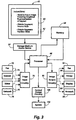
- Fig. 3 shows general components of a software product and of a machine in which it can be used.
- Fig. 1 shows input image 10 showing graphical representation 12 of a layout.
- Graphical representation 12 can, for example, be a human-produced sketch.
- Graphical representation 12 illustratively includes segment representations 14 and 16.
- Each segment representation illustratively includes a character indicating an image source, and each segment representation is positioned within graphical representation 12 to indicate a position for an image from the indicated image source.
- a machine receiving data defining input image 10 can respond by automatically obtaining segment source data 20 indicating a source for each segment.
- the machine can also respond by automatically obtaining segment position data 22 indicating a position for each segment.
- the general acts in Fig. 2 begin in box 40 by receiving input image data defining an input image that shows a graphical representation of a layout.
- the act in box 42 uses the input image data to obtain segment source data indicating a source for each segment and segment position data indicating a position for each segment.
- Fig. 3 shows software product 60, an article of manufacture that can be used in a system that includes components like those shown in Fig. 3.
- Software product 60 includes data storage medium 62 that can be accessed by storage medium access device 64.
- Data storage medium 62 could, for example, be a magnetic medium such as a set of one or more tapes, diskettes, or floppy disks; an optical medium such as a set of one or more CD-ROMs; or any other appropriate medium for storing data.
- Data storage medium 62 stores data that storage medium access device 64 can provide to processor 66.
- Processor 66 is connected for accessing memory 68, which can include program memory storing data indicating instructions that processor 66 can execute and also data memory storing data that processor 66 can access in executing the instructions.
- Processor 66 is also connected for receiving data defining images from image input circuitry 70.
- the data could be obtained from facsimile (fax) machine 72; from scanner 74; from editor 76, which could be a forms editor or other interactive image editor controlled by user input devices such as a keyboard and mouse or a pen- or stylus-based input device; or from network 78, which could be a local area network or other network capable of transmitting data defining an image.
- software product 60 includes data stored by storage medium 62.
- the stored data include data indicating image processing instructions 80, which processor 66 can execute to perform acts like those in Fig. 2.
- processor 66 receives input image data defining an input image set from image input circuitry 70.
- the input image set shows a graphical representation of a layout Processor 66 uses the input image data to obtain segment source data indicating a source for each segment and segment position data indicating a position for each segment
- Processor 66 can also be connected for providing data defining images to image output circuitry 90.
- software product 60 could include data indicating instructions processor 66 can execute to use the segment source data and the segment position data to obtain output image data defining an output image.
- the output image could have a layout as represented by the graphical representation.
- the output image data could be provided to image output circuitry 90, and could in turn be provided to fax machine 92, to printer 94, to display 96, or to network 98.
- the segment source data and the segment position data could also be used to provide control signals.
- memory 68 could store control instructions processor 66 can execute to use the segment source data and the segment position data to obtain control data defining control signals.
- the control data could be provided to control output circuitry 100, which could respond by providing control signals to system 102.
- segment source data and the segment position data could instead be stored in memory 68 for possible future use. This would be appropriate, for example, where information indicating an operation to be performed on an input image set has not been obtained at the time data defining the input image set is received.
- FIG. 4 illustrates ways in which a user can provide an image showing a graphical representation of a layout made by hand.
- Fig. 5 illustrates ways in which a user can provide an image showing a graphical representation of a layout by interacting with a machine.
- Fig. 4 shows at the top an example of an image set showing a graphical representation of a layout and two image source sheets.
- Image 100 shows a graphical representation of a layout.
- the graphical representation includes two segment representations, one above the other and each occupying approximately half the area of the graphical representation.
- the upper segment representation includes one connected component, and the lower segment representation includes two.
- Images 102 and 104 show image source sheets, in each of which a sketch or other marks indicating an image is enclosed by a rectangular connected component with a line separating a region at the upper left corner.
- the upper left region includes one connected component, as in the upper segment representation; in image 104, the upper left region includes two, as in the lower segment representation.
- the number of connected components can be counted to obtain data indicating that image 102 includes the source for the segment represented by the upper segment representation in image 100 and image 104 includes the source for the segment represented by the lower segment representation in image 100.
- Any of the images in Fig. 4 could be a human-produced sketch made by marking actions performed on a marking medium by hand. Or the images could be obtained in any other appropriate way.
- scanner 130 can receive the sheet. Scanner 130 operates on the sheet to provide data defining an image showing a graphical representation of a layout or showing an image source sheet.
- marking medium is a marking surface of an electronic device that can sense marks
- encoder 132 can receive signals from the electronic device and use the signals to obtain data defining an image showing a graphical representation of a layout or showing an image source sheet. This data can then be provided to printer 134 to obtain a sheet on which marks are printed, and this sheet can be provided to scanner 130.
- Scanner 130 provides data defining an image showing a graphical representation of a layout or showing an image source sheet.
- Fig. 4 also shows that data from encoder 132 could be used directly as data defining an image showing a graphical representation of a layout or showing an image source sheet. This would be appropriate if encoder 132 could provide data defining an image in response to marking actions.
- Fig. 5 shows machine 150, which could be a personal computer, a workstation, or another data processing system.
- Machine 150 includes processor 152; display 154; keyboard 156; pointing device 158, illustratively a mouse; and screen position indicating device 160, illustratively a stylus.
- a user can operate keyboard 156 and pointing device 158 to provide signals to processor 152.
- a user can perform marking actions with screen position indicating device 160 on the surface of display 154 to provide signals to processor 152.
- processor 152 presents and modifies image 162 on display 154, so that the user can continue to provide signals until image 162 shows a desired graphical representation of a layout. Then the user can provide a signal requesting that processor 152 provide data defining image 162.
- Processor 152 could execute a number of types of software to permit a user to produce an image in the manner described above.
- Processor 152 could execute document editing software or image editing software, for example.
- an image set showing a graphical representation of a layout could be produced in any of the ways shown in Figs. 4 and 5 or in any other appropriate way.
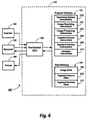
- Fig. 6 shows a system in which the general features described above have been implemented.
- System 180 in Fig. 6 includes workstation 182, a Sun SPARCStation 10 workstation.
- Scanner 184 can be a conventional scanner such as a Xerox Datacopy GS Plus scanner.
- Printer 186 can be a conventional printer such as a Xerox laser printer.
- Network 188 can be a conventional network operating in accordance with a standard protocol, such as the Ethernet protocol.
- Workstation CPU 190 is connected to receive data from scanner 184 and network 188 and is connected to provide data to printer 186 and network 188.
- CPU 190 can receive data defining an image showing a graphical representation of a layout from scanner 154 as described above in relation to Fig. 4.
- CPU 190 can receive data defining an image obtained in the manner described above in relation to Fig. 5 from network 188.
- workstation CPU 190 is connected to access program memory 192 and data memory 194 and other conventional workstation peripherals (not shown).
- Data memory 194 is illustratively storing image data 196 defining an image set showing a graphical representation of a layout
- Program memory 192 stores instructions CPU 190 can execute to perform operations implementing the general acts in Fig. 2.
- CPU 190 executes operating system instructions 200 that provide a Unix operating system (Unix is a registered trademark) or other appropriate operating system.
- Unix operating system Unix is a registered trademark
- Each of the other sets of instructions stored by program memory 192 can be obtained from source code in a conventional programming language such as Lisp, C, or the like with conventional compiler or interpreter techniques. When executed, these other instructions make calls to operating system instructions 200 in a conventional manner.
- the instructions can be obtained from source code in a conventional programming language such as Lisp, C, or the like with conventional compiler or interpreter techniques that produce object code.
- a machine can store data indicating the source code or the resulting object code on a data storage medium in manufacturing a software product as described above in relation to Fig. 3, with the source code or object code being stored for access by a storage medium access device when the software product is used in a machine like system 180.
- CPU 190 In executing image receiving instructions 202, CPU 190 receives data defining an image set and stores it in data memory 194, as illustrated by image data 196.
- the data defining the image set may be received from scanner 184 or network 188.
- CPU 190 calls segment source instructions 206 and segment position instructions 208.
- Image processing instructions 204 also perform other operations relating to analysis of graphical representations of layouts.
- CPU 190 calls analysis instructions 210 to perform basic geometric analysis of the image set defined by image data 196, producing segment source data 220.
- Segment source data 220 indicate a source for each segment represented in the graphical representation shown by the image set.
- CPU 190 calls analysis instructions 210 to perform basic geometric analysis of the image set defined by image data 196, producing segment position data 222.
- Segment position data 222 indicate a position for each segment
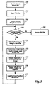
- Fig. 7 shows acts in executing image processing instructions 204 in Fig. 6.
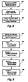
- Fig. 8 shows acts in executing segment source instructions 206 in Fig. 6.
- Fig. 9 shows acts in executing segment position proportions instructions 208 in Fig. 6.
- Figs. 7-9 are performed on items of data, each of which defines an image. Each item is referred to as a "data image.” Some data images can be used in obtaining others. In general, all of the data images define images with the same number of pixels, and each operation produces an image with the same number of pixels. An operation on two images typically uses values of pairs of pixels to produce, for each pair, a pixel value in an image being produced; within each pair, one pixel is from each image and the two pixels in the pair are both at the same location as the pixel value in the image being produced. Many examples of such operations are described in concurrently filed European Patent Applications corresponding to US Serial Nos. 08/157,600 and 08/157,804.
- the act in box 240 in Fig. 7 begins by receiving data defining an input image set.
- the input image data may have been received previously by executing image receiving instructions 202, and may be provided with a call to image processing instructions 204.
- the call can indicate layout image data defining an image showing a graphical representation of a layout and source image data defining one or more source images that show marks indicating information about image sources for segments of the layout.
- the act in box 242 prepares by opening a page description language (PDL) file, such as a PostScript file.
- PDL page description language
- the act in box 244 uses the layout image data to obtain data indicating the width and height of the layout. This can be done by first obtaining the difference between the x coordinates of the leftmost and rightmost ON pixels in the graphical representation and the difference between the y coordinates of the topmost and bottommost ON pixels in the graphical representation.
- the width can be set to a constant value of 8.5 and the height can be set to the product of 8.5 times the ratio of the height to the width.
- the height can be loaded into the PDL file, if appropriate.
- the act in box 250 then begins an iterative loop that handles each of the source images defined by the source image data.
- the act in box 252 begins each iteration by using data defining the next source image to obtain data indicating the source identifier, which can be a count of connected components.
- the source identifier is obtained at this point to provide a file name within the PDL file.
- the act in box 252 can be implemented by obtaining a holes data image then using the holes data image to obtain a filled data image.
- the act in box 252 can use the filled data image to obtain a top left component data image in which each pixel in the top left component in the filled data image is ON.
- the act in box 252 can AND the top left component data image with the source image to obtain a source identifier data image showing the connected components in the top left subregion of the source image.
- the act in box 252 can then count the connected components in the source identifier data image to obtain the source identifier.
- the act in box 252 could obtain the top left component data image by first obtaining a distances data image in which each pixel is labeled with its distance from the top left corner of the image. The act in box 252 can then perform a spread operation to obtain a top left distances data image in which each pixel in each connected component in the filled data image is labeled with the minimum distance from the distances data image of the pixels in the connected component. The act in box 252 can perform an operation to find the minimum distance of the pixels in the top left distances data image, and this minimum distance can be compared with the label of each pixel in the top left distances data image to obtain the top left component data image.
- the act in box 252 could alternatively obtain the top left component data image using a seed data image in which only the top left pixel is ON.
- the act in box 252 could obtain a neighbor identifier data image in which each pixel is labeled with a unique identifier of a near connected component in the filled data image, using a read operation.
- the act in box 252 could then perform a spread operation to obtain a labeled data image in which each pixel has the maximum value from the seed data image of pixels that have the same value in the neighbor identifier data image.
- the act in box 252 can then AND the labeled data image with the filled data image to obtain the top left component data image.
- the act in box 254 then categorizes the contents of the source image and obtains data indicating a rendered version of the source image.
- the act in box 254 then loads the rendered version into the PDL file opened in box 242 using the file name from box 252.
- the act in box 254 can be implemented by obtaining a bottom right component data image similar to the top left component data image described in relation to box 252 above. Then the act in box 254 can use the bottom right component data image to obtain a rendered image in the manner described in concurrently filed herewith European Patent Application corresponding to US Serial No. 08/158,063.
- Several categories of graphical representations can be categorized and rendered. Significant categories include node-link structures, parallel length graphs, proportioned parts graphs, row/column representations, perimeter relationship representations and two-dimensional graphs. If a source image is not an instance of a category that can be rendered, the source image can be rendered as a rectangular bitmap shaped in the same proportions as a bounding box around the ON pixels in the bottom right component data image.
- the act in box 256 uses the source identifier from box 252 to obtain a segment source data image showing the segment of the graphical representation whose source is the source image.
- the act in box 256 can be implemented as described below in relation to Fig. 8.
- the act in box 258 uses the segment source data image from box 256 to obtain segment position data indicating the left x coordinate, the right y coordinate, the width, and the height of the segment in the layout.
- the act in box 258 can be implemented as described below in relation to Fig. 9.
- box 260 loads the segment position data from box 258 into the PDL file opened in box 242 using the file name from box 252.
- the PDL file is closed and returned in box 262.
- the PDL file can then be provided to a printer for printing, for example.
- the act in box 280 uses the layout image data from box 240 in Fig. 7 to obtain a data image in which each pixel in each segment of the layout is labeled with a segment identifier.
- the act in box 280 can be implemented by using the layout image data to obtain an internals data image and can use the internals data image to obtain a shrink data image in which only one pixel in each connected component in the internals data image is ON.
- the act in box 280 can also use the layout image data to obtain a holes data image, which can in turn be used to obtain a holes data image as described above in relation to box 252 in Fig. 7.
- the act in box 280 can then use the shrink data image and the filled data image to perform a spread operation, obtaining a segment identifier data image in which each pixel in each connected component in the filled data image is labeled with the sum of the number of ON pixels in the shrink data image that are in the connected component
- the act in box 282 obtains data indicating the source image's identifier.
- the act in box 282 can be implemented as described above in relation to box 252 in Fig. 7.
- the act in box 284 can then, at each pixel, compare the source image's identifier from box 282 with the value in the segment identifier data image from box 280, obtaining a segment data image in which each pixel is ON if its value in the segment identifier data image is equal to the source image's identifier.
- the segment data image therefore shows one of the segments of the layout.
- the segment data image is segment source data because it indicates that the source of the image for the segment shown is the source image being handled by the iterative loop of Fig. 7.
- the act in box 300 uses the layout image data from box 240 in Fig. 7 and the segment data image from box 284 in Fig. 8 to obtain four values for each image--left x coordinate, bottom y coordinate, width, and height.
- the act in box 300 can be implemented as described above in relation to box 244 in Fig. 7.
- the acts in boxes 302, 304, 306, and 308 then obtain four similar values that together indicate the position of the segment in the layout.
- the left and bottom coordinates indicate a reference point and the width and height indicate the extent of the segment from the reference point rightward and upward.
- the act in box 302 obtains the left x coordinate by obtaining the difference between the left x coordinates of the layout and the segment from box 300, then dividing the difference by the layout width from box 300.
- the act in box 304 obtains the bottom y coordinate by obtaining the difference between the bottom y coordinates of the layout and the segment from box 300, then dividing the difference by the layout height from box 300.
- the act in box 306 obtains the width by dividing the segment width from box 300 by the layout width from box 300.
- the act in box 308 obtains the height by dividing the segment height from box 300 by the layout height from box 300.
- a PDL file After a PDL file is obtained as described above, it can be provided to a printer or other image output device.
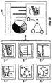
- Fig. 10 shows an example obtained with the implementation described above.
- Input image 320 shows a graphical representation of a layout with five image segments.
- Input images 322, 324, 326, 328, and 330 show five source images for the five image segments. Images 322 and 330 show source images that cannot be rendered by the current implementation.
- Image 324 shows a sketch of a node-link structure that can be rendered.
- Image 326 shows a sketch of a parallel length graph that can be rendered as described in concurrently filed European Patent Application corresponding to US Serial No. 08/158,062.
- Image 328 shows a sketch of a proportioned parts graph that can be rendered as described in concurrently filed European Patent Application corresponding to US Serial No. 08/157,856.
- Output image 340 shows a resulting layout with five image segments as represented by the graphical representation in image 320.
- Source images 324, 326, and 328 have been categorized and rendered as precisely formed images showing, respectively, a directed graph, a vertical bar graph, and a pie chart. All of the source images have been positioned and scaled according to their positions in the layout.
- segment source data uses particular operations described above to obtain segment source data, segment position data, and other data from an image set showing a graphical representation of a layout and showing source images. Numerous other combinations of operations besides those described above could be used to obtain such data.
- an input image set is provided so that a layout image is separate from source images.
- a layout image could be provided that can be automatically categorized similar to the manner in which other graphical representations are categorized making it possible to provide the layout image and the source images together in any order.
- each segment of the layout has a source image in the input image set.
- One or more of the source images could instead be retrieved from memory or elsewhere using an address or other information from an input image set.
- the implementation described above uses a graphical representation of a layout that includes a rectangle subdivided by lines. Other graphical representations of layouts could be used.
- identifiers are numbers of connected components within segment representations.
- the identifiers could be alphanumeric characters, if satisfactory character recognition techniques were available. Or the identifiers could be other distinguishable marks. Further, identifiers need not be positioned within the segment representations, but could be positioned outside the layout, with lines connecting them to their respective segment representations.
- each sheet bearing a sketch of a layout and each other sheet showing an image source.
- the number of sheets might be reduced by drawing lines connecting each segment in the layout to an image representation on the same page but outside the layout.
- Each image representation could, for example, include a segment identifier or could include a sketch of a graphical representation to be categorized and rendered to provide a source image.
- the implementation described above analyzes each source image to obtain a source identifier from the top left and the information indicating a source image from the lower right.
- the source identifier and information indicating a source image could be included in a source image in other ways.
- implementations described above can operate on human-produced images showing graphical representations that satisfy certain constraints.
- a machine could be implemented to produce images satisfying the same constraints automatically, in which case the implementations could be applied to machine-produced imaged.
- image analysis results could be used for a variety of other purposes.
- the results of image analysis could be stored to preserve a graphical representation generated during a meeting using a tool such as a computer-controlled whiteboard device.
- One of the advantages of the implementation described above is that the user can draw a relatively simple sketch to indicate a relatively complicated graphical representation that can be rendered automatically in response to the sketch. Therefore, the sketch cannot specify all the relevant parameters of the output image, making it necessary for parameters that are not specified to default sensibly.
- default parameters are supplied by rendering procedures. A user could instead provide defaults, such as in an initialization file. Defaults could be provided for specific categories and for specific rendering systems.
- a layout could be reorganized by providing a graphical representation of a new layout, mapping the regions of the previous layout to the new layout.
- a layout could be incrementally modified using a markup technique to indicate a segment of the layout and an operation such as a geometric transformation to be performed on the indicated segment. For this purpose, editing techniques could be used as described in concurrently filed European Patent Application corresponding to US Serial No. 08/157,804.
- Fig. 6 employs a workstation CPU that executes image processing instructions.
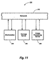
- Fig. 11 shows an alternative implementation that uses an image processing server. This implementation can provide the usual advantages of server architectures, including economy, speed, and sharing of resources.
- System 390 in Fig. 11 includes network 392, workstation 394, storage server 396, and image processing server 398.
- a user can operate workstation 394 to provide requests on network 392 for storage of data defining images, such as from a scanner or other source.
- storage server 396 can store the data.
- the user can operate workstation 394 to provide requests for image processing operations like those described above.
- image processing server 388 can perform the requested operations, executing instructions like those described above in relation to Fig. 6.
- the invention could be applied in many ways.
- the techniques described above can be used to rapidly assemble a nicely-rendered graphic document based on hand-drawn sketches of the document's layout and the segments of the layout. In this way, one could generate slides for a talk or experiment with the layout of a poster or an illustration page of a paper. Or one could assemble items drawn from various reference materials in a library with one's own diagrammatic and textual notes to obtain a summary of one's research.
- Fig. 12 shows how the techniques described above could be applied in a personal computer that can operate as a fax server.
- Fig. 13 illustrates how the techniques described above could be applied in a copier.
- System 400 in Fig. 12 includes CPU 402, which can be the CPU of a personal computer such as an IBM PC compatible machine.
- CPU 402 is connected to receive user input signals from keyboard 404 and mouse 406, and can present images to a user through display 408.
- CPU 402 is also connected to a number of other peripheral devices, illustratively including disk drive 410. modem 412, scanner 414, and printer 416.
- Program memory 420 stores operating system (OS) instructions 422, which can be a version of DOS; user interface instructions 424; fax server instructions 426; and image processing instructions 428.
- Fax server instructions 426 can be similar to the PaperWorksTM software product of Xerox Corporation.
- Image processing instructions 428 can be implemented as described above in relation to image processing instructions 204 in Fig. 6 and in relation to Figs. 7-9. Fax server instructions 426 and image processing instructions 428 could be obtained in the form of a software product stored on a floppy disk, diskette, or CD-ROM, and accessed for storage in program memory 420 by disk drive 410.
- Data memory 440 stores input image data 442, segment source data 444, segment position data 446, and output image data 448 as described above in relation to Figs. 6-9.
- System 400 can obtain input image data 442 defining an image set that shows a graphical representation of a layout in many ways: Data defining an image showing a graphical representation of a layout could be produced interactively as described above in relation to Fig. 5, such as by executing user interface instructions 424. Any appropriate user interface techniques could be used, including pen-based techniques. Data defining a previously produced image showing a graphical representation of a layout could be retrieved from a storage medium by disk drive 410. Data defining an image showing a graphical representation of a layout could be obtained from scanner 414 as described above in relation to Fig. 4. A user could produce data defining an image showing a graphical representation of a layout elsewhere and provide it to system 400 through modem 412, such as by making a facsimile transmission to modem 412.
- CPU 402 could execute fax server instructions 426 in response to a request received by facsimile transmission through modem 412.
- the request could include a form indicating a layout operation and also indicating an output image destination such as a fax machine or printer 416.
- the request could also include data defining an image showing a graphical representation of a layout or could indicate an image previously obtained by system 400.
- Fax server instructions 426 could include calls to image processing instructions 428 to perform acts like those shown in Figs. 7-9 if the request indicates a layout operation. Execution of fax server instructions 426 could further provide data defining an output image showing a layout as represented by the graphical representation, which could be provided to modem 412 for facsimile transmission or to printer 416 for printing.
- copier 460 can be a digital copier or other electronic reprographics system.
- Scanning circuitry 462 obtains data defining input image 464 showing a graphical representation of a layout.
- User interface circuitry 470 includes touch sensing device 472, which can be a push button, a heat or pressure sensitive element, a capacitance sensing element, or other device for sensing a touching action. When a user touches device 472, user interface circuitry 470 provides touch data indicating that device 472 has been touched.
- Processing circuitry 480 uses the touch data to obtain request data indicating a request for a layout operation. Then, responding to the request, processing circuitry 480 uses data defining input image 464 to automatically obtain segment source data indicating each segment's source and segment position data indicating each segment's position. Processing circuitry 480 then uses the segment source data and the segment position data to obtain data defining an output image that shows a layout with segments from the indicated sources at the indicated positions. This data is provided to printing circuitry 490 for printing of output image 492.
Landscapes
- Engineering & Computer Science (AREA)
- Physics & Mathematics (AREA)
- Computer Vision & Pattern Recognition (AREA)
- General Physics & Mathematics (AREA)
- Theoretical Computer Science (AREA)
- Geometry (AREA)
- Artificial Intelligence (AREA)
- Multimedia (AREA)
- Processing Or Creating Images (AREA)
- Editing Of Facsimile Originals (AREA)
- Image Analysis (AREA)
Claims (18)
- Verfahren, welches umfasst:gekennzeichnet dadurch, dassdas Erlangen von Eingabebilddaten, welche einen Eingabebildsatz (100, 200, 104; 320, 322, 324, 326, 328, 330; 442) definieren, der eine grafische Darstellung (12; 100; 320) eines Layouts zeigt, wobei die grafische Darstellung (12; 100; 320) Segmentquelleninformationen einschließt, welche Quellenbilder (102, 104; 322, 324, 326, 328, 330) für Segmente im Layout angeben, und Segmentpositionsinformationen, die die Positionen der Segmente innerhalb des Layouts angeben, wobei die Segmentquelleninformationen für jedes Segment Segmentbezeichnermarkierungen einschließen, die einen Segmentbezeichner angeben, welcher jedes Segment bezeichnet, unddie Verwendung der Bildeingabedaten, um daraus Segmentpositionsdaten (22; 222; 446) zu erhalten, welche eine Position für jedes der Segmente angeben,das Ermitteln von Segmentbezeichnerdaten, welche den Segmentbezeichner angeben, der durch die Segmentbezeichnermarkierungen angezeigt wird, unddie Verwendung der Segmentbezeichnerdaten zur Ermittlung der Segmentquellendaten (20, 220, 440), wobei die Segmentquellendaten ein Quellenbild für jedes Segment angeben,das Layout zwei oder mehr Segmente (14, 16) einschließt,der Eingabebildsatz weiterhin Bildquellenblätter zeigt, die Quellenbilder definieren,wobei jedes Bildquellenblatt Quellenbezeichnermarkierungen enthält, wobei die Quellenbezeichnermarkierungen einen Quellenbezeichner angeben, der das Quellenbild bezeichnet,wobei das Verfahren weiterhin die folgenden Schritte umfasst:die Verwendung der Eingabebilddaten zur Ermittung der Bildquellendaten, welche für jedes Segment das entsprechende Bildquellenblatt angeben,die Ermittlung der Quellenbezeichnerdaten, welche den Quellenbezeichner angeben, der durch die Quellenbezeichnermarkierungen angegeben wird, unddas Abgleichen der Quellenbezeichnerdaten und der Segmentbezeichnerdaten zum Ermitteln des Quellenbildes, welches jedem Segment entspricht.
- Verfahren nach Anspruch 1, wobei der Eingabebildsatz ein vom Menschen erstelltes Bild einschließt (320, 322, 324, 326, 328, 330), wobei das vom Menschen erstellte Bild die grafische Darstellung zeigt.
- Verfahren nach Anspruch 2, wobei das vom Menschen erstellte Bild eine Skizze des Layouts zeigt, wobei die Skizze die grafische Darstellung bildet.
- Verfahren nach einem der Ansprüche 1 bis 3, welches weiterhin umfasst:
die Verwendung der Segmentquellendaten (20; 220; 444) und der Segmentpositionsdaten (22; 222; 446) zum Ermitteln der Ausgabebilddaten, welche ein Bild definieren, das ein Layout gemäß der grafischen Darstellung (12) ein-schließt. - Verfahren nach Anspruch 4, wobei die Segmentpositionsdaten (22; 222; 446) für jedes der Segmente eine Breite und eine Höhe angeben, wobei der Schritt des Verwendens der Segmentquellendaten (20; 220; 444) und der Segmentpositionsdaten umfasst:
die Verwendung der Segmentpositionsdaten (22; 222; 446) zum Skalieren jedes der Segmente, damit diese zu der von den Segmentpositionsdaten (22; 222; 446) angegebenen Breite und Höhe passen. - Verfahren nach Anspruch 4 oder 5, wobei die Segmentpositionsdaten für jedes der Segmente einen Bezugspunkt angeben, wobei der Schritt der Verwendung der Segmentquellendaten (120; 222; 444) und der Segmentpositionsdaten (22; 222; 446) umfasst:
die Verwendung der Segmentpositionsdaten (22; 222; 446) zum Positionieren jedes Segments am Bezugspunkt, der von den Segmentpositionsdaten (22; 222; 446) angegeben wird. - Verfahren nach einem der Ansprüche 4 bis 6, wobei der Eingabebildsatz weiterhin eine Skizze (320, 322, 324, 326, 328, 330) einer grafischen Quellendarstellung zeigt, wobei die Segmentquellendaten angeben, dass die Skizze ein Quellenbild des ersten Segments ist, und der Schritt der Verwendung der Segmentquellendaten und der Segmentpositionsdaten zur Ermittlung der Ausgabebilddaten des Weiteren umfasst:die Verwendung der Eingabebilddaten zur Ermittlung der Inhaltsdaten, welche Informationen angeben, die von der grafischen Quellendarstellung repräsentiert werden,die Verwendung der Inhaltsdaten zur Ermittlung von Daten, die eine präzise ausgebildete grafische Darstellung der von den Inhaltsdaten angegebenen Informationen definieren, unddie Verwendung der Daten, welche die präzise ausgebildete grafische Darstellung definieren, um dadurch die Ausgabebilddaten zu erhalten.
- Verfahren nach Anspruch 7, wobei die grafische Quellendarstellung eine Knoten-Verknüpfungsstruktur, ein Graph mit paralleler Länge, ein Proportionalgraph, eine Reihen-/Spalten-Darstellung, eine Darstellung des Umfangsverhältnisses oder ein zweidimensionaler Graph ist.
- Verfahren nach einem der Ansprüche 1 bis 8, wobei die grafische Darstellung des Layouts zwei oder mehr Segmentdarstellungen (14, 16) enthält, und der Schritt der Verwendung der Eingabebilddaten zur Ermittlung der Segmentquellendaten (20; 220; 444) und der Segmentpositionsdaten umfasst:die Verwendung der Eingabebilddaten zur Ermittlung der relativen Positionsdaten, welche die Position jeder Segmentdarstellung in Bezug auf die grafische Darstellung angeben, unddie Verwendung der relativen Positionsdaten zur Ermittlung der Segmentpositionsdaten.
- Verfahren nach Anspruch 9, wobei die grafische Darstellung des Layouts eine rechtwinklige Begrenzung und parallel zu den Seiten der Begrenzung verlaufende Linien einschließt, welche die Segmentdarstellungen innerhalb der Begrenzung bilden, wobei jede Segmentdarstellung rechtwinklig ist, wobei der Schritt der Verwendung der Eingabebilddaten zur Ermittlung der relativen Positionsdaten umfasst:die Verwendung der Eingabebilddaten zur Ermittlung der Begrenzungspositionsdaten, welche die Position der Begrenzung angeben, und der Positionsdaten des ersten Segments, welche die Position des ersten Segments der Darstellung angeben, unddie Verwendung der Begrenzungspositionsdaten und der Positionsdaten des ersten Segments zur Ermittlung der relativen Positionsdaten des ersten Segments, welche eine Position der ersten Segmentdarstellung in Bezug auf die Begrenzung angibt, wobei die relativen Positionsdaten die relativen Positionsdaten des ersten Segments einschließen.
- Verfahren nach Anspruch 1, wobei die Quellenbezeichnermarkierungen eine Anzahl verbundener Komponenten bilden, die den Quellenbezeichner angeben, wobei die Segmentbezeichnermarkierungen die gleiche Anzahl verbundener Komponenten bilden,wobei der Schritt des Ermittelns der Quellenbezeichnerdaten umfasst:
das Ermitteln einer ersten Zählangabe, welche die Anzahl verbundener Komponenten angibt, die von den Quellenbezeichnermarkierungen gebildet werden,wobei der Schritt des Ermittelns der Segmentbezeichnerdaten umfasst:
das Ermitteln der zweiten Zählangabe, welche die Anzahl verbundener Komponenten angibt, die von den Segmentbezeichnermarkierungen gebildet wird. - Maschine mit:dadurch gekennzeichnet, dasseiner Bildeingabeschaltung (70) zum Ermitteln von Daten, die Bilder als Eingabesignale definieren,Speicher (68; 192, 194; 420, 440) zum Speichern von Daten undeinem Prozessor (66; 402), der zum Empfangen der Bilder definierenden Daten aus der Bildeingabeschaltung (70) angeschlossen ist sowie zum Zugriff auf die im Speicher gespeicherten Daten,wobei die im Speicher gespeicherten Daten Anweisungsdaten (192; 420) umfassen, welche Bildverarbeitungsanweisungen angeben, die der Prozessor ausführen kann, wobei der Prozessor bei der Ausführung der Bildverarbeitungsanweisungen:Eingabebilddaten aus der Bildeingabeschaltung empfängt, wobei die Eingabebilddaten einen Eingabebildsatz (100, 102, 104; 320, 322, 324, 326, 328, 330; 442) definieren, welcher eine grafische Darstellung (12; 100; 320) eines Layouts zeigt, wobei die grafische Darstellung Segmentquelleninformationen einschließt, die Quellenbilder (102, 104; 322, 324, 326, 328, 330) für Segmente im Layout angeben, und Segmentpositionsinformationen, die Positionen der Segmente innerhalb des Layouts angeben, wobei die Segmentquelleninformationen für jedes Segment Segmentbezeichnermarkierungen einschließen die einen Segmentbezeichner angeben, welcher jedes Segment bezeichnet, unddie Eingabebilddaten dazu verwendet, Segmentpositionsdaten (22; 222; 446) zu ermitteln, welche eine Position für jedes der Segmente angeben,Segmentbezeichnerdaten ermittelt, die den Segmentbezeichner angeben, der durch die Segmentbezeichnermarkierungen angegeben wird, unddie Segmentbezeichnerdaten dazu verwendet, die Segmentquellendaten (20, 220, 440) zu ermitteln, wobei die Segmentquellendaten ein Quellenbild angeben,das Layout zwei oder mehr Segmente (14, 16) einschließt,der Eingabebildsatz weiterhin Bildquellenblätter zeigt, die diese Quellenbilder definieren, wobei jedes Bildquellenblatt Quellenbezeichnermarkierungen einschließt, wobei die Quellenbezeichnermarkierungen einen Quellenbezeichner angeben, der das Quellenbild bezeichnet,der Prozessor bei der Ausführung der Bildverarbeitungsanweisungen die folgenden Schritte durchführt:Verwendung der Eingabebilddaten zur Ermittlung der Bildquellendaten, welche für jedes Segment das entsprechende Bildquellenblatt angeben,Ermittlung der Quellenbezeichnerdaten, die den Quellenbezeichner angeben, der von den Quellenbezeichnermarkierungen angegeben wird, undAbgleich- der Quellenbezeichnerdaten mit den Segmentbezeichnerdaten, um dadurch das Quellenbild zu ermitteln, das jedem Segment entspricht.
- Maschine nach Anspruch 12, wobei die Eingabebildschaltung zum Empfangen von Faxübertragungen (72) angeschlossen ist.
- Verfahren nach Anspruch 12 oder 13, wobei die Maschine weiterhin eine Bildausgabeschaltung (90) zur Bereitstellung von Daten umfasst, welche Bilder als Ausgangssignale definieren, wobei der Prozessor bei der Ausführung der Bildverarbeitungsanweisungen weiterhin:die Segmentquellendaten und die Segmentpositionsdaten dazu verwendet, um Ausgabebilddaten (448) zu ermitteln, welche ein Bild definieren, das ein Layout gemäß der grafischen Darstellung einschließt, unddie Ausgabebilddaten an die Bildausgabeschaltung (90) sendet.
- Die Maschine nach Anspruch 14, wobei die Ausgabebildschaltung zur Bereitstellung von Faxübertragungen (72) angeschlossen ist.
- Maschine nach einem der Ansprüche 12 bis 15, wobei die Maschine ein Bildverarbeitungsserver (398) ist, wobei der Bildverarbeitungsserver an ein Netzwerk zum Empfang von Anforderungen zu Bildverarbeitungsoperationen angeschlossen ist, wobei das Netzwerk die Bildeingabeschaltung einschließt, wobei die Anweisungsdaten weiterhin Anforderungssteueranweisungen enthalten, die der Prozessor ausführen kann, wobei der Prozessor während der Ausführung der Anforderungssteueranweisungen bestimmt, ob die Bildverarbeitungsanweisungen ausgeführt werden.
- Maschine nach einem der Ansprüche 12 bis 16, wobei die Maschine ein Faxserver (400) oder ein Kopierer (460) ist.
- Erzeugnis zur Verwendung in einer Maschine, welches aufweist: -wobei das Erzeugnis umfasst:eine Bildeingabeschaltung (70) zum Ermitteln von Bilder definierenden Daten als Eingabesignale,eine Speichermedium-Zugriffsvorrichtung (64) für den Zugriff auf ein Medium, welches Daten speichert, undeinen Prozessor (66; 402), der zum Empfang von Bilder definierenden Daten aus der Bildeingabeschaltung angeschlossen ist, wobei der Prozessor weiterhin für den Empfang von Daten aus der Speichermedium-Zugriffsvorrichtung angeschlossen ist,dadurch gekennzeichnet, dassein Speichermedium, auf das mit der Speichermedium-Zugriffsvorrichtung zugegriffen werden kann, wenn das Erzeugnis in dem System verwendet wird, undDaten, die von dem Speichermedium gespeichert werden, sodass die Speichermedium-Zugriffsvorrichtung die gespeicherten Daten dem Prozessor zur Verfügung stellen kann, wenn das Erzeugnis im System zur Anwendung kommt, wobei die gespeicherten Daten Anweisungsdaten (192; 420) umfassen, die Anweisungen angeben, welche der Prozessor ausführen kann, wobei der Prozessor bei der Ausführung der Anweisungen:Eingabebilddaten aus der Bildeingabeschaltung empfängt, wobei die Eingabebilddaten einen Eingabebildsatz (100, 102, 104; 320, 322, 324, 326, 328, 330; 442) definieren, der eine grafische Darstellung (12; 100; 320) eines Layouts zeigt, wobei die grafische Darstellung (12; 100; 320) Segmentquelleninformationen einschließt, welche Quellenbilder (102, 104; 322, 324, 326, 328, 330) für Segmente im Layout angeben, und Segmentpositionsinformationen, welche Positionen der Segmente innerhalb des Layouts angeben, wobei die Segmentquelleninformationen für jedes Segment Segmentbezeichnermarkierüngen einschließen, die einen jedes Segment bezeichnenden Segmentbezeichner aufweisen, unddie Eingabebilddaten dazu verwendet, Segmentpositionsdaten (22; 222, 446) zu ermitteln, welche eine Position für jedes der Segmente angeben,Segmentbezeichnerdaten ermittelt, die den Segmentbezeichner angeben, der von den Segmentbezeichnermarkierungen angegeben wird, unddie Segmentbezeichnerdaten dazu verwendet, die Segmentquellendaten (20; 220; 440) zu bestimmen, wobei die Segmentquellendaten ein Quellenbild für jedes Segment angeben,das Layout zwei oder mehr Segmente (14, 16) einschließt,der Eingabebildsatz weiterhin Bildquellenblätter zeigt, die diese Quellenbilder definieren, wobei jedes Bildquellenblatt Quellenbezeichnermarkierungen einschließt, wobei die Quellenbezeichnermarkierungen einen Quellenbezeichner angeben, der das Quellenbild bezeichnet,der Prozessor bei der Ausführung der Bildverarbeitungsanweisungen die folgenden Schritte durchführt:Verwendung der Eingabebilddaten zur Ermittlung der Bildquellendaten, welche für jedes Segment das entsprechende Bildquellenblatt angeben,Ermittlung der Quellenbezeichnerdaten, die den Quellenbezeichner angeben, der von den Quellenbezeichnermarkierungen angegeben wird, undAbgleich der Quellenbezeichnerdaten mit den Segmentbezeichnerdaten, um dadurch das Quellenbild zu ermitteln, das jedem Segment entspricht.
Applications Claiming Priority (2)
| Application Number | Priority Date | Filing Date | Title |
|---|---|---|---|
| US08/158,132 US5455898A (en) | 1993-11-24 | 1993-11-24 | Analyzing an image showing a graphical representation of a layout |
| US158132 | 1993-11-24 |
Publications (3)
| Publication Number | Publication Date |
|---|---|
| EP0654754A2 EP0654754A2 (de) | 1995-05-24 |
| EP0654754A3 EP0654754A3 (de) | 1995-11-22 |
| EP0654754B1 true EP0654754B1 (de) | 2001-10-04 |
Family
ID=22566815
Family Applications (1)
| Application Number | Title | Priority Date | Filing Date |
|---|---|---|---|
| EP94308667A Expired - Lifetime EP0654754B1 (de) | 1993-11-24 | 1994-11-23 | Verfahren zur Analyse ein Bild definierender Daten |
Country Status (5)
| Country | Link |
|---|---|
| US (1) | US5455898A (de) |
| EP (1) | EP0654754B1 (de) |
| JP (1) | JPH07200822A (de) |
| CA (1) | CA2133501C (de) |
| DE (1) | DE69428493T2 (de) |
Families Citing this family (20)
| Publication number | Priority date | Publication date | Assignee | Title |
|---|---|---|---|---|
| KR100324989B1 (ko) * | 1993-11-08 | 2002-06-24 | 마츠시타 덴끼 산교 가부시키가이샤 | 입력표시일체형정보처리장치 |
| US5563991A (en) * | 1993-11-24 | 1996-10-08 | Xerox Corporation | Using an image showing a perimeter relationship representation to obtain data indicating a relationship among distinctions |
| US5659639A (en) * | 1993-11-24 | 1997-08-19 | Xerox Corporation | Analyzing an image showing editing marks to obtain category of editing operation |
| US5513271A (en) * | 1993-11-24 | 1996-04-30 | Xerox Corporation | Analyzing an image showing a proportioned parts graph |
| US5659603A (en) * | 1994-09-30 | 1997-08-19 | Lucent Technologies Inc. | Method for printing key telephone designation strips |
| US5623345A (en) * | 1995-03-06 | 1997-04-22 | Motorola, Inc. | Facsimile communication with a selective call system and method thereof |
| US5692073A (en) * | 1996-05-03 | 1997-11-25 | Xerox Corporation | Formless forms and paper web using a reference-based mark extraction technique |
| US5956468A (en) * | 1996-07-12 | 1999-09-21 | Seiko Epson Corporation | Document segmentation system |
| US5822593A (en) * | 1996-12-06 | 1998-10-13 | Xerox Corporation | High-level loop fusion |
| US6562077B2 (en) * | 1997-11-14 | 2003-05-13 | Xerox Corporation | Sorting image segments into clusters based on a distance measurement |
| US20020032677A1 (en) * | 2000-03-01 | 2002-03-14 | Jeff Morgenthaler | Methods for creating, editing, and updating searchable graphical database and databases of graphical images and information and displaying graphical images from a searchable graphical database or databases in a sequential or slide show format |
| US6789234B2 (en) * | 2001-12-28 | 2004-09-07 | International Business Machines Corporation | Method and system for a timing based logic entry |
| US20040008886A1 (en) * | 2002-07-02 | 2004-01-15 | Yuri Boykov | Using graph cuts for editing photographs |
| FR2853466B1 (fr) * | 2003-04-02 | 2005-05-06 | Alstom | Procede de determination de l'instant de fermeture d'un disjoncteur sur une ligne haute tension |
| US8880988B2 (en) * | 2003-07-10 | 2014-11-04 | Ca, Inc. | System and method for dynamic creation of images |
| US7581171B2 (en) * | 2004-01-06 | 2009-08-25 | Microsoft Corporation | Positionally encoded document image analysis and labeling |
| WO2008043042A2 (en) * | 2006-10-05 | 2008-04-10 | Educational Testing Service | Data structure for defining a chart |
| US20100254607A1 (en) * | 2009-04-02 | 2010-10-07 | Kamal Patel | System and method for image mapping and integration |
| US10635927B2 (en) | 2017-03-06 | 2020-04-28 | Honda Motor Co., Ltd. | Systems for performing semantic segmentation and methods thereof |
| US10902254B2 (en) * | 2018-09-26 | 2021-01-26 | Salesforce.Com, Inc. | Converting a captured image of a layout to a structured document template |
Family Cites Families (8)
| Publication number | Priority date | Publication date | Assignee | Title |
|---|---|---|---|---|
| JPS57150062A (en) * | 1981-03-12 | 1982-09-16 | Fuji Xerox Co Ltd | Processing of papers |
| JPS63166354A (ja) * | 1986-12-27 | 1988-07-09 | Canon Inc | 画像読み取り装置 |
| JP2930612B2 (ja) * | 1989-10-05 | 1999-08-03 | 株式会社リコー | 画像形成装置 |
| JPH0457570A (ja) * | 1990-06-27 | 1992-02-25 | Dainippon Screen Mfg Co Ltd | 画像処理装置 |
| JPH0486825A (ja) * | 1990-07-31 | 1992-03-19 | Gurafuika:Kk | 印刷用の製版装置 |
| US5243439A (en) * | 1990-09-28 | 1993-09-07 | Xerox Corporation | Image relocation in an electronic reprographic system |
| US5274468A (en) * | 1991-06-27 | 1993-12-28 | Ojha Purnendu S | Reproduction apparatus and method with user-definable editing and machine operation functions |
| JPH0646249A (ja) * | 1992-07-24 | 1994-02-18 | Konica Corp | 画像処理装置 |
-
1993
- 1993-11-24 US US08/158,132 patent/US5455898A/en not_active Expired - Lifetime
-
1994
- 1994-10-03 CA CA002133501A patent/CA2133501C/en not_active Expired - Fee Related
- 1994-11-16 JP JP6281646A patent/JPH07200822A/ja active Pending
- 1994-11-23 DE DE69428493T patent/DE69428493T2/de not_active Expired - Fee Related
- 1994-11-23 EP EP94308667A patent/EP0654754B1/de not_active Expired - Lifetime
Also Published As
| Publication number | Publication date |
|---|---|
| CA2133501C (en) | 2001-12-25 |
| CA2133501A1 (en) | 1995-05-25 |
| US5455898A (en) | 1995-10-03 |
| DE69428493T2 (de) | 2002-05-08 |
| EP0654754A2 (de) | 1995-05-24 |
| DE69428493D1 (de) | 2001-11-08 |
| EP0654754A3 (de) | 1995-11-22 |
| JPH07200822A (ja) | 1995-08-04 |
Similar Documents
| Publication | Publication Date | Title |
|---|---|---|
| EP0654754B1 (de) | Verfahren zur Analyse ein Bild definierender Daten | |
| US5522022A (en) | Analyzing an image showing a node-link structure | |
| US5659639A (en) | Analyzing an image showing editing marks to obtain category of editing operation | |
| US5513271A (en) | Analyzing an image showing a proportioned parts graph | |
| US5563991A (en) | Using an image showing a perimeter relationship representation to obtain data indicating a relationship among distinctions | |
| US5850490A (en) | Analyzing an image of a document using alternative positionings of a class of segments | |
| EP0654751B1 (de) | Verfahren zur Analyse ein Bild definierender Daten | |
| JP4970714B2 (ja) | 指定されたドキュメント・エリアからのメタデータの抽出 | |
| US7139004B2 (en) | Method and apparatus to convert bitmapped images for use in a structured text/graphics editor | |
| US8875016B2 (en) | Method and apparatus to convert digital ink images for use in a structured text/graphics editor | |
| EP0782102B1 (de) | Benutzerinteraktion bei Bildern mit strukturiertem Bildformat | |
| CA2118344C (en) | Using a category to analyze an image showing a graphical representation | |
| US5856877A (en) | Apparatus and method for processing and reproducing image information | |
| US7926732B2 (en) | OCR sheet-inputting device, OCR sheet, program for inputting an OCR sheet and program for drawing an OCR sheet form | |
| US5887088A (en) | Inputting device and inputting method for information processing system | |
| EP0654753A2 (de) | Verfahren zur Analyse eines einer graphischen Darstellung zeichenden Bildes | |
| JP2025053817A (ja) | 画像処理装置 | |
| WO2025070083A1 (ja) | 画像処理装置 | |
| JP2025064286A (ja) | 画像処理装置 | |
| JP2025064285A (ja) | 画像処理装置 | |
| Thibadeau et al. | Feature center: Getting the picture from documents and drawings |
Legal Events
| Date | Code | Title | Description |
|---|---|---|---|
| PUAI | Public reference made under article 153(3) epc to a published international application that has entered the european phase |
Free format text: ORIGINAL CODE: 0009012 |
|
| AK | Designated contracting states |
Kind code of ref document: A2 Designated state(s): DE FR GB |
|
| PUAL | Search report despatched |
Free format text: ORIGINAL CODE: 0009013 |
|
| AK | Designated contracting states |
Kind code of ref document: A3 Designated state(s): DE FR GB |
|
| 17P | Request for examination filed |
Effective date: 19960522 |
|
| 17Q | First examination report despatched |
Effective date: 19981211 |
|
| GRAG | Despatch of communication of intention to grant |
Free format text: ORIGINAL CODE: EPIDOS AGRA |
|
| GRAG | Despatch of communication of intention to grant |
Free format text: ORIGINAL CODE: EPIDOS AGRA |
|
| GRAH | Despatch of communication of intention to grant a patent |
Free format text: ORIGINAL CODE: EPIDOS IGRA |
|
| GRAH | Despatch of communication of intention to grant a patent |
Free format text: ORIGINAL CODE: EPIDOS IGRA |
|
| GRAA | (expected) grant |
Free format text: ORIGINAL CODE: 0009210 |
|
| AK | Designated contracting states |
Kind code of ref document: B1 Designated state(s): DE FR GB |
|
| REF | Corresponds to: |
Ref document number: 69428493 Country of ref document: DE Date of ref document: 20011108 |
|
| REG | Reference to a national code |
Ref country code: GB Ref legal event code: IF02 |
|
| ET | Fr: translation filed | ||
| PLBE | No opposition filed within time limit |
Free format text: ORIGINAL CODE: 0009261 |
|
| STAA | Information on the status of an ep patent application or granted ep patent |
Free format text: STATUS: NO OPPOSITION FILED WITHIN TIME LIMIT |
|
| 26N | No opposition filed | ||
| PGFP | Annual fee paid to national office [announced via postgrant information from national office to epo] |
Ref country code: GB Payment date: 20041117 Year of fee payment: 11 |
|
| PGFP | Annual fee paid to national office [announced via postgrant information from national office to epo] |
Ref country code: DE Payment date: 20041118 Year of fee payment: 11 |
|
| PGFP | Annual fee paid to national office [announced via postgrant information from national office to epo] |
Ref country code: FR Payment date: 20050825 Year of fee payment: 12 |
|
| PG25 | Lapsed in a contracting state [announced via postgrant information from national office to epo] |
Ref country code: GB Free format text: LAPSE BECAUSE OF NON-PAYMENT OF DUE FEES Effective date: 20051123 |
|
| PG25 | Lapsed in a contracting state [announced via postgrant information from national office to epo] |
Ref country code: DE Free format text: LAPSE BECAUSE OF NON-PAYMENT OF DUE FEES Effective date: 20060601 |
|
| GBPC | Gb: european patent ceased through non-payment of renewal fee |
Effective date: 20051123 |
|
| REG | Reference to a national code |
Ref country code: FR Ref legal event code: ST Effective date: 20070731 |
|
| PG25 | Lapsed in a contracting state [announced via postgrant information from national office to epo] |
Ref country code: FR Free format text: LAPSE BECAUSE OF NON-PAYMENT OF DUE FEES Effective date: 20061130 |