EP0654807A2 - Interrupteur à cames étagé - Google Patents
Interrupteur à cames étagé Download PDFInfo
- Publication number
- EP0654807A2 EP0654807A2 EP94118342A EP94118342A EP0654807A2 EP 0654807 A2 EP0654807 A2 EP 0654807A2 EP 94118342 A EP94118342 A EP 94118342A EP 94118342 A EP94118342 A EP 94118342A EP 0654807 A2 EP0654807 A2 EP 0654807A2
- Authority
- EP
- European Patent Office
- Prior art keywords
- cam
- parcel
- plate
- switch according
- disk
- Prior art date
- Legal status (The legal status is an assumption and is not a legal conclusion. Google has not performed a legal analysis and makes no representation as to the accuracy of the status listed.)
- Granted
Links
- 230000008878 coupling Effects 0.000 claims description 9
- 238000010168 coupling process Methods 0.000 claims description 9
- 238000005859 coupling reaction Methods 0.000 claims description 9
- 230000007246 mechanism Effects 0.000 claims description 4
- 238000005452 bending Methods 0.000 claims 1
- 230000008859 change Effects 0.000 description 1
- 230000006378 damage Effects 0.000 description 1
- 230000000994 depressogenic effect Effects 0.000 description 1
- 230000004048 modification Effects 0.000 description 1
- 238000012986 modification Methods 0.000 description 1
Images


Classifications
-
- H—ELECTRICITY
- H01—ELECTRIC ELEMENTS
- H01H—ELECTRIC SWITCHES; RELAYS; SELECTORS; EMERGENCY PROTECTIVE DEVICES
- H01H19/00—Switches operated by an operating part which is rotatable about a longitudinal axis thereof and which is acted upon directly by a solid body external to the switch, e.g. by a hand
- H01H19/54—Switches operated by an operating part which is rotatable about a longitudinal axis thereof and which is acted upon directly by a solid body external to the switch, e.g. by a hand the operating part having at least five or an unspecified number of operative positions
- H01H19/60—Angularly-movable actuating part carrying no contacts
- H01H19/62—Contacts actuated by radial cams
- H01H19/623—Adjustable cams
Definitions
- the invention relates to a packet cam switch according to the preamble of claim 1.
- Package cam switches have become known in a wide variety of designs. There are several cam disks on the axis of a selector shaft, which interact with shift elements stacked one above the other in such a way that the desired shift elements are actuated in accordance with the shift position of the selector shaft and the cam disks.
- a packet cam switch has become known from DE-AS 11 76 236, the cam disks of which can be adjusted relative to the selector shaft by means of a worm wheel even after assembly.
- cam switch From DE-OS 17 65 279 a cam switch has become known, the cam disks of which are designed as pairs of cam disks and thereby take a driving disk between them, which are fixed on the drive shaft by means of a pin.
- the cam discs of each pair are resiliently pressed against the drive plate.
- the positive connection of the cam disks to the driving disk is achieved by means of toothed rings, and the cam disks can be adjusted in the assembled state using a tool.
- this arrangement requires a lot of space because of the springs.
- the object of the invention is to provide a packet cam switch of the type mentioned at the outset, with which an adjustment of the individual switching operations is possible in a simplified manner even after the packet cam switch has been assembled.
- a cam disk arrangement is thereby formed, via which the movement of the selector shaft is transmitted to the switch contacts.
- the cam disk arrangement is divided into a driving ring or disk which cooperates directly with the selector shaft and whose inner bore, through which the selector shaft extends, is matched to the outer profile shape of the selector shaft, and into the actual cam disk, which with the driver ring can be rotatably coupled in certain desired positions.
- a first embodiment of the invention can be gathered from the characterizing features of claim 2.
- the coupling is thus carried out by means of a coupling slide which is radially displaceable so that it can be moved into two positions can; in the first position it couples the driver ring and the cam disc and in a second position it decouples both so that they can be adjusted against each other.
- the coupling slide can be pulled outwards for decoupling and latches there, see claim 3, wherein it assumes its second position; Conversely, there is also the possibility of designing the coupling slide so that it can be pressed radially inwards against the pressure of a spring and locked for decoupling. However, this solution is not optimal insofar as the coupling slide can then project radially beyond the cam disk in the so-called rest position.
- a bar is formed according to claim 4, through which the drive plate is guided and centered.
- the cam disk can include the ring of the driving disk and thus the driving disk serves for guiding, in particular for rotating guidance, and for centering the cam disk.
- the resilient arm is simply bent so that the nose comes out of the corresponding locking recess, and rotates the cam disc, so that the position between the driving ring and the cam disc will be changed; after the projection or the nose has snapped into the corresponding other latching recess, a positive connection between the driving ring and the cam disk and thus a clutch from the selector shaft to the cam disk are provided again.
- cam switch package To form a cam switch package, several units of cam and drive plate can be arranged one above the other, an intermediate plate being provided between each unit. This creates preassembled units.
- the management and arrangement of a switching mechanism for actuation the packet cam switch can be achieved with the features of claim 9.
- a further embodiment of the invention can be that the cam disk and the associated driving disk are locked together in the axial direction, so that they can only be separated from one another in the axial direction after the locking has been released. As a result, the unit can be handled and transported uniformly.
- the switching elements can be locked together and the switching element adjacent to the base plate can be locked to the base plate.
- the switching mechanism can have a switching pot in the form of a cover cap and a detent star guided therein, wherein at least one radially inwardly pressed guide pin is provided on the cylindrical inner surface of the switching pot, which is pressed onto the outer surface of the notch star.
- the detent star can have at least two detent regions and can be axially displaceable, so that the guide pins interact with a first and in a second or third etc. axial position with the second or third etc. detent region of the detent star in a first axial position of the detent star.
- the adjusting element can be an adjusting sleeve which has a number of locking projections which corresponds to the number of axial positions of the locking star and which can be deflected like a bayonet lock behind the pot bottom wall of the switching pot.
- the switch pot can have recesses in the outer surface of the pot wall, into which a locking element engages.
- the switch pot with the guide pins attached to it can be rotatable after loosening the locking element.
- a particularly advantageous embodiment of the invention can be characterized in that the base plate is designed such that it can be snapped onto a standard profile mounting rail.
- a bolt which is radially displaceable and extractable therein can be provided on the base plate, which cooperates with the shift shaft in a positive and / or non-positive manner and, in the inserted state, fixes the shift shaft on the base plate in the axial direction.
- the cam disk with the selector shaft and the driving ring is a first structural unit which is attached to the base plate and to which the outer shape of the base plate is adapted; on the other hand, in addition to the stack of cam disk, selector shaft and drive ring, the stack of switching elements is attached to the base plate, and this ensures that the connection terminals are accessible only on one side of the base plate.
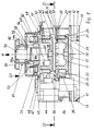
- the packet cam switch according to FIG. 1 has a base plate 10 on which a first intermediate plate or intermediate plate 15 can be locked or is locked in place in the embodiment according to FIG. 1 by means of locking lugs 11 and 12 which engage behind locking projections 13 and 14 on the base plate .
- the locking projections 11 and 12 are located on the intermediate plate 15 on one side;
- a circular projecting strip 16 is formed, in which a driving plate 17 is guided, on the side of which is opposite the intermediate plate 15, a cylindrical ring 18 is formed.
- the free ends of the cylindrical ring 18 are provided with radial grooves 19.
- the outer diameter of the cylindrical ring 18 is smaller than the outer diameter of the drive plate 17, so that between the outer circumference of the cylindrical ring 18 and the outer circumference of the drive plate 17, a guide surface 20 is formed, which has the same distance from the upper surface of the intermediate plate 15 as that End surface 21 of the ring 16.
- the cylindrical ring 18 is surrounded by a cam disc 22, the cam disc 22 sliding with its ring surface facing the base plate 10 on the surfaces 20 and 21.
- Radial grooves 25, which have different sections 26, 27 and 28, are provided on the radial surface of the cam disk 24 opposite the intermediate disk 15; the radially inner section 26 of the groove 25 is introduced in the axial direction as deep into the cam disk 22 as the grooves 19 of the driving disk 17; this is followed by the groove section 27, the depth of this section 27 being less than the depth of the section 26; the outer section 28 of the groove 25 has approximately the depth of the groove 26.
- a slide 29 is possibly guided against the pressure of a spring, not shown, which has 30 projections 31 and 32 at both ends of a central region; the projection 31 can now engage both in one of the grooves 19 and in the section 26.
- the slide 29 is in the normal position, its first position in which the projection 31 engages in the groove 19.
- the driving disk 17 is coupled to the cam disk 22.
- the slider 30 can be pulled outward in the direction of the arrow P by means of a handle extension 33, so that the projection 31 engages in the section 26 and the coupling between the driving plate 27 and the cam plate 22 is thus canceled.
- the slide 29 is in its second position in which it is also locked. Then the cam disk can be rotated in relation to the driving disk 17.
- the slide 29 is unlocked in its second position, in which the projection 32 is lifted out on the section 32 and the slide 29 is pushed inward into its first position.
- switch elements 34 On the base plate 10, on its left edge, switch elements 34 are provided which have a switching plunger 35 which engages with the cam region 24 of the cam disk 22. Another switching task of the switching elements 34 can be effected by pivoting the cam disc 22.
- second intermediate plate 36 which is similar to the first intermediate plate 15 and with which the unit consisting of intermediate plate 15, cam plate 22 and driving plate 17 is held together.
- the second intermediate plate 36 there is an identical configuration of the driving plate 40 with a cylindrical ring 40a corresponding to the ring 18 and a cam plate 41 with a corresponding slide 42.
- the second intermediate plate 36 has an annular strip 43 and no further illustrated locking lugs such as locking lugs 12, 11 of the intermediate disk 15.
- an end plate 45 is placed, which has a through opening 46 in the central area, on which the the unit 40, 41, 42 and 44 facing side there is a recess 47 which, in the assembled state, engages behind an edge 48 of a cover cap 49, in which a so-called catch star 50 is arranged, each with a spring 51 and 52 under the pressure radially inwardly pressed pin 53 and 54 cooperates.
- the locking star 50 has a recess 55 and an extension 56 which projects in the axial direction against the base plate 10. The section of the recess 55 with a larger diameter lies toward the base plate 10.
- a spring 57 projects into the interior of the recess 55 and is supported on the inner surface 58 of the drive plate 40 located within the cylindrical ring 40a and at the base of the recess 55, so that the locking star 50 is always pressed upward in the direction of arrow A.
- An actuating handle 59 protrudes from the cover cap 49, on the outer circumference of which pins 60 and 61 are formed on both sides. In the position shown in FIG. 1, the pins 60 and 61 are located outside the cover cap 49, so that the pins 53 and 54 cooperate with the lower section 55a.
- the pins 60 and 61 can get inside the cover cap 49 and are there by the cover cap 49 held so that the pins 53 and 54 cooperate with the upper portion 55b of the notch star 50.
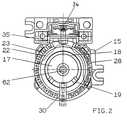
- Fig. 2 now shows a plan according to section line II-II.
- the cam disk 22 with the radial projection or radially projecting edge 23 and the sections 28 of the grooves 25 located on the cam disk 22 can be seen.
- the sections 28 indicated as grooves; the sections 27 and 26 are not grooves, but only depressions, so that when the slide 30 is pulled radially outward, both the extension 31 and the extension 32 are free of the corresponding grooves 28 and the grooves 19 of the driving ring 17th reached.
- the driver ring 17 Within the cam disk 22 there is the driver ring 17, the axially projecting ring 18 with the grooves 19 can be seen.
- a star-shaped opening 62 In the inside of the driver ring there is a star-shaped opening 62 through which a switching shaft (not shown in more detail) can reach in two positions.
- a switching shaft (not shown in more detail) can reach in two positions.
- d. H Next to the cam disc there is a switching element 34, the switching plunger 35 of which can engage the cam disc 22.
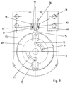
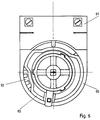
- FIG. 3 shows a top view according to arrow direction III.
- the top cover plate 45 can be seen in supervision.
- the cover cap 49 has two diametrically opposed slots 70, 71 in the form of quarter-circle arcs, concentric to its central axis, through which an adapted portion of the handle 59 can reach (not shown in FIG. 1).
- the handle 59 which has a plate area 59a and an area 59b projecting axially thereon, is inserted through this slot with two partial areas adapted to the slots 70, 71.
- the pins 60 and 61 can then be pressed inwards by slot areas 72 and 73 radially adjoining the slots 70, 71, so that the pins 60 and 61 are outside and inside the cover cap 49.
- the handle 59 can be rotated so that the pins 60 and 61 hold the handle 59 in its depressed position.
- the cover cap 49 can also be rotated, wherein it has radially extending corrugations or grooves 74 on the outside.
- a locking element 75 engages in these grooves 74, which is U-shaped with two legs 76 and 77, which engage in L-shaped guide elements 78 and 79.
- the outer surfaces of the legs 76 and 77 have lugs 80 and 81 which bear against retaining lugs 82 and 83 of the L-shaped legs 78 and 79.
- the locking element 75 is resilient in itself, so that after pressing the legs 76 and 77, the element 75 is released from the groove in which it has engaged; this allows the cap 49 to be rotated freely.
- the locking star 50 with its two sections 50a and 50b and the pins 53 and 54 cooperate with the areas 50a and 50b.
- the locking star 50 can now be used so that the pins 53 and 54 interact with the area 50a; an intermediate position is then obtained between two diametrically opposed cam projections 50c and 50d due to an intermediate recess 50e and 50f, whereas if the area 50b interacts with the pins 53 and 54, an automatic switching to another switching position is generated, since only four den Cams 50c and 50d corresponding cams 50g are provided.
- the switching device can be freely programmed on the one hand in the area of the detent star 50 and on the other hand by adjustment with the slide 30.
- the pins 53 and 54 are each formed on a slide element 63 which is guided radially in a guide device 64 integrally formed on the inside of the side wall of the cover cap 49 at diametrically opposite locations.
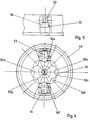
- a driver ring 92 and a cam disk 93 are provided in the same way as in the embodiment according to FIG. 1, a radially projecting arm 94 (FIG. 9) being integrally formed on the cam disk 93 which is resiliently formed by a slot 95 in the cam disk 93.
- a radially projecting arm 94 (FIG. 9) being integrally formed on the cam disk 93 which is resiliently formed by a slot 95 in the cam disk 93.
- an axially projecting cam 97 is molded, which can be coupled to the corresponding grooves 98 on the drive plate 92. If the arm 94 is pressed down with the cam 97 in the direction of arrow D (see FIG.
- the cam disk 93 has an opening 100 in the interior, which comprises a cylindrical projection 101 on the driving disk 92.
- the driving plate 92 has a projection 101 and a radial flange 102, on the edge of which, adjacent to the projection 101 or on the side, the grooves 98 are provided approximately uniformly distributed on the circumference.
- the driving plate 92 has a profiled through opening 103 in the center, through which a switching shaft, not shown, can reach.
- the drive plate 92 is actuated by the selector shaft and the cam plate via the projection 97, so that the switch or the switching element 81 can be actuated by means of the cam plate when the selector shaft is set in rotation.
- the driving ring 92 is placed on the base plate 90 or a suitable intermediate plate similar to the intermediate plate 15, and is guided as shown in FIG. 1, the radial rim 102 rests on the base plate 90 or the intermediate plate and is guided.
- the cam disk 93 is inserted over the cylindrical projection 101 in such a way that the nose 97 can engage in the grooves 98.
- an intermediate plate is again placed on this unit, as shown in FIG. 1, etc.
- the remaining individual parts are designed and connected as shown with reference to FIGS. 1 to 5.
Landscapes
- Multiple-Way Valves (AREA)
- Mechanisms For Operating Contacts (AREA)
- Transmission Devices (AREA)
Applications Claiming Priority (4)
| Application Number | Priority Date | Filing Date | Title |
|---|---|---|---|
| DE4340088 | 1993-11-24 | ||
| DE4340088 | 1993-11-24 | ||
| DE4440554 | 1994-11-12 | ||
| DE4440554A DE4440554B4 (de) | 1993-11-24 | 1994-11-12 | Paketnockenschalter |
Publications (3)
| Publication Number | Publication Date |
|---|---|
| EP0654807A2 true EP0654807A2 (fr) | 1995-05-24 |
| EP0654807A3 EP0654807A3 (fr) | 1997-04-23 |
| EP0654807B1 EP0654807B1 (fr) | 2000-05-03 |
Family
ID=25931502
Family Applications (1)
| Application Number | Title | Priority Date | Filing Date |
|---|---|---|---|
| EP19940118342 Expired - Lifetime EP0654807B1 (fr) | 1993-11-24 | 1994-11-22 | Interrupteur à cames étagé |
Country Status (2)
| Country | Link |
|---|---|
| EP (1) | EP0654807B1 (fr) |
| ES (1) | ES2147209T3 (fr) |
Family Cites Families (4)
| Publication number | Priority date | Publication date | Assignee | Title |
|---|---|---|---|---|
| FR565799A (fr) * | 1923-05-04 | 1924-02-04 | Gouy Et Lantier Ets | Mode général de construction et types de réalisation de contacts réglables |
| GB1004081A (en) * | 1960-12-02 | 1965-09-08 | Automatic Electrical Control C | Improvements relating to cam operated electric switches |
| DE1176236B (de) * | 1962-11-19 | 1964-08-20 | Reinhausen Maschf Scheubeck | Nockenschalteinrichtung |
| DE1765279A1 (de) * | 1968-04-26 | 1971-07-08 | Reinhausen Gebrueder Schaubeck | Nockenschalteinrichtung |
-
1994
- 1994-11-22 ES ES94118342T patent/ES2147209T3/es not_active Expired - Lifetime
- 1994-11-22 EP EP19940118342 patent/EP0654807B1/fr not_active Expired - Lifetime
Also Published As
| Publication number | Publication date |
|---|---|
| ES2147209T3 (es) | 2000-09-01 |
| EP0654807B1 (fr) | 2000-05-03 |
| EP0654807A3 (fr) | 1997-04-23 |
Similar Documents
| Publication | Publication Date | Title |
|---|---|---|
| DE2856720C3 (de) | Kupplung | |
| DE2948759C2 (fr) | ||
| DE4402599A1 (de) | Einrastmechanismus für eine automatische Getriebeschaltungssteuervorrichtung | |
| EP2505748A2 (fr) | Cylindre de serrage | |
| DE4325693C2 (de) | Türschließeinrichtung | |
| DE69907311T2 (de) | Axial entkuppelndes Schloss für ein Schlossmechanismus eines Personenkraftwagens | |
| EP0032555B1 (fr) | Mécanisme compteur ou imprimeur pour le comptage ou le numérotage consécutif | |
| DE2655540C2 (de) | "Zeitprogrammschalter, insbesondere für Wasch-, Spül- und Trockenmaschinen" | |
| DE3236531A1 (de) | Drehschalter, insbesondere fuer kraftfahrzeuge | |
| DE2845272C2 (de) | Zeitscheibe mit Schaltreitern für Schaltuhren | |
| EP0654807A2 (fr) | Interrupteur à cames étagé | |
| DE2046196C3 (de) | Kanalwähler mit Feinabstimmung | |
| EP1272078B1 (fr) | Robot de cuisine | |
| DE4440554B4 (de) | Paketnockenschalter | |
| EP1584512B1 (fr) | Disposition de composants, articulables entre eux et capables d'occuper au moins en deux endroits d'arrêt une position stable et définie au moyen d'un dispositif à cliquet | |
| EP0908640A1 (fr) | Dispositif de débrayage pour actionneur d'embrayage de véhicule | |
| DE69916481T2 (de) | Fahrzeugtürstelltrieb | |
| EP0647954B1 (fr) | Entraînement rotatif | |
| DE2461776C2 (de) | Demontierbare Nockenanordnung zur Betätigung von Schaltern | |
| DE19617988C2 (de) | Schaltvorrichtung mit Überschaltsperre | |
| DE2704898C2 (de) | Rasteinrichtung für Fernsehkanalwähler o.dgl. | |
| DE3046831A1 (de) | Elektrischer schalter, insbesondere druckknopfschalter | |
| EP0842822B1 (fr) | Bouton tournant. | |
| EP0913846B1 (fr) | Sélecteur avec thermostat pour four de cuisson | |
| EP2026146A2 (fr) | Disque de commutation pour un interrupteur horaire |
Legal Events
| Date | Code | Title | Description |
|---|---|---|---|
| PUAI | Public reference made under article 153(3) epc to a published international application that has entered the european phase |
Free format text: ORIGINAL CODE: 0009012 |
|
| AK | Designated contracting states |
Kind code of ref document: A2 Designated state(s): DE ES FR GB IT |
|
| RAP1 | Party data changed (applicant data changed or rights of an application transferred) |
Owner name: CEAG SICHERHEITSTECHNIK GMBH |
|
| PUAL | Search report despatched |
Free format text: ORIGINAL CODE: 0009013 |
|
| AK | Designated contracting states |
Kind code of ref document: A3 Designated state(s): DE ES FR GB IT |
|
| 17P | Request for examination filed |
Effective date: 19970613 |
|
| 17Q | First examination report despatched |
Effective date: 19980817 |
|
| GRAG | Despatch of communication of intention to grant |
Free format text: ORIGINAL CODE: EPIDOS AGRA |
|
| GRAG | Despatch of communication of intention to grant |
Free format text: ORIGINAL CODE: EPIDOS AGRA |
|
| GRAH | Despatch of communication of intention to grant a patent |
Free format text: ORIGINAL CODE: EPIDOS IGRA |
|
| GRAH | Despatch of communication of intention to grant a patent |
Free format text: ORIGINAL CODE: EPIDOS IGRA |
|
| GRAH | Despatch of communication of intention to grant a patent |
Free format text: ORIGINAL CODE: EPIDOS IGRA |
|
| GRAH | Despatch of communication of intention to grant a patent |
Free format text: ORIGINAL CODE: EPIDOS IGRA |
|
| GRAA | (expected) grant |
Free format text: ORIGINAL CODE: 0009210 |
|
| AK | Designated contracting states |
Kind code of ref document: B1 Designated state(s): DE ES FR GB IT |
|
| ITF | It: translation for a ep patent filed | ||
| GBT | Gb: translation of ep patent filed (gb section 77(6)(a)/1977) |
Effective date: 20000504 |
|
| REF | Corresponds to: |
Ref document number: 59409320 Country of ref document: DE Date of ref document: 20000608 |
|
| ET | Fr: translation filed | ||
| REG | Reference to a national code |
Ref country code: ES Ref legal event code: FG2A Ref document number: 2147209 Country of ref document: ES Kind code of ref document: T3 |
|
| PLBE | No opposition filed within time limit |
Free format text: ORIGINAL CODE: 0009261 |
|
| STAA | Information on the status of an ep patent application or granted ep patent |
Free format text: STATUS: NO OPPOSITION FILED WITHIN TIME LIMIT |
|
| 26N | No opposition filed | ||
| REG | Reference to a national code |
Ref country code: GB Ref legal event code: IF02 |
|
| PGFP | Annual fee paid to national office [announced via postgrant information from national office to epo] |
Ref country code: ES Payment date: 20021118 Year of fee payment: 9 |
|
| PG25 | Lapsed in a contracting state [announced via postgrant information from national office to epo] |
Ref country code: ES Free format text: LAPSE BECAUSE OF NON-PAYMENT OF DUE FEES Effective date: 20031124 |
|
| REG | Reference to a national code |
Ref country code: FR Ref legal event code: CD |
|
| REG | Reference to a national code |
Ref country code: ES Ref legal event code: FD2A Effective date: 20031124 |
|
| PGFP | Annual fee paid to national office [announced via postgrant information from national office to epo] |
Ref country code: DE Payment date: 20131129 Year of fee payment: 20 Ref country code: FR Payment date: 20131025 Year of fee payment: 20 Ref country code: GB Payment date: 20131028 Year of fee payment: 20 |
|
| PGFP | Annual fee paid to national office [announced via postgrant information from national office to epo] |
Ref country code: IT Payment date: 20131121 Year of fee payment: 20 |
|
| REG | Reference to a national code |
Ref country code: DE Ref legal event code: R071 Ref document number: 59409320 Country of ref document: DE |
|
| REG | Reference to a national code |
Ref country code: GB Ref legal event code: PE20 Expiry date: 20141121 |
|
| PG25 | Lapsed in a contracting state [announced via postgrant information from national office to epo] |
Ref country code: GB Free format text: LAPSE BECAUSE OF EXPIRATION OF PROTECTION Effective date: 20141121 |