EP0654807B1 - Paketnockenschalter - Google Patents
Paketnockenschalter Download PDFInfo
- Publication number
- EP0654807B1 EP0654807B1 EP19940118342 EP94118342A EP0654807B1 EP 0654807 B1 EP0654807 B1 EP 0654807B1 EP 19940118342 EP19940118342 EP 19940118342 EP 94118342 A EP94118342 A EP 94118342A EP 0654807 B1 EP0654807 B1 EP 0654807B1
- Authority
- EP
- European Patent Office
- Prior art keywords
- cam
- plate
- gang
- switch according
- latch
- Prior art date
- Legal status (The legal status is an assumption and is not a legal conclusion. Google has not performed a legal analysis and makes no representation as to the accuracy of the status listed.)
- Expired - Lifetime
Links
- 230000008878 coupling Effects 0.000 claims description 9
- 238000010168 coupling process Methods 0.000 claims description 9
- 238000005859 coupling reaction Methods 0.000 claims description 9
- 238000006073 displacement reaction Methods 0.000 claims 3
- 238000005452 bending Methods 0.000 claims 2
- 241001433879 Camarea Species 0.000 description 1
- 230000006835 compression Effects 0.000 description 1
- 238000007906 compression Methods 0.000 description 1
- 230000006378 damage Effects 0.000 description 1
- 230000004048 modification Effects 0.000 description 1
- 238000012986 modification Methods 0.000 description 1
Images


Classifications
-
- H—ELECTRICITY
- H01—ELECTRIC ELEMENTS
- H01H—ELECTRIC SWITCHES; RELAYS; SELECTORS; EMERGENCY PROTECTIVE DEVICES
- H01H19/00—Switches operated by an operating part which is rotatable about a longitudinal axis thereof and which is acted upon directly by a solid body external to the switch, e.g. by a hand
- H01H19/54—Switches operated by an operating part which is rotatable about a longitudinal axis thereof and which is acted upon directly by a solid body external to the switch, e.g. by a hand the operating part having at least five or an unspecified number of operative positions
- H01H19/60—Angularly-movable actuating part carrying no contacts
- H01H19/62—Contacts actuated by radial cams
- H01H19/623—Adjustable cams
Definitions
- the invention relates to a packet cam switch according to the preamble of claim 1.
- Package cam switches are known in a wide variety of designs become. They are on the axis of a selector shaft several cam disks, with the switching elements stacked on top of each other interact so that according to the switch position the shift shaft and the cam discs the desired switching elements be operated.
- a packet cam switch has become known from DE-AS 11 76 236, whose cam discs with respect to the selector shaft a worm wheel is also adjustable after assembly.
- a cam switch has become known from the generic DE-OS 17 65 279, whose cam disks are designed as a pair of cam disks and thereby a driving disk take between them using a pin on the drive shaft are set.
- the cam discs of each pair are resilient against the drive plate pressed.
- the positive connection of the cam discs with the drive plate is achieved by means of sprockets, and by means of a tool Adjustment of the cam discs can be made in the assembled state. Indeed this arrangement requires a lot of space because of the springs.
- a switching element in which two disks with one Shaft are rotatable. One disc is attached to the shaft and the other is relative to the others rotatably mounted on the shaft. Point to mutual adjustment Disks on their mutually facing sides toothing, which in different relative orientations of the disks can be brought into engagement with one another. At a Disc protrudes radially from an actuating element for a switching element.
- This actuator can for example be designed as a pin, as a cam or the like be and is provided on the disc rotatable relative to the shaft.
- the object of the invention is to provide a packet cam switch according to DE-OS 17 65 279 to improve a compact, pre-assembled unit with one setting of the individual switching operations even after the package cam switch has been assembled from pre-assembled units in a simplified manner.
- This task is in connection with the features of the preamble of the claim 1 solved by its characteristic features. It becomes a cam disc arrangement formed, via which the movement of the selector shaft on the switch contacts is transmitted.
- the cam disc assembly shows a follower ring or disc interacts directly with the selector shaft.
- the grips through the inner bore Shift shaft through. It is adapted to the outer profile shape of the selector shaft.
- the cam disc assembly continues to show the actual cam disc, with the driving ring in certain, desired positions by means of an adjustable in the pre-assembled Unit mounted actuator can be rotatably coupled. If you adjust the cam disc in relation to the drive ring and the control shaft, see above you can change a switching task afterwards and thus the packet cam switch to be provided with another program due to the axial stacking multiple units of cam and drive plate, with between each unit an intermediate plate is provided as a further part of the preassembled unit easy to assemble, pre-assembled units.
- a first development of the invention is the characterizing feature of the claim 2 can be seen.
- the coupling is thus carried out using a coupling slide as Actuator that is radially displaceable so that it is placed in two positions become can; in the first position it couples the drive ring and the cam disc and in a second position it decouples both so that they can be adjusted against each other.
- the coupling slide can be pulled outwards for decoupling and latches there, see claim 3, being his second Takes position; conversely, there is also the possibility form the coupling slide so that it counter to decoupling the pressure of a spring can be pressed radially inwards and locked.
- this solution is not optimal insofar as the Coupling slide then in the so-called rest position radially the cam disc can surpass.
- a strip is formed on the base plate according to claim 4, through which the drive plate is guided and centered.
- the cam disc can the ring of the drive plate include and thus the drive plate is used for guidance, in particular for rotating guidance and for centering the cam disc.
- a further embodiment of the invention can be designed in this way be as in the characterizing features of claim 6. According to the invention it simply becomes the springy arm bent as an actuator, so that the nose comes out of the corresponding recess, and twisted the cam disc so that the position between Driving ring and cam disc is changed; after snapping the projection or the nose into the corresponding other Locking recess is a positive connection of the driver ring and cam disc and thus a clutch from the selector shaft given to cam disc again.
- the rear derailleur can be a switch pot Have the shape of a cover cap and a detent star guided therein, wherein further on the cylindrical inner surface of the Switch pot at least one radially inwardly pressed Guide pin is provided on the outer surface of the notch star is pressed.
- the notch star can have at least two notch areas and be axially displaceable, so that the guide pin in one first axial position of the notch star with a first and in a second or third etc. axial position with the interact with the second or third etc. catch area of the catch star.
- the adjusting element can be an adjusting sleeve be one of the number of axial positions of the Rastensternes has a corresponding number of locking projections, the bayonet-like behind the bottom wall of the pot Switch pot are steerable.
- the switch pot can have recesses on the outer surface of the pot wall have, in which a locking element engages.
- the switch pot with the guide pins attached to it be rotatable after loosening the locking element.
- a particularly advantageous embodiment of the invention can thereby be characterized in that the base plate is formed is that it can be snapped onto a standard mounting rail.
- the cam disc with the Switch shaft and the driver ring a first assembly, which on the base plate is attached and to which the outer shape of the Base plate is adjusted; on the other side, next to the stack Cam stack, selector shaft and drive ring, the stack the switching elements attached to the base plate, and thereby it is achieved that the terminals only on one side the base plate are accessible.
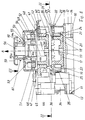
- the packet cam switch according to FIG. 1 has a base plate 10, on the by means of locking lugs 11 and 12, the locking projections behind 13 and 14 grip the base plate, a first intermediate plate or washer 15 can be locked or is locked in the embodiment according to FIG. 1.
- the locking tabs 11 and 12 are located at the intermediate disk 15 on one side; is on the opposite side a circular projecting ledge 16 is formed in which one Driving plate 17 is guided, on the intermediate plate 15th opposite side, a cylindrical ring 18 is formed.
- the free ends of the cylindrical ring 18 are radial Grooves 19 provided.
- the outer diameter of the cylindrical ring 18 is smaller than the outer diameter of the drive plate 17, so that between the outer periphery of the cylindrical ring 18 and a guide surface 20 on the outer circumference of the driving disk 17 formed by the upper surface of the washer 15 has the same distance as the end face 21 of the ring 16.
- the cylindrical ring 18 is surrounded by a cam disk 22, the cam disc 22 facing the base plate 10 Ring surface slides on surfaces 20 and 21.
- the Cam 22 has on the base plate 10 opposite lying side a circular radial projection 23, the projects beyond the cam areas 24.
- this groove 25 is possibly opposite the pressure of a spring, not shown, a slide 29 performed, the 30 projections at both ends of a central region 31 and 32; the projection 31 can now both in engage one of the grooves 19 as well as in the section 26.
- In 1 is the slide 29 in the normal position, its first position in which the projection 31 in the groove 19 engages.
- the driving plate 17 is included the cam disc 22 coupled.
- the slide can be used for decoupling 30 by means of a handle extension 33 to the outside in the direction of the arrow P are pulled so that the protrusion 31 in the section 26 engages and so the coupling between the drive plate 27 and the cam disc 22 is canceled.
- the slide 29 is located himself in his second position in which he also latches is. Then the cam plate can be related to the drive plate 17 are rotated. For coupling, the slide 29 in unlatched from its second position, in which the projection 32 on the section 32 lifted out and the slide 29 inwards one is pushed to its first position.
- switch elements 34 On the base plate 10, on its left edge are switch elements 34 provided, which have a switching plunger 35, the is in engagement with the cam region 24 of the cam disk 22. Another switching task can be performed by pivoting the cam disk 22 the switching elements 34 are effected.
- the same is located on the second intermediate disk 36 Design of drive plate 40 with a ring 18 corresponding cylindrical ring 40a and cam 41 with a corresponding slide 42.
- the second washer 36 has an annular in the same way as the washer 15 Bar 43 and not shown notches such as those locking lugs 12, 11 of the washer 15.
- the rim 48 of a cover cap 49 engages in a so-called catch star 50 is arranged with one spring under the pressure 51 and 52 cooperates radially inwardly pressed pins 53 and 54.
- the locking star 50 has a recess 55 and an extension 56 which is in the axial direction against the base plate 10 protrudes.
- the portion of the recess 55 with a larger one Diameter lies towards the base plate 10.
- a spring 57 which is on the inner surface located within the cylindrical ring 40a 58 of the driving plate 40 and on the base of the recess 55, so that the detent star 50 always in the direction of arrow A. is pressed at the top.
- An actuating handle protrudes from the cap 49 59 out, on the outer periphery pin 60 and 61 are integrally formed. Are in the position shown in Fig.
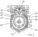
- Fig. 2 now shows a plan according to section line II-II.
- On the intermediate disc 15 shows the cam disc 22 with the radial projection or radially projecting edge 23 and the sections 28 of the grooves located on the cam disk 22 25.
- sections 28 are shown as Grooves indicated; sections 27 and 26 are not grooves, but only depressions, so that when the slide 30 is pulled out radially outwards, both the extension 31 as well as the extension 32 free of the corresponding grooves 28 or the grooves 19 of the driver ring 17 arrives.
- the driver ring is located within the cam disk 22 17, the axially projecting ring 18 with the grooves 19 can be seen is.
- d. H. is located next to the cam disc a switching element 34, the switching plunger 35 with the Cam disc 22 can engage.
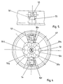
- FIG. 3 shows a top view according to arrow direction III.
- the cover cap 49 has two diametrically opposed ones concentric to its central axis Slots 70, 71 in the form of quarter arcs, through which an adapted portion of the handle 59 extends can (not shown in Fig. 1).
- the handle 59, the one plate portion 59a and one axially projecting thereon Has area 59b, with this from two to the Slots 70, 71 adapted sub-areas through this slot put through.
- the pins 60 and 61 can then by radial slot areas 72 and 73 adjoining the slots 70, 71 are pressed inwards so that the pins 60 and 61 one outside and the other inside the cap 49 are located.
- the handle 59 When the pegs 60 and 61 are inside the cap 49 are located, the handle 59 can be rotated so that the pins 60 and 61 pressed the handle 59 in its Hold your position.
- the cover cap can also be used 49 are rotated, being radial on the outside has running corrugations or grooves 74. In these grooves 74 engages a locking element 75 which is U-shaped with two Legs 76 and 77 is formed, which in L-shaped guide elements Intervene 78 and 79.
- the outer surfaces of the legs 76 and 77 have tabs 80 and 81 that hold tabs 82 and 83 of the L-shaped legs 78 and 79 abut.
- the locking element 75 is resilient in itself, so that after compression the leg 76 and 77 the element 75 is released from the groove, in which it intervened; this allows the cap 49 to be free be rotated.
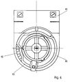
- the locking star 50 with its two sections 50a and 50b and the pins 53 and 54 act with the areas 50a and 50b together.
- the locking star 50 can now be used that the pins 53 and 54 cooperate with the area 50a; then you get between two diametrically opposed ones Cam projections 50c and 50d due to an intermediate recess 50e and 50f an intermediate position, whereas if the range 50b cooperates with the pins 53 and 54, an automatic Switching to another switching position is generated because only four correspond to cams 50c and 50d 50g cams are provided.
- the switching device can on the one hand in the area of the notch star 50 and on the other hand also by adjustment with the slide 30 can be freely programmed.
- the pins 53 and 54 are each formed on a slide element 63, that in one on the inside of the side wall of the cap 49 molded at diametrically opposite points Guide device 64 is guided radially.
- a driver ring 92 On a base plate 90 on which also switching elements 91 are housed in the same way as in the execution 1, a driver ring 92 is provided and a Cam disk 93, with a radially projecting on the cam disk 93 Arm 94 (Fig. 9) is integrally formed by a the slot 95 located cam 95 resilient is. On this arm 94 or in the resilient area 96 on which the arm 94 is formed radially outside the slot 45 an axially projecting cam 97 is formed, which with the corresponding Grooves 98 can be coupled to the drive plate 92.
- the arm 94 with the cam 97 in the direction of arrow D see Fig.
- the cam disc 93 has an opening 100 in the interior, one includes cylindrical projection 101 on the drive plate 92.
- the driving plate 92 has a projection 101 and a radial rim 102, on the edge of which Projection 101 adjacent or on the side, on the circumference the grooves 98 are provided approximately uniformly.
- the Driving plate 92 has a profiled through opening in the center 103, through which a not shown Can reach through the control shaft. The drive plate 92 will actuated by the selector shaft and via the projection 97 Cam disk so that the switch or the switching element 81 can be actuated when the switching shaft is rotated.
Landscapes
- Transmission Devices (AREA)
- Multiple-Way Valves (AREA)
- Mechanisms For Operating Contacts (AREA)
Description
- Fig. 1
- eine Schnittansicht durch eine erste Ausführungsform eines erfindungsgemäßen Paketnockenschalters,
- Fig. 2
- eine Aufsicht auf den Paketnockenschalter entsprechend Schnittlinie II-II,
- Fig. 3
- eine Aufsicht auf den Paketnockenschalter gemäß Pfeilrichtung III der Fig. 1,
- Fig. 4
- eine Einsicht in die obere Abdeckkappe,
- Fig. 5
- eine Schnittansicht gemäß Schnittlinie V-V der Fig. 4,
- Fig. 6
- eine weitere Ausgestaltung der Erfindung, im Bereich der Schnittlinie II-II der Fig. 1,
- Fig. 7
- eine Aufsicht auf eine Mitnehmerscheibe,
- Fig. 8
- eine Seitenansicht der Mitnehmerscheibe gemäß Fig. 4,
- Fig. 9
- eine Aufsicht auf die Nockenscheibe, die bei der Ausführung nach Fig. 6 Verwendung findet und
- Fig. 10
- eine Seitenansicht einer erfindungsgemäßen Nockenscheibe.
Claims (20)
- Paketnockenschalter mit einer Grundplatte (10), auf der wenigstens eine vormontierbare Einheit mit zumindest einer mit einer Schaltwelle gekuppelten Nockenscheibe (21, 22, 93) für jeweils ein Schaltelement und einer Mitnehmerscheibe (17, 40, 92) angeordnet ist, wobei die Nockenscheibe über die Mitnehmerscheibe mit einer Schaltwelle zur Betätigung jeweils eines Schaltelements drehfest form schlüssig gekuppelt ist,
dadurch gekennzeichnet,
daß in der vormontierbare Einheit zwischen jeder Nockenscheibe (21, 22, 93) und der Schaltwelle je eine Mitnehmerscheibe (17, 40, 92) geschaltet ist, die mit der Nockenscheibe in unterschiedlichen relativen Stellungen mittels eines verstellbar in der vormontierbaren Einheit gelagerten Betätigungselements (29, 42, 94) drehfest kuppelbar ist, wobei die Mitnehmer- und Nockenscheiben (17, 40; 21, 22) axial übereinander auf einer Zwischenscheibe (15) als weiterem Teil der vormontierbaren Einheit angeordnet sind. - Paketnockenschalter nach Anspruch 1, dadurch gekennzeichnet, daß die Mitnehmerscheibe (17, 40) einen axial vorspringenden, zylinderartigen Ring (18, 40a) aufweist, an dessen Stirnfläche am Umfang verteilte, radial verlaufende Mitnehmerscheibennuten (25) angebracht sind, daß die Nockenscheibe (22, 41) in bestimmten Stellungen mit den radialen Nuten (25) fluchtende, ebenfalls radial verlaufende Nockenscheibennuten (19) aufweist, und daß ein Koppelschieber (29) vorgesehen ist, der radial verschiebbar ist, so daß er in einer ersten Stellung in die Nuten (25, 19) sowohl der Nocken- als auch der Mitnehmerscheibe (17, 40) eingreift und in einer zweiten Stellung frei von den Nuten (19) der Mitnehmerscheibe (17, 40) ist, so daß die Nockenscheibe (22, 41) gegen die Mitnehmerscheibe (17, 40) verdrehbar ist.
- Paketnockenschalter nach Anspruch 2, dadurch gekennzeichnet, daß der Koppelschieber (29) radial nach außen ziehbar ist, wobei er in der inneren Ruhestellung (erste Stellung) die Nocken- und Mitnehmerscheibe (22, 41; 71, 40) miteinander kuppelt und in der herausgezogenen, zweiten Stellung freigibt bzw. umgekehrt.
- Paketnockenschalter nach Anspruch 2 oder 3, dadurch gekennzeichnet, daß an der Grundplatte (10) eine ringförmige, axial vorspringende Leiste (16) angeformt ist, in die Mitnehmerscheibe (17) eingreift und so geführt ist.
- Paketnockenschalter nach einem der vorherigen Ansprüche, dadurch gekennzeichnet, daß der zylindrische Ring (18, 40a) der Mitnehmerscheibe (22) von der Nockenscheibe (17, 41) umgeben ist und diese zentriert und führt.
- Paketnockenschalter nach Anspruch 1, dadurch gekennzeichnet, daß die Mitnehmerscheibe am Umfang verteilt angeordnete Rastausnehmungen (98) aufweist und daß an der in einer Ausnehmung der Mitnehmerscheibe (92) geführten Nockenscheibe (93) ein radial verlaufender, in axialer Richtung federnder, aufbiegbarer Arm (94) angeformt ist, an dem eine im Ruhezustand in eine der Rastausnehmungen (98) eingreifender Nocken (97) angebracht ist, der aus dieser Ausnehmung durch Verbiegung des Armes herausnehmbar und nach Verdrehung der Nockenscheibe (93) um einen bestimmten Winkelgrad in eine andere Rastausnehmung (98) wieder einrastbar ist.
- Paketnockenschalter nach einem der vorherigen Ansprüche, dadurch gekennzeichnet, daß auf die von der Grundplatte (10) am weitesten entfernte Einheit eine Endplatte (45) aufgelegt ist, die zur Halterung und Führung eines Schaltwerkes (50; 53, 54) dient.
- Paketnockenschalter nach einem der vorherigen Ansprüche, dadurch gekennzeichnet, daß die Schaltelemente (34, 44) auf der Grundplatte (10) auf einer Seite der Nockenscheibe (22...) übereinander gestapelt und damit deren Anschlußklemmen lediglich an einer Seite der Grundplatte (10) zugänglich sind.
- Paketnockenschalter nach einem der vorherigen Ansprüche, dadurch gekennzeichnet, daß die Nockenscheibe (22...) und die zugehörige Mitnehmerscheibe (17...) in axialer Richtung miteinander verrastet sind, so daß diese erst nach Lösung der Verrastung in axialer Richtung voneinander trennbar sind.
- Paketnockenschalter nach einem der vorherigen Ansprüche, dadurch gekennzeichnet, daß die Schaltelemente (33, 34) miteinander und das der Grundplatte (10) benachbarte Schaltelement (34) mit der Grundplatte (10) verrastet sind.
- Paketnockenschalter nach einem der vorherigen Ansprüche, dadurch gekennzeichnet, daß das Schaltwerk einen Schalttopf in Form einer Abdeckkappe (49) und einen darin geführten Rastenstern (50) aufweist.
- Paketnockenschalter nach Anspruch 11, dadurch gekennzeichnet, daß an der zylindrischen Innenfläche des Schalttopfes (49) wenigstens ein radial nach innen federnd gedrückter Führungszapfen (53, 54) vorgesehen ist, der auf die Außenfläche des Rastensterns (50) gedrückt ist.
- Paketnockenschalter nach einem der Ansprüche 11 und 12, dadurch gekennzeichnet, daß der Rastenstern (50) wenigstens zwei Rastenbereiche (50a, 50b) aufweist und axial verschiebbar ist, so daß die Führungszapfen (53, 54) in einer ersten axialen Stellung des Rastensternes (50) mit einer ersten und in einer zweiten oder dritten etc. axialen Stellung mit dem zweiten oder dritten etc. Rastenbereich des Rastensternes (50) zusammenwirken.
- Paketnockenschalter nach einem der Ansprüche 11 bis 13, dadurch gekennzeichnet, daß der Rastenstern (50) mittels eines Verstellelementes (56, 59) axial in die einzelnen Stellungen verbringbar ist.
- Paketnockenschalter nach Anspruch 13, dadurch gekennzeichnet, daß das Verstellelement (59) eine Verstellhülse ist, die eine der Anzahl der axialen Stellungen des Rastensternes entsprechende Anzahl von Feststellvorsprüngen (60, 61) aufweist, die bajonettverschlußartig hinter der Topfbodenwand des Schalttopfes (49) renkbar sind.
- Paketnockenschalter nach Anspruch 15, dadurch gekennzeichnet, daß der Schalttopf (49) an der Außenfläche der Topfwand Ausnehmungen (74) aufweist, in die ein Feststellelement (75) eingreift.
- Paketnockenschalter nach einem der Ansprüche 10 bis 16, dadurch gekennzeichnet, daß der Schalttopf (49) mit den daran angebrachten Führungszapfen (53, 54) nach Lösen des Feststellelementes (75) drehbar ist.
- Paketnockenschalter nach einem der vorherigen Ansprüche, dadurch gekennzeichnet, daß die Grundplatte (10) so ausgebildet ist, daß sie auf eine Normprofiltragschiene aufschnappbar ist.
- Paketnockenschalter nach einem der vorherigen Ansprüche, dadurch gekennzeichnet, daß an der Grundplatte (10) ein darin radial zu der Schaltwelle verschiebbarer und herausziehbarer Riegel vorgesehen ist, der mit der Schaltwelle form- und/oder kraftschlüssig zusammenwirkt und im eingeschobenen Zustand die Schaltwelle an der Grundplatte in axialer Richtung fixiert.
- Paketnockenschalter nach wenigstens einem der vorangehenden Ansprüche,
dadurch gekennzeichnet,
daß Rasteinrichtungen (11, 12) von der Zwischenscheibe (15, 36) abstehen und mit Grundplatte (10) oder einer bereits vormontierten Einheit in Rasteingriff bringbar sind.
Applications Claiming Priority (4)
| Application Number | Priority Date | Filing Date | Title |
|---|---|---|---|
| DE4340088 | 1993-11-24 | ||
| DE4340088 | 1993-11-24 | ||
| DE4440554 | 1994-11-12 | ||
| DE4440554A DE4440554B4 (de) | 1993-11-24 | 1994-11-12 | Paketnockenschalter |
Publications (3)
| Publication Number | Publication Date |
|---|---|
| EP0654807A2 EP0654807A2 (de) | 1995-05-24 |
| EP0654807A3 EP0654807A3 (de) | 1997-04-23 |
| EP0654807B1 true EP0654807B1 (de) | 2000-05-03 |
Family
ID=25931502
Family Applications (1)
| Application Number | Title | Priority Date | Filing Date |
|---|---|---|---|
| EP19940118342 Expired - Lifetime EP0654807B1 (de) | 1993-11-24 | 1994-11-22 | Paketnockenschalter |
Country Status (2)
| Country | Link |
|---|---|
| EP (1) | EP0654807B1 (de) |
| ES (1) | ES2147209T3 (de) |
Family Cites Families (4)
| Publication number | Priority date | Publication date | Assignee | Title |
|---|---|---|---|---|
| FR565799A (fr) * | 1923-05-04 | 1924-02-04 | Gouy Et Lantier Ets | Mode général de construction et types de réalisation de contacts réglables |
| GB1004081A (en) * | 1960-12-02 | 1965-09-08 | Automatic Electrical Control C | Improvements relating to cam operated electric switches |
| DE1176236B (de) * | 1962-11-19 | 1964-08-20 | Reinhausen Maschf Scheubeck | Nockenschalteinrichtung |
| DE1765279A1 (de) * | 1968-04-26 | 1971-07-08 | Reinhausen Gebrueder Schaubeck | Nockenschalteinrichtung |
-
1994
- 1994-11-22 ES ES94118342T patent/ES2147209T3/es not_active Expired - Lifetime
- 1994-11-22 EP EP19940118342 patent/EP0654807B1/de not_active Expired - Lifetime
Also Published As
| Publication number | Publication date |
|---|---|
| EP0654807A3 (de) | 1997-04-23 |
| ES2147209T3 (es) | 2000-09-01 |
| EP0654807A2 (de) | 1995-05-24 |
Similar Documents
| Publication | Publication Date | Title |
|---|---|---|
| EP0394556B1 (de) | Schaltvorrichtung für Wechselgetriebe von Kraftfahrzeugen | |
| DE4402599C2 (de) | Schaltvorrichtung für ein Automatikgetriebe mit einem Einrastmechanismus | |
| DE3030440C2 (de) | ||
| DE3834390C1 (de) | ||
| DE2856720C3 (de) | Kupplung | |
| DE2948759C2 (de) | ||
| DE2901639A1 (de) | Dampfdruckkochtopf | |
| DE4239552C1 (de) | Dampfdruckkochtopf | |
| EP0786162B1 (de) | Elektrische verbindungseinrichtung | |
| DE19935917B4 (de) | Wählhebelanordnung für ein Kraftfahrzeug | |
| EP0896921A1 (de) | Rastenschalter, insbesondere Drehgriffschalter zur Steuerung eines Fahrradgetriebes | |
| EP1121251B1 (de) | Achssicherung für die schwenkachse eines handstempels sowie handstempel | |
| EP0654807B1 (de) | Paketnockenschalter | |
| DE3236531A1 (de) | Drehschalter, insbesondere fuer kraftfahrzeuge | |
| DE2655540C2 (de) | "Zeitprogrammschalter, insbesondere für Wasch-, Spül- und Trockenmaschinen" | |
| DE3238660A1 (de) | Rastwerke, insbesondere fuer stufendrehschalter | |
| DE4440554B4 (de) | Paketnockenschalter | |
| DE2845272A1 (de) | Zeitscheibe mit schaltreitern fuer schaltuhren | |
| DE2824584C2 (de) | Mehrfach-Stufendrehschalter | |
| DE3431648C2 (de) | Permutationsschloß | |
| DE69916481T2 (de) | Fahrzeugtürstelltrieb | |
| DE2461776C2 (de) | Demontierbare Nockenanordnung zur Betätigung von Schaltern | |
| DE3333423A1 (de) | Mechanische schalteinrichtung | |
| DE19526051C1 (de) | Mehrteilige Nabe für eine Kupplungsscheibe | |
| DE3046831A1 (de) | Elektrischer schalter, insbesondere druckknopfschalter |
Legal Events
| Date | Code | Title | Description |
|---|---|---|---|
| PUAI | Public reference made under article 153(3) epc to a published international application that has entered the european phase |
Free format text: ORIGINAL CODE: 0009012 |
|
| AK | Designated contracting states |
Kind code of ref document: A2 Designated state(s): DE ES FR GB IT |
|
| RAP1 | Party data changed (applicant data changed or rights of an application transferred) |
Owner name: CEAG SICHERHEITSTECHNIK GMBH |
|
| PUAL | Search report despatched |
Free format text: ORIGINAL CODE: 0009013 |
|
| AK | Designated contracting states |
Kind code of ref document: A3 Designated state(s): DE ES FR GB IT |
|
| 17P | Request for examination filed |
Effective date: 19970613 |
|
| 17Q | First examination report despatched |
Effective date: 19980817 |
|
| GRAG | Despatch of communication of intention to grant |
Free format text: ORIGINAL CODE: EPIDOS AGRA |
|
| GRAG | Despatch of communication of intention to grant |
Free format text: ORIGINAL CODE: EPIDOS AGRA |
|
| GRAH | Despatch of communication of intention to grant a patent |
Free format text: ORIGINAL CODE: EPIDOS IGRA |
|
| GRAH | Despatch of communication of intention to grant a patent |
Free format text: ORIGINAL CODE: EPIDOS IGRA |
|
| GRAH | Despatch of communication of intention to grant a patent |
Free format text: ORIGINAL CODE: EPIDOS IGRA |
|
| GRAH | Despatch of communication of intention to grant a patent |
Free format text: ORIGINAL CODE: EPIDOS IGRA |
|
| GRAA | (expected) grant |
Free format text: ORIGINAL CODE: 0009210 |
|
| AK | Designated contracting states |
Kind code of ref document: B1 Designated state(s): DE ES FR GB IT |
|
| ITF | It: translation for a ep patent filed | ||
| GBT | Gb: translation of ep patent filed (gb section 77(6)(a)/1977) |
Effective date: 20000504 |
|
| REF | Corresponds to: |
Ref document number: 59409320 Country of ref document: DE Date of ref document: 20000608 |
|
| ET | Fr: translation filed | ||
| REG | Reference to a national code |
Ref country code: ES Ref legal event code: FG2A Ref document number: 2147209 Country of ref document: ES Kind code of ref document: T3 |
|
| PLBE | No opposition filed within time limit |
Free format text: ORIGINAL CODE: 0009261 |
|
| STAA | Information on the status of an ep patent application or granted ep patent |
Free format text: STATUS: NO OPPOSITION FILED WITHIN TIME LIMIT |
|
| 26N | No opposition filed | ||
| REG | Reference to a national code |
Ref country code: GB Ref legal event code: IF02 |
|
| PGFP | Annual fee paid to national office [announced via postgrant information from national office to epo] |
Ref country code: ES Payment date: 20021118 Year of fee payment: 9 |
|
| PG25 | Lapsed in a contracting state [announced via postgrant information from national office to epo] |
Ref country code: ES Free format text: LAPSE BECAUSE OF NON-PAYMENT OF DUE FEES Effective date: 20031124 |
|
| REG | Reference to a national code |
Ref country code: FR Ref legal event code: CD |
|
| REG | Reference to a national code |
Ref country code: ES Ref legal event code: FD2A Effective date: 20031124 |
|
| PGFP | Annual fee paid to national office [announced via postgrant information from national office to epo] |
Ref country code: DE Payment date: 20131129 Year of fee payment: 20 Ref country code: FR Payment date: 20131025 Year of fee payment: 20 Ref country code: GB Payment date: 20131028 Year of fee payment: 20 |
|
| PGFP | Annual fee paid to national office [announced via postgrant information from national office to epo] |
Ref country code: IT Payment date: 20131121 Year of fee payment: 20 |
|
| REG | Reference to a national code |
Ref country code: DE Ref legal event code: R071 Ref document number: 59409320 Country of ref document: DE |
|
| REG | Reference to a national code |
Ref country code: GB Ref legal event code: PE20 Expiry date: 20141121 |
|
| PG25 | Lapsed in a contracting state [announced via postgrant information from national office to epo] |
Ref country code: GB Free format text: LAPSE BECAUSE OF EXPIRATION OF PROTECTION Effective date: 20141121 |