EP0654819B2 - Verfahren zur Herstellung einer Anordnung zur Wärmeableitung - Google Patents
Verfahren zur Herstellung einer Anordnung zur Wärmeableitung Download PDFInfo
- Publication number
- EP0654819B2 EP0654819B2 EP94250278A EP94250278A EP0654819B2 EP 0654819 B2 EP0654819 B2 EP 0654819B2 EP 94250278 A EP94250278 A EP 94250278A EP 94250278 A EP94250278 A EP 94250278A EP 0654819 B2 EP0654819 B2 EP 0654819B2
- Authority
- EP
- European Patent Office
- Prior art keywords
- heat
- housing
- moulding
- jet
- circuit component
- Prior art date
- Legal status (The legal status is an assumption and is not a legal conclusion. Google has not performed a legal analysis and makes no representation as to the accuracy of the status listed.)
- Expired - Lifetime
Links
Images


Classifications
-
- H—ELECTRICITY
- H10—SEMICONDUCTOR DEVICES; ELECTRIC SOLID-STATE DEVICES NOT OTHERWISE PROVIDED FOR
- H10W—GENERIC PACKAGES, INTERCONNECTIONS, CONNECTORS OR OTHER CONSTRUCTIONAL DETAILS OF DEVICES COVERED BY CLASS H10
- H10W40/00—Arrangements for thermal protection or thermal control
- H10W40/40—Arrangements for thermal protection or thermal control involving heat exchange by flowing fluids
- H10W40/43—Arrangements for thermal protection or thermal control involving heat exchange by flowing fluids by flowing gases, e.g. forced air cooling
-
- H—ELECTRICITY
- H10—SEMICONDUCTOR DEVICES; ELECTRIC SOLID-STATE DEVICES NOT OTHERWISE PROVIDED FOR
- H10W—GENERIC PACKAGES, INTERCONNECTIONS, CONNECTORS OR OTHER CONSTRUCTIONAL DETAILS OF DEVICES COVERED BY CLASS H10
- H10W40/00—Arrangements for thermal protection or thermal control
- H10W40/70—Fillings or auxiliary members in containers or in encapsulations for thermal protection or control
- H10W40/77—Auxiliary members characterised by their shape
Definitions
- the invention relates to a method in Preamble of claims 1 and 2 specified type.
- mica flakes is known or thermal paste - such as silicone paste Alumina admixture - for this purpose.
- the invention is therefore based on the object an improved method of making a Heat dissipation arrangement of the type mentioned specify.
- the invention includes the idea of Process for the production of an arrangement for heat dissipation including the component to be cooled or specify the module in which the heat transfer funds that promote the environment technologically advanced way stranded immediately on the component or assembly to be cooled or generated a separate heat sink or may even be trained so that it functions as a Take over the heat sink, so that such a whole can be omitted.
- it can also be thermally conductive elastic structures are generated, which is a mushroom-like Contour (or its negative image) and with conventional molding agents (also by extrusion) could not be easily generated. This allows electronic components, for example without additional fastenings by "buttoning" be connected with a bracket.
- a second possibility is to create one formed separately from the component or assembly Heat diffuser (heat sink) - as that too an already required carrier or one or more External housing enclosing components or assemblies (in part) can serve - with one directly the surface of which is formed thermally conductive plastic moldings, the at least in the operation of the component or the assembly in contact with its or whose surface is standing.
- the heat diffuser can in particular by screwing or pressing firmly be connected to the component or assembly or can be releasably pressed against this - for example by appropriate Moving and locking a movable Housing part.
- the plastic molded body elastically deformable at least in sections or is formed compressible so that by mediating a intimate surface contact of component or group and heat diffuser under appropriate contact pressure a very low heat transfer resistance reached and, if necessary, a seal (e.g. of an outer housing interior to the outside) can be.
- a seal e.g. of an outer housing interior to the outside
- Due to the elastic or compressible Design of the molded body will be in particular Tolerances between the outer housing and component housing balanced so that one half of the housing, in which the components or assemblies to be cooled are pre-assembled by simply closing them with the other half of the housing without any special additional measures can be thermally contacted can.
- This handling is particularly important for the assemblies of microelectronics and miniaturized housings - such as hand-held radio telephones from special meaning.
- the compressible thermally conductive Plastic material is applied in particular in such a way that essentially in the direction of heat transfer directed spaces provided are, which up to a maximum compression - in provided tolerance range - pick up material can when the housing is assembled.
- the invention includes the realization that improvement of the thermal contact due to the clinging Areas of the elastic heat sink larger as a result of increase in thermal resistance the conductive reduced by the recesses Section.
- the component or Assembly and the heat diffuser each have a molded plastic body with at least one free surface each have and the free surfaces of these plastic moldings are facing each other and at least in the operating state of the component or assembly in Are in contact with each other.
- the molded plastic body is specially made by Dispensing plastic material in plasticized Condition on a surface of the component or assembly and on-site curing of the material educated.
- the plastic molded body from a room temperature cross-linking or setting plastic with thermally conductive admixture, so that it without complex heating of the arrangement can be formed can.
- thermally conductive admixtures for example electrically non-conductive metal connections (Boron nitride, aluminum oxide) used in powder form. Has the component or assembly an electrical insulating sheath come on, too electrically conductive admixtures, such as metal powder, in Question.
- a simple and mechanically stable arrangement with sections of relatively thick molded plastic body - such as when using a mobile, with a seal to be provided as a housing part Heat diffuser may be required - if the plastic molding at least in some areas is produced in multiple layers, each layer on the spot below and with this adherent bond is formed.
- Such training is also beneficial in Connection with further training, in which the Plastic molded body pimples or rib-like elevations having its surface and / or its Increase elasticity and thus the heat conduction properties improve. It enables education relatively high pimples or ribs with sufficient precisely definable shape and sufficient mechanical Stability.
- the properties of the arrangement in particular under changing contact pressures still improve that the pimpled or rib-like Elevations of the molded plastic body adjacent Recesses provided in the molded plastic body are into which a deformation of the Plastic molded body at least parts of the surveys extend.
- knobs or ribs are specific to the adjacent one Surface (of the molded plastic body or also - with direct formation of individual knobs or ribs on the component, the assembly or the Heatsink - on its surface) are formed, they lie down when pressing the other part to the side in the adjacent recess and thus form a largely compact and in good contact with both neighboring surfaces standing heat transfer layer.
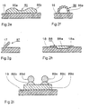
- Fig. 1 is an aluminum housing 1 as a thermal Diffuser for an electronic circuit assembly 2, which are electrically isolated on a at the same time serving as the cover of the housing 4 is attached.
- the housing 1 is intended both for protection and also serve to cool the circuit assembly 2. It has a recess 3 for inserting the Circuit assembly on the 4 with the carrier
- the module is closed by a hinge 4a after folding becomes. Ribs 4b provided in the housing and 4c, which are in the closed state of the housing Contact the carrier 4 are used for improved Heat dissipation.
- the cylinder 5b of the device 5 is with a drying in air and room temperature pasty silicone polymers 8 'with embedded metal particles filled that under that exerted on the piston 5a Pressure through the cannula 6a of the needle 6 on the Housing surface is pressed on ("dispensed"), adheres there and under air access to an elastic Plastic profile 8 hardens.
- the (cross-sectional) dimensions and shape of the plastic profile 8 are still due to the physicochemical Properties of the thermally conductive used Plastic mass - especially their Curing speed, viscosity, surface tension regarding the housing material and thixotropy -, through the cross-section of the cannula, on the Piston pressure, the speed of needle movement as well as environmental influences such as Temperature and humidity determined at the place of manufacture and are therefore by appropriate choice of these parameters can also be specified.
- Setting the properties of the plastic mass can in particular by adding of fillers (soot or similar), metal binders, Surfactants and curing accelerators or cross-linking agents respectively.
- thermal conductivity securing admixture - for electrically insulating Plastic moldings such as boron nitride or aluminum oxide particles
- electrically conductive Plastic moldings such as carbon, silver, with silver or gold coated copper particles or similar - influenced not only the thermal, but also the mechanical, electrical and processing properties of the thermally conductive elastic material.
- Figure 1a is the device for application of the conductive and elastic plastic material in Play strand shape again in section and enlarged. Otherwise, the same applies with regard to figure 1 used reference numerals.
- an electronic component 210 is a plastic encapsulated integrated Circuit reproduced on the strand-like Thermal coupling elements 8d generated for heat dissipation become.
- FIGS. 2a to k are different Profile cross-sections shown by means of inventive method when providing several Order steps have prepared arrangements can, in which the plastic molded body is essentially extends in one direction, i.e. an artistic profile represents.
- Figs. 2a to 2d are good heat conductors, less elastic sealing parts (hatched shown) with non-conductive, due to the missing Addition of thermally conductive material more elastic Sealing parts combined, creating an optimal Combination of sealing and heat transfer effects is achieved.
- Figures 2a to 2i are examples of the Design by different nozzle shapes Generatable strand-shaped heat transfer Profiled bodies reproduced, which in part by sequential application of various Extruded profiles were created one after the other. In this way, elastic thermally conductive Create bodies of any (even non-demouldable) contour, which also include hollow chambers, for example can.
- FIG. 2a shows in particular one in two Order steps side by side on the surface of a Profiled parts 81 and 82 formed with an approximately circular cross-section Heat transfer and seal construction. On such structure arises when the elastic material the surface of the case is slightly wet.
- FIG. 2b shows one generated in three steps Profile structure made of a flat curved, wide conductive Profile part 82a and a "dispensed" onto this conductive part 82c and a non-conductive Part 82b on a housing section 12, the parts 82b and 82c have an approximately circular cross section.
- Such a structure arises when the material of the first profile part 82a is the surface of the housing heavily wetted and / or its order with a relatively wide nozzle instead of the needle shown in Fig. 2 6 was done while the material of parts 82b and 82c low tendency to wet the surface of part 82a.
- FIG. 2c shows a structure similar to FIG. 2b, but on both sides one on a lower one, wide profile part 83a on a housing surface 13 centrally located, but not elastic conductive, almost semicircular sealing profile 83d two also approximately semicircular, highly thermally conductive Profile parts 83b and 83c were arranged.
- This latter profile shows great stability towards acting parallel to the housing surface Forces, but has a comparatively low overall Elasticity. It can be used for sliding closures be particularly suitable.
- the figures 2e to 2i show plastic moldings, which consist exclusively of thermally conductive material.
- Fig. 2e shows a specially shaped one-piece Profile 85 on a housing surface 15, the two beads 85a and 85 connected by a flat web having.
- a profile can be used for housings with edge profiles Folding closures may be appropriate.
- Fig. 2f shows one of several circular Profile strands in total semicircular Plastic profile 86 on a housing surface 16, the with this encloses an air space 86a.
- 2h is a T-shaped profile 88 on one a rectangular groove 18a housing surface 18, which has a wide central part 88a engages in the groove 18a and overall a plane to Housing surface 18 outside the groove 18a parallel Surface.
- This profile is with the case surface not only materially but also positively connected, which further increases stability.
- Fig. 2i is a profile structure from an approximation rectangular cross-section block 89a made of conductive, elastic material and two on it juxtaposed, flat arched profile parts 89b and 89c shown by its large Cross section especially for the transfer of large amounts of heat is suitable, but through the patch Sealing lips 89b and 89c also have sufficient elasticity having.
- Fig. 3 shows schematically an electronic Assembly 211 with in the manner shown in Fig. 1 andispensertem plastic heatsink 811, which is made in several strand formation steps in layers individually applied to the surface of the assembly There are cooling fins.
- Such an arrangement can for example with electronic devices in the mobile Use (radio equipment, mobile phone or similar) find application.
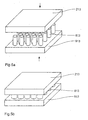
- FIG. 4a schematically shows an electronic one Assembly 212 with molded-on thermally conductive Plastic molded body 812a, which is wavy in cross section Has surface and with a ribbed Heat sink 912 is connected as a heat diffuser, a second molded plastic body on its flat surface 812b is integrally formed. Its surface shows the same structure as that of the first molded plastic body 812a, but it is laterally opposite this applied somewhat offset, so that the elevations on one body each in depressions of the other both bodies intervene due to their elasticity when assembly 212 and heat sink are pressed together 912 an almost homogeneous heat transfer layer form.
- FIG. 4b shows a sectional illustration, like an electronic component 215 in one on an active fan element 915 as a heat diffuser acting body with an elastic is provided heat-conducting structure 815, thereby "Buttonable” is that the transverse extension of the structure also at an increasing distance from their base increases.
- the sectional view shown in the figure corresponds to a vertical sectional view in a direction perpendicular thereto so that a collar area 815a the inserted component 215 on a ring-shaped closed line secures against falling out.
- a similar final state is shown schematically with the in fig. 5a and 5b reached arrangement, one assembly 213 via an array 813 from individual, highly elastic plastic knobs, the is applied to a heat sink 913, with this is connected.
- Assembly 213 and heat sink 913 become the knobs or islands of the array 813 compressed in height, with what their cross section increases and they essentially the space between the assembly and fill the heat sink and for good heat transfer to care.
- FIG. 6a and 6b show a further embodiment, where one assembly 214 and one ribbed Heatsink 914 with each other via a hinge 914a be connected, with the heat sink on its non-ribbed surface a molded plastic body 814 with inclined ribs.
- Fig. 6b shows in the final state - the ribs of the plastic molded body 814 unidirectionally in the each adjacent space. In this way creates a largely homogeneous, with the adjacent Heat transfer bodies in close contact with surfaces between assembly and heat sink.
- the invention is limited in its execution not on the above-mentioned embodiments. Rather, there are a number of variations conceivable. These include, in particular, orders for Heat transfer outside the area of the Electronics, for example in measuring, heating, cooling and air conditioning technology.
Landscapes
- Cooling Or The Like Of Electrical Apparatus (AREA)
- Cooling Or The Like Of Semiconductors Or Solid State Devices (AREA)
- Structures Or Materials For Encapsulating Or Coating Semiconductor Devices Or Solid State Devices (AREA)
- Heating, Cooling, Or Curing Plastics Or The Like In General (AREA)
- Re-Forming, After-Treatment, Cutting And Transporting Of Glass Products (AREA)
- Auxiliary Devices For And Details Of Packaging Control (AREA)
- Non-Silver Salt Photosensitive Materials And Non-Silver Salt Photography (AREA)
- Encapsulation Of And Coatings For Semiconductor Or Solid State Devices (AREA)
Description
Claims (6)
- Verfahren zur Herstellung einer Anordnung zur Ableitung von Wärme vom Gehäuse eines elektronischen, Verlustwärme erzeugenden, mit einem unmittelbar auf der Oberfläche eines mit dem Gehäuse des Schaltungsbauteils oder einer entsprechenden Baugruppe wärmeleitend verbundenen zusätzlichen Wärmediffusors angeordneten, getrennt gebildeten Formkörper zwischen Gehäuse des Schaltungsbauteils oder einer entsprechenden Baugruppe and Wärmediffusor (811; 812a) aus wärmeleitendem Kunststoff, den Wärmediffusor (1, 1'; 11 bis 14; 912 bis 914) flächig kontaktiert und mindestens bereichsweise elastisch verformbar oder kompressibel ist,
dadurch gekennzeichnet, daß Kunststoffmaterial (8') in plastischem Zustand unter Druck aus einem Vorratsbehälter durch eine Hohlnadel (6) bzw. Düse in Form eines Strangs mit einer Querschnittsform, die dem Innenquerschnitt der Düse oder Hohlnadel im wesentlichen entsprucht, unmittelbar auf einen Bereich (3a) des Wärmediffusors, auf dem der Formkörper (8) gebildet werden soll, durch Dispensieren aufgebracht und nach dem Aufbringen unter Beibehaltung der Querschnittsform zu einem entsprechenden elastischen Körper gehärtet bzw. vernetzt wird. - Verfahren zur Herstellung einer Anordnung zur Ableitung von Wärme vom Gehäuse eines elektronischen, Verlustwärme erzeugenden, mit einem auf der Oberfläche des Gehäuses des Schaltungsbauteils oder einer entsprechenden Baugruppe (2, 211 bis 214) angeordneten, getrennt gebildeten Formkörper (811; 812a) aus wärmeleitendem Kunststoff, der das Gehäuse des Schaltungsbauteils oder einer entsprechenden Baugruppe flächig kontaktiert und mindestens bereichsweise elastisch verformbar oder kompressibel ist,
dadurch gekennzeichnet, daß Kunststoffmaterial (8') in plastischem Zustand unter Druck aus einem Vorratsbehälter durch eine Hohlnadel (6) bzw. Düse in Form eines Strangs mit einer Querschnittsform, die dem Innenquerschnitt der Düse oder Hohlnadel im wesentlichen entsprucht, unmittelbar auf einen Bereich (3a) des Gehäuses des Schaltungsbauteils oder einer entsprechenden Baugruppe, auf dem der Formkörper (8) gebildet werden soll, durch Dispensieren aufgebracht und nach dem Aufbringen unter Beibehaltung der Querschnittsform zu einem entsprechenden elastischen Körper gehärtet bzw. vernetzt wird. - Verfahren nach Anspruch 1 oder 2, dadurch gekennzeichnet, daß die Hohlnadel (6) bzw. Düse durch Antriebsmittel, insbesondere rechnergesteuert, auf einem vorgegebenen Weg über den Bereich (3a) des Teils (1), an dem der Formkörper (8) erzeugt werden soll, geführt wird.
- Verfahren nach Anspruch 1, 2 oder 3 dadurch gekennzeichnet, daß zur Herstellung eines mehrschichtigen Formkörpers (8) die Nadel (6) bzw. Düse mindestens über vorbestimmte Abschnitte des Bereiches (3a), an dem der Formkörper erzeugt werden soll, mehrfach derart geführt wird, daß sich aus mehreren Strängen des Kunststoffmaterials (8') eine vorgegebene Gestalt des Formkörpers aufbaut, wobei ein nachfolgender Strang vor dem Aushärten bzw. Vernetzen der Oberfläche des vorangehenden Strangs aufgebracht wird, so daß beide Stränge sich nach dem Aushärten oder Vernetzen materialkonform verbinden.
- Verfahren nach Anspruch 4, dadurch gekennzeichnet, daß beim mehrfachen Führen der Nadel (6) bzw. Düse über die vorbestimmten Bereiche unterschiedlich elastisch oder unterschiedlich kompressibel aushärtende Kunststoffmaterialien aufgebracht werden.
- Verfahren nach einem der Ansprüche 1 bis 5, dadurch gekennzeichnet, daß das Aufbringen des plastischen Kunststoffmaterials bei Raumtemperatur erfolgt.
Applications Claiming Priority (2)
| Application Number | Priority Date | Filing Date | Title |
|---|---|---|---|
| DE4339786A DE4339786C5 (de) | 1993-11-18 | 1993-11-18 | Verfahren zur Herstellung einer Anordung zur Wärmeableitung |
| DE4339786 | 1993-11-18 |
Publications (4)
| Publication Number | Publication Date |
|---|---|
| EP0654819A2 EP0654819A2 (de) | 1995-05-24 |
| EP0654819A3 EP0654819A3 (de) | 1995-10-18 |
| EP0654819B1 EP0654819B1 (de) | 1999-02-03 |
| EP0654819B2 true EP0654819B2 (de) | 2004-11-24 |
Family
ID=6503161
Family Applications (1)
| Application Number | Title | Priority Date | Filing Date |
|---|---|---|---|
| EP94250278A Expired - Lifetime EP0654819B2 (de) | 1993-11-18 | 1994-11-17 | Verfahren zur Herstellung einer Anordnung zur Wärmeableitung |
Country Status (9)
| Country | Link |
|---|---|
| US (1) | US5518758A (de) |
| EP (1) | EP0654819B2 (de) |
| JP (1) | JP3364027B2 (de) |
| CN (1) | CN1057188C (de) |
| AT (1) | ATE176551T1 (de) |
| AU (1) | AU675176B2 (de) |
| DE (2) | DE4339786C5 (de) |
| DK (1) | DK0654819T3 (de) |
| RU (1) | RU2152697C1 (de) |
Families Citing this family (50)
| Publication number | Priority date | Publication date | Assignee | Title |
|---|---|---|---|---|
| US5781412A (en) * | 1996-11-22 | 1998-07-14 | Parker-Hannifin Corporation | Conductive cooling of a heat-generating electronic component using a cured-in-place, thermally-conductive interlayer having a filler of controlled particle size |
| DE19739591A1 (de) * | 1997-09-10 | 1999-03-11 | Wuerth Elektronik Gmbh & Co Kg | Recyclingfähige Leiterplatte, bestehend aus einem Folien- und Trägersystem |
| JPH11186003A (ja) * | 1997-12-25 | 1999-07-09 | Yazaki Corp | Ptc素子の放熱構造 |
| DE19836229C1 (de) | 1998-08-04 | 2000-03-23 | Hielscher Gmbh | Anordnung zur Wärmeableitung, insbesondere für Ultraschallwandler mit hoher Leistung |
| DE19952768A1 (de) * | 1999-11-02 | 2001-05-31 | Wincor Nixdorf Gmbh & Co Kg | Vorrichtung zum thermischen Verbinden eines elektronischen Bauelementes mit einem Kühlkörper |
| DE19959985A1 (de) * | 1999-12-13 | 2001-07-05 | Tyco Electronics Logistics Ag | Elektronischer Trennschalter |
| DE10013844A1 (de) * | 2000-03-15 | 2001-09-27 | Infineon Technologies Ag | Vorrichtung zum Kühlen eines elektrischen Moduls |
| DE10038161A1 (de) * | 2000-08-04 | 2002-02-21 | Infineon Technologies Ag | Kühlvorrichtung für elektronische Bauteile und Verfahren zur Herstellung der Kühlvorrichtung |
| DE20019053U1 (de) | 2000-11-09 | 2001-02-08 | Robert Bosch Gmbh, 70469 Stuttgart | Kühlkörper-Leiterbahnen-Anordnung |
| DE10106346B4 (de) * | 2001-02-09 | 2007-03-01 | Infineon Technologies Ag | Elektronisches Bauteil |
| DE10109083B4 (de) * | 2001-02-24 | 2006-07-13 | Conti Temic Microelectronic Gmbh | Elektronische Baugruppe |
| JP4796704B2 (ja) * | 2001-03-30 | 2011-10-19 | 株式会社タイカ | 押出可能な架橋済グリース状放熱材を充填・封入した容器の製法 |
| JP3713706B2 (ja) * | 2001-09-28 | 2005-11-09 | 日本電気株式会社 | 放熱構造、パッケージ組立体、及び、放熱用シート |
| WO2003030610A1 (en) | 2001-10-02 | 2003-04-10 | Parker Hannifin Corporation | Emi shielding gasket construction |
| TW591363B (en) * | 2001-10-10 | 2004-06-11 | Aavid Thermalloy Llc | Heat collector with mounting plate |
| KR100652621B1 (ko) | 2003-11-21 | 2006-12-06 | 엘지전자 주식회사 | 휴대용 단말기의 방열장치 |
| DE102004040596A1 (de) * | 2004-08-21 | 2006-02-23 | Robert Bosch Gmbh | Elektrische Vorrichtung mit einem Gehäuse und einem Kühlkörper |
| KR100684751B1 (ko) * | 2004-11-17 | 2007-02-20 | 삼성에스디아이 주식회사 | 플라즈마 디스플레이 장치 |
| FR2886509B1 (fr) | 2005-05-24 | 2007-09-14 | Thales Sa | Dispositif electronique modulaire fonctionnant dans des environnements severes |
| RU2302091C2 (ru) * | 2005-08-15 | 2007-06-27 | Федеральное агентство по атомной энергии | Устройство для защиты от механических воздействий |
| US7828424B2 (en) * | 2006-05-19 | 2010-11-09 | Xerox Corporation | Heater and drip plate for ink loader melt assembly |
| JP4741999B2 (ja) * | 2006-09-07 | 2011-08-10 | 日本電気株式会社 | 放熱装置および無線機 |
| US7728219B2 (en) * | 2006-12-11 | 2010-06-01 | Sunmodular, Inc. | Photovoltaic cells, modules and methods of making same |
| US8410350B2 (en) | 2006-12-11 | 2013-04-02 | Ns Acquisition Llc | Modular solar panels with heat exchange |
| DE102007014713B3 (de) * | 2007-03-23 | 2008-09-18 | Sew-Eurodrive Gmbh & Co. Kg | Kühlanordnung, Umrichter und elektrisches Antriebssystem |
| WO2008137966A2 (en) | 2007-05-07 | 2008-11-13 | Robert Stancel | Structures for low cost, reliable solar roofing |
| US7764504B2 (en) * | 2007-05-16 | 2010-07-27 | Tyco Electronics Corporation | Heat transfer system for a receptacle assembly |
| US8216418B2 (en) * | 2007-06-13 | 2012-07-10 | Lam Research Corporation | Electrode assembly and plasma processing chamber utilizing thermally conductive gasket and o-rings |
| US8152954B2 (en) * | 2007-10-12 | 2012-04-10 | Lam Research Corporation | Showerhead electrode assemblies and plasma processing chambers incorporating the same |
| US8187414B2 (en) * | 2007-10-12 | 2012-05-29 | Lam Research Corporation | Anchoring inserts, electrode assemblies, and plasma processing chambers |
| RU2350055C1 (ru) * | 2008-01-29 | 2009-03-20 | Евгений Эдуардович Горохов-Мирошников | Модуль, состоящий из подложки, силовых приборов, электрической схемы и теплоотвода |
| US8187413B2 (en) * | 2008-03-18 | 2012-05-29 | Lam Research Corporation | Electrode assembly and plasma processing chamber utilizing thermally conductive gasket |
| US8679288B2 (en) | 2008-06-09 | 2014-03-25 | Lam Research Corporation | Showerhead electrode assemblies for plasma processing apparatuses |
| DE102008028611B4 (de) * | 2008-06-18 | 2012-11-08 | Phoenix Contact Gmbh & Co. Kg | Leuchtelement mit Kunststoffhalterung |
| US8449679B2 (en) | 2008-08-15 | 2013-05-28 | Lam Research Corporation | Temperature controlled hot edge ring assembly |
| DE102009045915A1 (de) | 2009-10-22 | 2011-04-28 | Robert Bosch Gmbh | Toleranzfreie Leiterplattenklemmung |
| JP2011155118A (ja) * | 2010-01-27 | 2011-08-11 | Hitachi Ltd | ヒートシンク取付体およびヒートシンク取付け方法 |
| RU2451436C1 (ru) * | 2011-03-31 | 2012-05-20 | ОБЩЕСТВО С ОГРАНИЧЕННОЙ ОТВЕТСТВЕННОСТЬЮ "МикроМакс Системс" | Способ и устройство для отвода тепла |
| WO2013025130A1 (ru) * | 2011-08-18 | 2013-02-21 | Общество С Ограниченной Ответственностью "Прорывные Инновационные Технологии" | Теплоотводящее устройство |
| US9417017B2 (en) | 2012-03-20 | 2016-08-16 | Thermal Corp. | Heat transfer apparatus and method |
| DE102012207790A1 (de) * | 2012-05-10 | 2013-11-14 | Kuhnke Automotive Gmbh & Co. Kg | Elektrische Schaltungseinheit |
| RU2513038C1 (ru) * | 2012-08-27 | 2014-04-20 | Открытое акционерное общество Арзамасское научно-производственное предприятие "ТЕМП-АВИА" (ОАО АНПП "ТЕМП-АВИА") | Радиоэлектронный блок |
| US10209016B2 (en) * | 2013-03-22 | 2019-02-19 | Toyota Motor Engineering & Manufacturing North America, Inc. | Thermal energy guiding systems including anisotropic thermal guiding coatings and methods for fabricating the same |
| DE102013219688B3 (de) * | 2013-09-30 | 2015-02-05 | Robert Bosch Gmbh | Wärmeleitfähiges Verbindungsmittel, Verbindungsanordnung und Verfahren zum Herstellen einer wärmeleitenden Verbindung |
| EP3301710A1 (de) | 2016-09-29 | 2018-04-04 | Siemens Aktiengesellschaft | Wärmeleitender isolator |
| WO2019070296A1 (en) * | 2017-10-06 | 2019-04-11 | Hewlett-Packard Development Company, L.P. | RADIO FREQUENCY ABSORPTION IN ELECTRONIC DEVICES |
| CN112133621B (zh) * | 2019-06-25 | 2023-09-29 | 中微半导体设备(上海)股份有限公司 | 一种导热片和等离子体处理装置 |
| DE102019220034A1 (de) * | 2019-12-18 | 2021-06-24 | Volkswagen Aktiengesellschaft | Dichtungsanordnung für einen Akkumulator eines Kraftfahrzeugs sowie Verfahren zur Herstellung einer solchen Dichtungsanordnung |
| DE102024117740A1 (de) * | 2024-06-24 | 2025-12-24 | E.G.O. Elektro-Gerätebau GmbH | Elektrogerät mit einem Bauteilträger für elektrische oder elektronische Bauteile |
| CN119835923B (zh) * | 2025-03-20 | 2025-05-30 | 苏州元脑智能科技有限公司 | 散热装置、光模块设备、交换机及服务器 |
Family Cites Families (20)
| Publication number | Priority date | Publication date | Assignee | Title |
|---|---|---|---|---|
| DE1913679B2 (de) * | 1969-03-18 | 1971-03-25 | Waermeleitvorrichtung fuer elektrische baugruppen | |
| CH541918A (de) * | 1972-02-14 | 1973-09-15 | Heberlein & Co Ag | Elektronisches Bauteil mit einer Kühlanordnung |
| DE2511010A1 (de) * | 1975-03-13 | 1976-09-23 | Bosch Gmbh Robert | Elektrisches bauelement mit kuehlkoerper |
| US4029999A (en) * | 1975-04-10 | 1977-06-14 | Ibm Corporation | Thermally conducting elastomeric device |
| US4326238A (en) * | 1977-12-28 | 1982-04-20 | Fujitsu Limited | Electronic circuit packages |
| DE3215396A1 (de) * | 1981-05-01 | 1983-01-27 | William A. Palo Alto Calif. Little | Nikro-miniatur-kuehlvorrichtung und verfahren zu ihrer herstellung |
| DE3151655A1 (de) * | 1981-12-28 | 1983-07-07 | Siemens AG, 1000 Berlin und 8000 München | Anordnung zur kuehlung von bauelementengruppen |
| DE3223624C2 (de) * | 1982-06-24 | 1986-08-28 | Siemens AG, 1000 Berlin und 8000 München | Kühlkörper für elektrische Bauelemente |
| US4689720A (en) | 1982-11-02 | 1987-08-25 | Fairchild Weston Systems, Inc. | Thermal link |
| US4654754A (en) * | 1982-11-02 | 1987-03-31 | Fairchild Weston Systems, Inc. | Thermal link |
| US4546410A (en) * | 1983-10-31 | 1985-10-08 | Kaufman Lance R | Circuit package with membrane, containing thermoconductive material, ruptured against a heat sink |
| US4791439A (en) * | 1986-07-15 | 1988-12-13 | Dataproducts Corporation | Ink jet apparatus with improved reservoir system for handling hot melt ink |
| SU1638818A1 (ru) * | 1988-07-04 | 1991-03-30 | Предприятие П/Я А-1405 | Теплоотвод дл полупроводниковых приборов и способ его изготовлени |
| CA1304830C (en) * | 1988-09-20 | 1992-07-07 | Toshifumi Sano | Cooling structure |
| US5068714A (en) * | 1989-04-05 | 1991-11-26 | Robert Bosch Gmbh | Method of electrically and mechanically connecting a semiconductor to a substrate using an electrically conductive tacky adhesive and the device so made |
| JPH07112296B2 (ja) * | 1991-02-08 | 1995-11-29 | 信越化学工業株式会社 | Emiシールドを施した携帯用電話機の製造方法 |
| DE9106035U1 (de) * | 1991-05-16 | 1992-09-24 | GKR Gesellschaft für Fahrzeugklimaregelung mbH, 71701 Schwieberdingen | Leistungssteller für Gebläsemotoren |
| US5213868A (en) * | 1991-08-13 | 1993-05-25 | Chomerics, Inc. | Thermally conductive interface materials and methods of using the same |
| US5247426A (en) * | 1992-06-12 | 1993-09-21 | Digital Equipment Corporation | Semiconductor heat removal apparatus with non-uniform conductance |
| AU672499B2 (en) * | 1993-06-14 | 1996-10-03 | Emi-Tec Elektronische Materialien Gmbh | A process for producing a casing providing a screen against electromagnetic radiation |
-
1993
- 1993-11-18 DE DE4339786A patent/DE4339786C5/de not_active Expired - Lifetime
-
1994
- 1994-11-16 JP JP28228194A patent/JP3364027B2/ja not_active Expired - Fee Related
- 1994-11-17 DK DK94250278T patent/DK0654819T3/da active
- 1994-11-17 EP EP94250278A patent/EP0654819B2/de not_active Expired - Lifetime
- 1994-11-17 DE DE59407769T patent/DE59407769D1/de not_active Expired - Lifetime
- 1994-11-17 AT AT94250278T patent/ATE176551T1/de not_active IP Right Cessation
- 1994-11-18 RU RU94040896/09A patent/RU2152697C1/ru active
- 1994-11-18 US US08/342,225 patent/US5518758A/en not_active Expired - Lifetime
- 1994-11-18 AU AU78930/94A patent/AU675176B2/en not_active Expired
- 1994-11-18 CN CN94118962A patent/CN1057188C/zh not_active Expired - Lifetime
Also Published As
| Publication number | Publication date |
|---|---|
| CN1108860A (zh) | 1995-09-20 |
| CN1057188C (zh) | 2000-10-04 |
| ATE176551T1 (de) | 1999-02-15 |
| RU94040896A (ru) | 1996-09-20 |
| EP0654819A2 (de) | 1995-05-24 |
| DE4339786C5 (de) | 2004-02-05 |
| DK0654819T3 (da) | 1999-09-20 |
| DE4339786A1 (de) | 1995-05-24 |
| JP3364027B2 (ja) | 2003-01-08 |
| EP0654819B1 (de) | 1999-02-03 |
| AU675176B2 (en) | 1997-01-23 |
| JPH07212067A (ja) | 1995-08-11 |
| US5518758A (en) | 1996-05-21 |
| RU2152697C1 (ru) | 2000-07-10 |
| DE4339786C2 (de) | 1997-03-20 |
| EP0654819A3 (de) | 1995-10-18 |
| AU7893094A (en) | 1995-05-25 |
| DE59407769D1 (de) | 1999-03-18 |
Similar Documents
| Publication | Publication Date | Title |
|---|---|---|
| EP0654819B2 (de) | Verfahren zur Herstellung einer Anordnung zur Wärmeableitung | |
| EP0654962B1 (de) | Abschirmelement und Verfahren zu dessen Herstellung | |
| DE10221891B4 (de) | Leistungshalbleitervorrichtung | |
| DE69637488T2 (de) | Halbleiter und Halbleitermodul | |
| DE9404291U1 (de) | Gehäuse, das seinen Innenraum gegenüber elektromagnetischer Strahlung abschirmt | |
| EP0629114B1 (de) | Verfahren zur Herstellung eines Gehäuses mit elektromagnetischer Abschirmung | |
| DE4021871C2 (de) | Hochintegriertes elektronisches Bauteil | |
| WO2004109812A2 (de) | Gehäuse für ein strahlungsemittierendes bauelement, verfahren zu dessen herstellung und strahlungsemittierendes bauelement | |
| EP1916873A1 (de) | Wärmeerzeugendes Element für eine elektrische Heizvorrichtung und Verfahren zur Herstellung derselben | |
| AT522955B1 (de) | Wärmeableitungsvorrichtung | |
| DE102017203361A1 (de) | Verfahren zum herstellen eines formprodukts und formprodukt | |
| DE102013002629A1 (de) | Deckelelement und Gehäusevorrichtung zur Verwendung des Deckelelements | |
| EP3139715B1 (de) | Abdichtung von leiterplattengehäusen | |
| EP1398005A1 (de) | Lichthärtgerät | |
| DE102005043055B3 (de) | Verfahren zur Herstellung eines Kühlkörpers mit Kühlrippen für ein Elektronikgehäuse | |
| DE19904279B4 (de) | Halbleitervorrichtung | |
| DE102015204915B4 (de) | Wärmeleitkörper mit einer Koppeloberfläche mit Vertiefung und Wärmetransfervorrichtung | |
| EP1545180A2 (de) | Wärmeleitende Einlegematte für elektrische und elektronische Geräte und Verfahren zur Herstellung derartiger Einlegematten | |
| DE4206469C1 (en) | Electrical heating element for heating gas-form media - has PTC elements arranged between metallic, strip-shaped heat conduction elements with several holes on upper surfaces turned away from PTC elements | |
| DE10106346B4 (de) | Elektronisches Bauteil | |
| DE4345594B4 (de) | Verfahren zur Herstellung eines eine Abschirmung gegen elektromagnetische Abstrahlung aufweisenden Gehäuses | |
| WO2020127375A1 (de) | Kühlvorrichtung | |
| DE4345582B4 (de) | Gehäuse, das seinen Innenraum gegen elektromagnetische Strahlung abschirmt | |
| DE102024206385A1 (de) | Halbleitervorrichtung mit einem dielektrischen abstandshalter und verfahren zur herstellung | |
| DE102023213214A1 (de) | Elektrische Baugruppe, elektronische Steuereinheit und Kompressor |
Legal Events
| Date | Code | Title | Description |
|---|---|---|---|
| PUAI | Public reference made under article 153(3) epc to a published international application that has entered the european phase |
Free format text: ORIGINAL CODE: 0009012 |
|
| AK | Designated contracting states |
Kind code of ref document: A2 Designated state(s): AT CH DE DK FR GB IT LI SE |
|
| PUAL | Search report despatched |
Free format text: ORIGINAL CODE: 0009013 |
|
| AK | Designated contracting states |
Kind code of ref document: A3 Designated state(s): AT CH DE DK FR GB IT LI SE |
|
| 17P | Request for examination filed |
Effective date: 19960108 |
|
| 17Q | First examination report despatched |
Effective date: 19970122 |
|
| GRAG | Despatch of communication of intention to grant |
Free format text: ORIGINAL CODE: EPIDOS AGRA |
|
| GRAG | Despatch of communication of intention to grant |
Free format text: ORIGINAL CODE: EPIDOS AGRA |
|
| GRAH | Despatch of communication of intention to grant a patent |
Free format text: ORIGINAL CODE: EPIDOS IGRA |
|
| GRAH | Despatch of communication of intention to grant a patent |
Free format text: ORIGINAL CODE: EPIDOS IGRA |
|
| GRAA | (expected) grant |
Free format text: ORIGINAL CODE: 0009210 |
|
| AK | Designated contracting states |
Kind code of ref document: B1 Designated state(s): AT CH DE DK FR GB IT LI SE |
|
| ITF | It: translation for a ep patent filed | ||
| REF | Corresponds to: |
Ref document number: 176551 Country of ref document: AT Date of ref document: 19990215 Kind code of ref document: T |
|
| REG | Reference to a national code |
Ref country code: CH Ref legal event code: EP |
|
| REF | Corresponds to: |
Ref document number: 59407769 Country of ref document: DE Date of ref document: 19990318 |
|
| ET | Fr: translation filed | ||
| REG | Reference to a national code |
Ref country code: CH Ref legal event code: NV Representative=s name: PATENTANWAELTE SCHAAD, BALASS, MENZL & PARTNER AG |
|
| GBT | Gb: translation of ep patent filed (gb section 77(6)(a)/1977) |
Effective date: 19990506 |
|
| REG | Reference to a national code |
Ref country code: DK Ref legal event code: T3 |
|
| PLBQ | Unpublished change to opponent data |
Free format text: ORIGINAL CODE: EPIDOS OPPO |
|
| PLBI | Opposition filed |
Free format text: ORIGINAL CODE: 0009260 |
|
| PLBF | Reply of patent proprietor to notice(s) of opposition |
Free format text: ORIGINAL CODE: EPIDOS OBSO |
|
| 26 | Opposition filed |
Opponent name: TELEFONAKTIEBOLAGET L M ERICSSON Effective date: 19991103 |
|
| PLBF | Reply of patent proprietor to notice(s) of opposition |
Free format text: ORIGINAL CODE: EPIDOS OBSO |
|
| REG | Reference to a national code |
Ref country code: GB Ref legal event code: IF02 |
|
| PLAW | Interlocutory decision in opposition |
Free format text: ORIGINAL CODE: EPIDOS IDOP |
|
| RIC2 | Information provided on ipc code assigned after grant |
Free format text: 7H 01L 23/433 A, 7H 01L 23/467 B, 7H 01L 23/36 B |
|
| RTI2 | Title (correction) |
Free format text: FABRICATION PROCESS FOR A HEAT DISSIPATION DEVICE |
|
| RIC2 | Information provided on ipc code assigned after grant |
Free format text: 7H 01L 23/433 A, 7H 01L 23/467 B, 7H 01L 23/36 B |
|
| RTI2 | Title (correction) |
Free format text: FABRICATION PROCESS FOR A HEAT DISSIPATION DEVICE |
|
| APAC | Appeal dossier modified |
Free format text: ORIGINAL CODE: EPIDOS NOAPO |
|
| APAC | Appeal dossier modified |
Free format text: ORIGINAL CODE: EPIDOS NOAPO |
|
| APBU | Appeal procedure closed |
Free format text: ORIGINAL CODE: EPIDOSNNOA9O |
|
| PUAH | Patent maintained in amended form |
Free format text: ORIGINAL CODE: 0009272 |
|
| STAA | Information on the status of an ep patent application or granted ep patent |
Free format text: STATUS: PATENT MAINTAINED AS AMENDED |
|
| PGFP | Annual fee paid to national office [announced via postgrant information from national office to epo] |
Ref country code: AT Payment date: 20041122 Year of fee payment: 11 |
|
| PGFP | Annual fee paid to national office [announced via postgrant information from national office to epo] |
Ref country code: SE Payment date: 20041123 Year of fee payment: 11 Ref country code: DK Payment date: 20041123 Year of fee payment: 11 Ref country code: CH Payment date: 20041123 Year of fee payment: 11 |
|
| 27A | Patent maintained in amended form |
Effective date: 20041124 |
|
| AK | Designated contracting states |
Kind code of ref document: B2 Designated state(s): AT CH DE DK FR GB IT LI SE |
|
| REG | Reference to a national code |
Ref country code: CH Ref legal event code: AEN Free format text: AUFRECHTERHALTUNG DES PATENTES IN GEAENDERTER FORM |
|
| APAA | Appeal reference recorded |
Free format text: ORIGINAL CODE: EPIDOS REFN |
|
| PG25 | Lapsed in a contracting state [announced via postgrant information from national office to epo] |
Ref country code: DK Free format text: LAPSE BECAUSE OF FAILURE TO SUBMIT A TRANSLATION OF THE DESCRIPTION OR TO PAY THE FEE WITHIN THE PRESCRIBED TIME-LIMIT Effective date: 20050224 |
|
| GBTA | Gb: translation of amended ep patent filed (gb section 77(6)(b)/1977) | ||
| APAH | Appeal reference modified |
Free format text: ORIGINAL CODE: EPIDOSCREFNO |
|
| PG25 | Lapsed in a contracting state [announced via postgrant information from national office to epo] |
Ref country code: IT Free format text: LAPSE BECAUSE OF NON-PAYMENT OF DUE FEES;WARNING: LAPSES OF ITALIAN PATENTS WITH EFFECTIVE DATE BEFORE 2007 MAY HAVE OCCURRED AT ANY TIME BEFORE 2007. THE CORRECT EFFECTIVE DATE MAY BE DIFFERENT FROM THE ONE RECORDED. Effective date: 20051117 Ref country code: AT Free format text: LAPSE BECAUSE OF NON-PAYMENT OF DUE FEES Effective date: 20051117 |
|
| PG25 | Lapsed in a contracting state [announced via postgrant information from national office to epo] |
Ref country code: LI Free format text: LAPSE BECAUSE OF NON-PAYMENT OF DUE FEES Effective date: 20051130 Ref country code: CH Free format text: LAPSE BECAUSE OF NON-PAYMENT OF DUE FEES Effective date: 20051130 |
|
| ET3 | Fr: translation filed ** decision concerning opposition | ||
| REG | Reference to a national code |
Ref country code: CH Ref legal event code: PL |
|
| PG25 | Lapsed in a contracting state [announced via postgrant information from national office to epo] |
Ref country code: SE Free format text: LAPSE BECAUSE OF NON-PAYMENT OF DUE FEES Effective date: 20051118 |
|
| PGFP | Annual fee paid to national office [announced via postgrant information from national office to epo] |
Ref country code: GB Payment date: 20131122 Year of fee payment: 20 Ref country code: FR Payment date: 20131119 Year of fee payment: 20 |
|
| PGFP | Annual fee paid to national office [announced via postgrant information from national office to epo] |
Ref country code: DE Payment date: 20140122 Year of fee payment: 20 |
|
| REG | Reference to a national code |
Ref country code: DE Ref legal event code: R071 Ref document number: 59407769 Country of ref document: DE |
|
| REG | Reference to a national code |
Ref country code: GB Ref legal event code: PE20 Expiry date: 20141116 |
|
| PG25 | Lapsed in a contracting state [announced via postgrant information from national office to epo] |
Ref country code: GB Free format text: LAPSE BECAUSE OF EXPIRATION OF PROTECTION Effective date: 20141116 |