EP0654822A1 - Assemblage de refroidissement pour dispositif de circuit intégré - Google Patents
Assemblage de refroidissement pour dispositif de circuit intégré Download PDFInfo
- Publication number
- EP0654822A1 EP0654822A1 EP93830463A EP93830463A EP0654822A1 EP 0654822 A1 EP0654822 A1 EP 0654822A1 EP 93830463 A EP93830463 A EP 93830463A EP 93830463 A EP93830463 A EP 93830463A EP 0654822 A1 EP0654822 A1 EP 0654822A1
- Authority
- EP
- European Patent Office
- Prior art keywords
- heat sink
- centering
- printed circuit
- circuit board
- bar
- Prior art date
- Legal status (The legal status is an assumption and is not a legal conclusion. Google has not performed a legal analysis and makes no representation as to the accuracy of the status listed.)
- Ceased
Links
Images


Classifications
-
- H—ELECTRICITY
- H10—SEMICONDUCTOR DEVICES; ELECTRIC SOLID-STATE DEVICES NOT OTHERWISE PROVIDED FOR
- H10W—GENERIC PACKAGES, INTERCONNECTIONS, CONNECTORS OR OTHER CONSTRUCTIONAL DETAILS OF DEVICES COVERED BY CLASS H10
- H10W40/00—Arrangements for thermal protection or thermal control
- H10W40/60—Securing means for detachable heating or cooling arrangements, e.g. clamps
- H10W40/611—Bolts or screws
-
- H—ELECTRICITY
- H10—SEMICONDUCTOR DEVICES; ELECTRIC SOLID-STATE DEVICES NOT OTHERWISE PROVIDED FOR
- H10W—GENERIC PACKAGES, INTERCONNECTIONS, CONNECTORS OR OTHER CONSTRUCTIONAL DETAILS OF DEVICES COVERED BY CLASS H10
- H10W40/00—Arrangements for thermal protection or thermal control
- H10W40/60—Securing means for detachable heating or cooling arrangements, e.g. clamps
- H10W40/641—Snap-on arrangements, e.g. clips
-
- H—ELECTRICITY
- H10—SEMICONDUCTOR DEVICES; ELECTRIC SOLID-STATE DEVICES NOT OTHERWISE PROVIDED FOR
- H10W—GENERIC PACKAGES, INTERCONNECTIONS, CONNECTORS OR OTHER CONSTRUCTIONAL DETAILS OF DEVICES COVERED BY CLASS H10
- H10W40/00—Arrangements for thermal protection or thermal control
- H10W40/20—Arrangements for cooling
- H10W40/231—Arrangements for cooling characterised by their places of attachment or cooling paths
-
- H—ELECTRICITY
- H10—SEMICONDUCTOR DEVICES; ELECTRIC SOLID-STATE DEVICES NOT OTHERWISE PROVIDED FOR
- H10W—GENERIC PACKAGES, INTERCONNECTIONS, CONNECTORS OR OTHER CONSTRUCTIONAL DETAILS OF DEVICES COVERED BY CLASS H10
- H10W40/00—Arrangements for thermal protection or thermal control
- H10W40/20—Arrangements for cooling
- H10W40/231—Arrangements for cooling characterised by their places of attachment or cooling paths
- H10W40/233—Arrangements for cooling characterised by their places of attachment or cooling paths attached to chips
-
- H—ELECTRICITY
- H10—SEMICONDUCTOR DEVICES; ELECTRIC SOLID-STATE DEVICES NOT OTHERWISE PROVIDED FOR
- H10W—GENERIC PACKAGES, INTERCONNECTIONS, CONNECTORS OR OTHER CONSTRUCTIONAL DETAILS OF DEVICES COVERED BY CLASS H10
- H10W40/00—Arrangements for thermal protection or thermal control
- H10W40/60—Securing means for detachable heating or cooling arrangements, e.g. clamps
-
- H—ELECTRICITY
- H10—SEMICONDUCTOR DEVICES; ELECTRIC SOLID-STATE DEVICES NOT OTHERWISE PROVIDED FOR
- H10W—GENERIC PACKAGES, INTERCONNECTIONS, CONNECTORS OR OTHER CONSTRUCTIONAL DETAILS OF DEVICES COVERED BY CLASS H10
- H10W40/00—Arrangements for thermal protection or thermal control
- H10W40/60—Securing means for detachable heating or cooling arrangements, e.g. clamps
- H10W40/625—Clamping parts not primarily conducting heat
Definitions
- the present invention relates to a heat sink assembly for naked integrated circuit.
- finned dissipating elements known as heat sinks, having high thermal conductivity are used, which are tightly coupled to the integrated circuit package or are integral with the package.
- thermal transfer efficiency of these heat sinks is limited by the thermal drop occurring in the insulating material, generally epoxy resin or like, which separates the integrated circuit chip or die from its container, hence from the radiating element or heat sink.
- heat sink assembly which is the object of the present invention allowing for the use of naked dies, mounted on printed circuit boards by known techniques, and providing a direct contact of the die with a dissipating element, removably fixed to the printed circuit board.
- the technical problem which must be solved in adapting this approach is the one to assure an adequate contact pressure between the die and the heat sink.
- the pressure must be gradually applied and must be uniformly distributed on the die surface and local stresses must be avoided which could damage the semiconductor die (and its connections) particularly brittle and fragile.
- a heat sink assembly comprising a resilient torsion bar housed in a fitting formed in a dissipation element and fastened in preloaded torsion state by means of two ending torsion arms, to a dissipation element positioning frame.
- the frame is secured to the printed circuit board by suitable fixing means so that the dissipator overlays and is centered relative to a die from which the heat must be drained and dissipated.
- a plane surface of the dissipator urges into the back die surface (by convention the surface opposite to the one where the circuit layour and the input/output pads are formed) with a controlled force which depends on the preloading state of the torsion bar and is affected in neglectable way by tickness and installation allowances of the die and the dissipator.
- torsion bar acts in a central position of the dissipator allowing a broad orientation freedom so that the dissipator matches in position the die position.
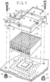
- the heat sink assembly of the invention comprises a thin spring steel bar 1, a frame preferably in plastic material, a dissipating element, in high thermal conductivity material, preferably aluminium section and fastening means comprising two screws 4,5.
- the spring steel bar 1, of round section, is shaped by cold bending so a to form a double angle element comprising a central portion 1, operative as torsion bar, ending in two arms 7,8 respectively, perpendicular to the central portion 1 and parallel each to the other, operative as torsion bar loading arms.
- the free end of the arms is inwardly right angle bent in the extending direction of the torsion bar 1 to form two hooking elements 9,10 respectively.
- the torsion bar may have a section with diameter in the order of 1,3 mm and a lenght in the order of 48 mm, the lenght of the arms 7,8, equal to each other, being in the order of 20 mm.
- the frame 2 preferably square and obtained by plastic molding, comprises four side elements forming a square section hollow prismatic body.
- Two opposite apexes of the frame 2 are provided with cylindrical eylets 11,12, having axis parallel to the one of the primatic body, the eylets 11,12 receiving screws 4 and 5.
- the lower face of the prismatic body forms a bearing surface of the frame 2 against a printed circuit board.
- Two opposite side plates 13,14 of the frame 2 have, at their median section, on the frame upper face 15, opposite and parallel to the lower face, two saddles 16,17 receiving and positioning the torsion bar 1.
- the opposite side plates 13,14 each have, at the end proximate to eylets 11,12 respectively, an elongated latching recess for housing one of the hooking elements 9,10.
- the recess and hooking element pair forms a composite slide-hinge constraint preventing any traverse of the hooking element from the plane of the printed circuit board.
- Similar positioning saddles 27,18 and similar housing recesses are provided in the other pair of opposite side plates 30,31 allowing the installation of the torsion bar on the frame, in one or the other of two positions, orthogonal each other, at choice.
- the preloaded torsion state is obtained independently of and without intervention of other elements, such as the die or the printed circuit board.
- the frame sides may have a lenght in the order of 45 mm and form a square section prismatic housing having side width in the order of 38 mm and height in the order of 7 mm.
- the heat sink 3 is inserted in this housing from the lower face of the frame.
- the heat sink 9 is formed in conventional way from a plate having a plurality of radiating fins 19 perpendicular to the plate and parallel each to the other.
- the torsion bar 1 When the heat sink is fully inserted in the housing the torsion bar 1 is inserted in a groove formed by two adjacent fins 19A,19B in the median section of the heat sink.
- the heat sink size corresponds to the one of the housing formed by the frame.
- the heat sink 3 may have a square base plate with side lenght in the order of 38 mm, thickness in the order of 5 mm and radiating fin height in the order of 15-20 mm.
- the set so assembled, as shown in figure 2, with screws 4 and 5 inserted in the corresponding eylets 11,12 may be laid down on an integrated circuit die mounted on a printed circuit board and may be secured to the board by screws 4,5
- Figure 1 shows a die 19 having a size in the order of 10x10x0,8 mm mounted on a intermediate ceramic support 20 for instance by soldering technique known as flip-chip bonding.
- the intermediate ceramic support 20 having size in the order of 20x20x1 mm may be bonded to a printed circuit board 21 by the same technique.
- Board 21 is provided with threaded inserts 22,23 fixed to the board with the technique known as "press-fit".
- the inserts have a ledge 24,25.
- the screws 4 and 5 are screwed in the inserts 22,23 and provide the fastening of the heat sink assembly to the board 21, as shown in figure 3.
- Heat sink and frame overlap a printed circuit board area whose boundary is identified in figure 1 by the dotted line square 26.
- test pads 27 may be present, easily accessible by removal of the heat sink assembly.
- the frame 2 height is suitably selected so as to be about 1 mm less than the sum of
- the torsion bar 1 interferes with the dissipation plate 3 urging it against the die and at the same time resiliently yielding, owing to a slight rotation of the arm 7,8 which gradually increases the preloaded torsional state of the bar, up to a predetermined value.
- the dissipator may adjust its position in perfect contact of the die surface and take the required incidence without modification of the load conditions and without development of undesired non uniform pressure distribution on the die.
- torsion bar 1 is shown in section view according to a plane perpendicular to its lenght.
- Arrow F1 is the force applied by the hooking constraint to the arm 7 end.
- Arrow F2 is the force applied by the hooking contstraint to the arm 8 end.
- Arrow F3 is the reaction force exerted on bar 1 by the die 19, through the dissipation plate 3.
- the torsional state of the bar essentially depends on the distance of bar 1 from the constrain plane formed by the frame lower surface, hence on the preload state imposed by the frame height and on the interference between dissipator 3 and die 19 which is not modified in substantive way by size allowances.
- arms 7,8 are subjected to virtual rotations having the same amplitude and opposite direction so that the twisting torque developed by the bar is not changed and necessarily the load state is unchanged too.
- the dissipator plate adjusts uniformly in contact with the die upper surface, irrespective of the possible incidence of the die upper surface relative to the board, with a predetermined urging force F3 which assures a controlled and uniform contact pressure.
- the thermal exchange between die and plate is then provided by the tight contact and, if required, by interposing a film of silicon grease between the two elements.
- a further advantage provided by the heat sink assembly is that being the preloaded state of the torsion bar caused by the interaction of the bar with the frame, when the heat sink assembly is brought in contact with the die and laid down on it without effort, the frame is spaced apart from the printed circuit of about one millimeter only.
- clamping screws 4,5 having a lenght sligtly greater than the sum of the board thickness and the depth of eylets 11,12 for properly mounting the assembly on the board.
- Screws 4 and 5 can be screwed in the inserts 22,23 nearly entirely and once clamping is completed they extend beyond the board of about one millimeter only,thus avoiding possible interference with electronic components mounted on a second printed circuit board adjacent and parallel to the first one.
- the mounting operation of the assembly can be performed withoud effort and without acting on the torsion arm with the certainly that no undesired stresses are applied to the die.
- the bar still remains in preloaded state and there is no risk of disenganging it from the frame.
- a further advantage offered by the heat sink assembly shown in the figures is that by providing two pair of recesses, such as 18, symmetrically located relative to the diagonal defined by eylets 11,12, the torsion bar 1 may be positioned relative to the frame in either one or the other of two positions rotated 90° the one as to the other to allows the installation of the heat sink 3 in the frame 2 in either one or the other of two positions.
- the orientation of the heat sink radiating fins may be chosen between two directions to provide the maximum dissipation effect in presence of ventilation flows having a predetermined direction.
- the frame may have a rectangular shape, not a square one, and the heat sink, obtained by die casting may be provided with non parallel radiating fins, provided they offer a rectilinear median housing to the torsion bar.
- eylets rather than two, may be provided and the screw 4, insert 22 pair may be substituted by screws passing in the printed circuit board (possibly by studs too) to which the assembly is fixed by nuts.
- the coupling between heat sink 3 and frame 2 may be rendered unloosable by providing hooking elements 9,10 suitably long such as to cause interference with the heat sink 3.
- the frame side may have openings to allow for a ventilation flow lapping the lower surface of plate 3 contacting the die.
- the frame may be substituted by centering and preloading means as shown in figure 6.
- two plastic elements 34,35 form each a shim having a face 36,37 respectively, resting against the lower surface of the heat sink 3, and two corner reliefs 38,39 and 40,41 respectively, which provide the positioning of the elements against two corner edges 42,43 of the heat sink.
- the two elements are urged against the heat sink, by the action of the torsion bar 1, whose hooking elements are engaged in recesses similar to recess 18 of figure 1 provided in the lower surface of the shims.
- the torsional bar 1 preloading is provided by the cooperation of heat sink 3 with elements 34,35.
- the heat sink size it is possible to provide in the heat sink plate 3, at corner positions thereof, a pair of cylindrical seats 44,45 where two plastic guiding bushings 46,47 are inserted.
- the bushings have a stop collar 48,49 acting as preloading shim and provided with a recess for housing the hooking elements 9 or 10 of the torsion bar.
- the bushing 46,47 are retained in the heat sink seats by the twisting moment exerted by the bar 1.
- heat sink assembly of the present invention is expressely aimed at use with naked integrated circuits, its utility is not limited to the combination with such circuits, and the assembly can be advantageously used with any kind of integrated circuit, even packaged, where a thermally conductive package surface, plane and parallel to the supporting printed circuit board is present.
Landscapes
- Cooling Or The Like Of Electrical Apparatus (AREA)
- Cooling Or The Like Of Semiconductors Or Solid State Devices (AREA)
Priority Applications (1)
| Application Number | Priority Date | Filing Date | Title |
|---|---|---|---|
| EP93830463A EP0654822A1 (fr) | 1993-11-19 | 1993-11-19 | Assemblage de refroidissement pour dispositif de circuit intégré |
Applications Claiming Priority (1)
| Application Number | Priority Date | Filing Date | Title |
|---|---|---|---|
| EP93830463A EP0654822A1 (fr) | 1993-11-19 | 1993-11-19 | Assemblage de refroidissement pour dispositif de circuit intégré |
Publications (1)
| Publication Number | Publication Date |
|---|---|
| EP0654822A1 true EP0654822A1 (fr) | 1995-05-24 |
Family
ID=8215250
Family Applications (1)
| Application Number | Title | Priority Date | Filing Date |
|---|---|---|---|
| EP93830463A Ceased EP0654822A1 (fr) | 1993-11-19 | 1993-11-19 | Assemblage de refroidissement pour dispositif de circuit intégré |
Country Status (1)
| Country | Link |
|---|---|
| EP (1) | EP0654822A1 (fr) |
Cited By (4)
| Publication number | Priority date | Publication date | Assignee | Title |
|---|---|---|---|---|
| EP0720224A1 (fr) * | 1994-12-29 | 1996-07-03 | Bull S.A. | Procédé et dispositif de fixation de deux éléments tels qu'un radiateur de circuit intégré à une carte de circuits imprimés |
| EP1290928A4 (fr) * | 2001-03-03 | 2004-07-28 | Zalman Tech Co Ltd | Dissipateur thermique et dispositif a dissipateur thermique comportant ledit dissipateur thermique |
| EP1414065A3 (fr) * | 2002-10-22 | 2006-05-24 | Siemens Aktiengesellschaft | Configuration de dispositifs à haute prestation pour l'intégration méchatronique de dispositifs à haute prestation |
| US7113406B1 (en) * | 2004-07-22 | 2006-09-26 | Cisco Technology, Inc. | Methods and apparatus for fastening a set of heatsinks to a circuit board |
Citations (3)
| Publication number | Priority date | Publication date | Assignee | Title |
|---|---|---|---|---|
| US3757271A (en) * | 1971-10-04 | 1973-09-04 | Ibm | Integrated circuit package |
| US4679118A (en) * | 1984-08-07 | 1987-07-07 | Aavid Engineering, Inc. | Electronic chip-carrier heat sinks |
| US5019940A (en) * | 1987-02-24 | 1991-05-28 | Thermalloy Incorporated | Mounting apparatus for electronic device packages |
-
1993
- 1993-11-19 EP EP93830463A patent/EP0654822A1/fr not_active Ceased
Patent Citations (3)
| Publication number | Priority date | Publication date | Assignee | Title |
|---|---|---|---|---|
| US3757271A (en) * | 1971-10-04 | 1973-09-04 | Ibm | Integrated circuit package |
| US4679118A (en) * | 1984-08-07 | 1987-07-07 | Aavid Engineering, Inc. | Electronic chip-carrier heat sinks |
| US5019940A (en) * | 1987-02-24 | 1991-05-28 | Thermalloy Incorporated | Mounting apparatus for electronic device packages |
Non-Patent Citations (1)
| Title |
|---|
| "Cooling Enhancement of Intel 386/486 by Clip-on Heat Sink", IBM TECHNICAL DISCLOSURE BULLETIN., vol. 33, no. 2, July 1990 (1990-07-01), NEW YORK US, pages 218 - 219 * |
Cited By (4)
| Publication number | Priority date | Publication date | Assignee | Title |
|---|---|---|---|---|
| EP0720224A1 (fr) * | 1994-12-29 | 1996-07-03 | Bull S.A. | Procédé et dispositif de fixation de deux éléments tels qu'un radiateur de circuit intégré à une carte de circuits imprimés |
| EP1290928A4 (fr) * | 2001-03-03 | 2004-07-28 | Zalman Tech Co Ltd | Dissipateur thermique et dispositif a dissipateur thermique comportant ledit dissipateur thermique |
| EP1414065A3 (fr) * | 2002-10-22 | 2006-05-24 | Siemens Aktiengesellschaft | Configuration de dispositifs à haute prestation pour l'intégration méchatronique de dispositifs à haute prestation |
| US7113406B1 (en) * | 2004-07-22 | 2006-09-26 | Cisco Technology, Inc. | Methods and apparatus for fastening a set of heatsinks to a circuit board |
Similar Documents
| Publication | Publication Date | Title |
|---|---|---|
| US5109317A (en) | Mounting mechanism for mounting heat sink on multi-chip module | |
| US5089936A (en) | Semiconductor module | |
| JP3810458B2 (ja) | ヒートシンクアッセンブリー及びその製造方法 | |
| JP3560649B2 (ja) | ヒートシンクと装着部材の組合せ | |
| US7375963B2 (en) | System and method for cooling a module | |
| US5276585A (en) | Heat sink mounting apparatus | |
| US6046498A (en) | Device having a heat sink for cooling an integrated circuit | |
| US4974119A (en) | Conforming heat sink assembly | |
| JP3426368B2 (ja) | ヒートシンクの留め具 | |
| US5373099A (en) | Fixing device for fixing electronic component against a wall of a heatsink | |
| CA2139266C (fr) | Boitier de dispositif a semiconducteur | |
| EP1401017A2 (fr) | Boítier pour montage sur une carte imprimée | |
| JP4022528B2 (ja) | 直動スライドカムを保持した板ばね荷重プレート | |
| CZ108093A3 (en) | Assembly system of a heat collector for a semiconductor device and assembly process thereof | |
| HK34396A (en) | Self-adjusting heat sink design for vlsi packages | |
| JP6432676B2 (ja) | マルチチップ自己調整式冷却ソリューション | |
| US6788538B1 (en) | Retention of heat sinks on electronic packages | |
| JPH0581185B2 (fr) | ||
| JP2008502138A (ja) | 半導体冷却装置の連結装置及び取付方法 | |
| JP2008502138A5 (fr) | ||
| CN217740516U (zh) | 散热器、散热单元及服务器 | |
| US10366939B2 (en) | Heat sink fastening system and method | |
| JPH0573269B2 (fr) | ||
| EP0654822A1 (fr) | Assemblage de refroidissement pour dispositif de circuit intégré | |
| JP2766068B2 (ja) | 電子装置におけるヒートシンクの取り外し方法 |
Legal Events
| Date | Code | Title | Description |
|---|---|---|---|
| PUAI | Public reference made under article 153(3) epc to a published international application that has entered the european phase |
Free format text: ORIGINAL CODE: 0009012 |
|
| AK | Designated contracting states |
Kind code of ref document: A1 Designated state(s): DE FR GB IT |
|
| 17P | Request for examination filed |
Effective date: 19950630 |
|
| 17Q | First examination report despatched |
Effective date: 19970509 |
|
| RAP1 | Party data changed (applicant data changed or rights of an application transferred) |
Owner name: BULL S.A. |
|
| GRAG | Despatch of communication of intention to grant |
Free format text: ORIGINAL CODE: EPIDOS AGRA |
|
| STAA | Information on the status of an ep patent application or granted ep patent |
Free format text: STATUS: THE APPLICATION HAS BEEN REFUSED |
|
| 18R | Application refused |
Effective date: 20020120 |