EP0654845A1 - Anpassbares Dipolstrahlerelement in gedruckter Schaltungstechnik, Verfahren zur Einstellung der Anpassung und entsprechende Gruppenantenne - Google Patents
Anpassbares Dipolstrahlerelement in gedruckter Schaltungstechnik, Verfahren zur Einstellung der Anpassung und entsprechende Gruppenantenne Download PDFInfo
- Publication number
- EP0654845A1 EP0654845A1 EP94460042A EP94460042A EP0654845A1 EP 0654845 A1 EP0654845 A1 EP 0654845A1 EP 94460042 A EP94460042 A EP 94460042A EP 94460042 A EP94460042 A EP 94460042A EP 0654845 A1 EP0654845 A1 EP 0654845A1
- Authority
- EP
- European Patent Office
- Prior art keywords
- radiating element
- end portion
- slot
- variable
- supply line
- Prior art date
- Legal status (The legal status is an assumption and is not a legal conclusion. Google has not performed a legal analysis and makes no representation as to the accuracy of the status listed.)
- Granted
Links
- 230000006978 adaptation Effects 0.000 title claims description 24
- 238000000034 method Methods 0.000 title claims description 7
- 238000005516 engineering process Methods 0.000 title description 5
- 239000000758 substrate Substances 0.000 claims abstract description 16
- 230000008878 coupling Effects 0.000 claims abstract description 12
- 238000010168 coupling process Methods 0.000 claims abstract description 12
- 238000005859 coupling reaction Methods 0.000 claims abstract description 12
- 239000002184 metal Substances 0.000 claims description 6
- 230000005855 radiation Effects 0.000 claims description 6
- 239000004020 conductor Substances 0.000 claims description 3
- 230000001186 cumulative effect Effects 0.000 claims description 2
- 238000001465 metallisation Methods 0.000 abstract 1
- 238000010586 diagram Methods 0.000 description 3
- 239000004809 Teflon Substances 0.000 description 2
- 229920006362 Teflon® Polymers 0.000 description 2
- 230000000694 effects Effects 0.000 description 2
- 238000005259 measurement Methods 0.000 description 2
- 230000004048 modification Effects 0.000 description 2
- 238000012986 modification Methods 0.000 description 2
- 230000003247 decreasing effect Effects 0.000 description 1
- 239000006185 dispersion Substances 0.000 description 1
- 235000021183 entrée Nutrition 0.000 description 1
- 230000005284 excitation Effects 0.000 description 1
- 238000012423 maintenance Methods 0.000 description 1
- 230000006855 networking Effects 0.000 description 1
- 230000008569 process Effects 0.000 description 1
- 230000009467 reduction Effects 0.000 description 1
- 230000007704 transition Effects 0.000 description 1
- 238000003466 welding Methods 0.000 description 1
Images


Classifications
-
- H—ELECTRICITY
- H01—ELECTRIC ELEMENTS
- H01Q—ANTENNAS, i.e. RADIO AERIALS
- H01Q9/00—Electrically-short antennas having dimensions not more than twice the operating wavelength and consisting of conductive active radiating elements
- H01Q9/04—Resonant antennas
- H01Q9/06—Details
- H01Q9/065—Microstrip dipole antennas
-
- H—ELECTRICITY
- H01—ELECTRIC ELEMENTS
- H01Q—ANTENNAS, i.e. RADIO AERIALS
- H01Q21/00—Antenna arrays or systems
- H01Q21/06—Arrays of individually energised antenna units similarly polarised and spaced apart
- H01Q21/061—Two dimensional planar arrays
- H01Q21/062—Two dimensional planar arrays using dipole aerials
-
- H—ELECTRICITY
- H01—ELECTRIC ELEMENTS
- H01Q—ANTENNAS, i.e. RADIO AERIALS
- H01Q9/00—Electrically-short antennas having dimensions not more than twice the operating wavelength and consisting of conductive active radiating elements
- H01Q9/04—Resonant antennas
- H01Q9/16—Resonant antennas with feed intermediate between the extremities of the antenna, e.g. centre-fed dipole
- H01Q9/28—Conical, cylindrical, cage, strip, gauze, or like elements having an extended radiating surface; Elements comprising two conical surfaces having collinear axes and adjacent apices and fed by two-conductor transmission lines
- H01Q9/285—Planar dipole
Definitions
- the field of the invention is that of telecommunications antennas up to frequencies of the order of a gigahertz.
- the invention relates to a radiating element of the dipole type. Indeed, it is still common in high frequency telecommunications to use such a radiating element of the dipole type as an omnidirectional transmitting or receiving antenna.
- the invention has numerous applications, such as, for example, field readings, of the type of antenna diagram measurement or even measurement of electromagnetic compatibility.
- the radiating elements of the dipole type known from the prior art generally consist of elements of two-wire lines, that is to say of conductive cylindrical rods, supplied by a supply line.
- the supply lines (for example the coaxial lines) are generally asymmetrical, while the radiating elements are themselves symmetrical.
- balun in order for the radiation from these radiating elements to be acceptable, a balun should be used.
- a balun is traditionally represented as a transformer which involves localized or distributed impedances, and allows, when placed between a symmetrical radiating element and an asymmetrical supply line, to make the currents symmetrical on the radiating structure.
- Such a balun has the major drawback of requiring always delicate focusing.
- Radiating elements are also known which consist of cylindrical rods which are self-symmetrized, so that they can be used without a balun. Obtaining such an autosymmetry characteristic on these radiating elements cannot however be obtained only at the expense of an increased complexity of their structure.
- the energy emitted by a generator and transmitted to a radiating element by a supply line is not radiated by the radiating element but returned to the generator.
- this adaptation is achieved through the use of two additional sections (or stubs) placed one in series and the other in parallel.
- stubs additional sections
- the determination of the length of each stub (series or parallel) being empirical, the adaptation requires numerous welding / unsoldering operations.
- the invention particularly aims to overcome these various drawbacks of the state of the art.
- an objective of the invention is to provide a radiating element of the dipole type which has a large passband and omnidirectional patterns while having a small footprint and a very simple mechanical implementation.
- the invention also aims to provide such a radiating element of the dipole type which does not require the joint use of a balun.
- Another object of the invention is to provide such a radiating element of the dipole type which is easily adaptable to the supply line to which it is connected.
- the radiating element according to the invention is therefore produced in printed technology, which allows a considerable saving of space and a much easier mechanical maintenance.
- the metal deposit comprises on the one hand the two lateral strands (forming the horizontal bar of the T) which constitute the dipole proper, and on the other hand an extension, in a direction orthogonal to these lateral strands (extension forming the vertical bar of T), which constitutes the ground plane for the supply line.
- the radiating element according to the invention does not require the joint use of a balun.
- the supply line feeds the two side strands via the coupling slot.
- the radiating element according to the invention is also adaptable thanks to the first and / or second means with variable capacity.
- the modification of the capacity of the first means has the same effect as an elongation or a "physical" (that is to say real) reduction in the first variable length.
- said slot is of rectangular shape.
- the cumulative length of all of said two lateral strands is substantially equal to half the operating wavelength of said radiating element.
- said two lateral strands are of the same length.
- said supply line is a microstrip line.
- the radiating element also comprises reflection means making it possible to suppress rear radiation from said radiating element.
- the energy radiated by the radiating element is directed forward. This allows to gain approximately 3 dB on the maximum directivity of the radiating element.
- the invention also relates to a network of radiating elements comprising at least at least two radiating elements according to the invention.
- the invention also relates to a method of adjusting the adaptation of a radiating element, characterized in that it comprises a first step of adjusting said first variable length and a second step of adjusting said second variable length.
- said first step of adjusting the first variable length consists in modifying the value of the capacity of first means with variable capacity connected between a ground plane and the end of the line feed located in the first end portion
- said second step of adjusting the second variable length consists in modifying the value of the capacity of second variable capacity means connected between a ground plane and the end of the slot located in the second end portion
- said first step of adjusting the first variable length also consists in partially cutting said first end portion of the supply line, and said second step of adjusting the second variable length also includes partially plugging said second end portion of the slot with a conductive material.
- the invention therefore relates to a radiating element of the dipole type produced in printed technology.
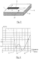
- Figure 1 shows a perspective view of an embodiment of such a radiating element.
- the radiating element according to the invention mainly comprises a substrate plate 1, a supply line 2, and a metallic deposit 3.
- the supply line 2 is located on the underside of the substrate plate 1. It is, for example, a microstrip line of width w. This supply line 2 is connected to a connector 4 (for example of the SMA type) making it possible to connect the radiating element to a traditional coaxial cable (not shown).
- a connector 4 for example of the SMA type
- the metal deposit 3 is located on the upper face of the substrate plate 1 and is T-shaped.
- the horizontal bar of this T of the metallic deposit which is the radiating part 8 of the radiating element, consists of two lateral strands 5,6 separated by a coupling slot 7.
- the length L and the width W of this radiating part 8 determine the mechanical properties specific to the radiating element.
- the two lateral strands 5,6 have the same length L / 2.
- the supply line 2 supplies the radiating part 8 (that is to say the two lateral strands 5, 6) via the coupling slot 7.
- This slot 7 is for example of rectangular shape.
- the vertical bar 11 of the T of the metal deposit 3 extends from the two lateral strands 5, 6 to the connector 4.
- This part 11 of the metal deposit 3 constitutes a ground plane for the supply line 2 situated on the other face of the substrate plate 1.
- the radiating element generates symmetrical currents on the radiating part 8.
- the radiating element of the invention is self-symmetrized.
- the supply line 2 has at its end opposite to that connected to the connector 4, an end portion of length l1 extending beyond the axis of the slot 7. This first length l1 of the end portion of the supply line 2 constitutes a series 9 open-circuit stub.
- the coupling slot 7 has an end portion of length l2 extending beyond the supply line 2. This second length l2 of the end portion of the slot 7 constitutes a parallel stub 10 short-circuited slotted line.
- the radiating element according to the invention comprises, although produced in a printed technologist, a series stub and a parallel stub. These two series and parallel stubs allow the adaptation of the radiating element, according to the principle of double stub adaptation, over a wide frequency band.
- FIG. 2 presents an equivalent electrical diagram of a radiating element according to the invention
- FIG. 5 presents a Smith abacus on which the main ones appear. stages of implementation of this principle.
- FIG. 4 shows a variation curve, as a function of frequency, of the standing wave ratio (ROS) for an example of a radiating element as shown in FIG. 1.
- ROS standing wave ratio
- This curve makes it possible to calculate the passband [f1, f2] of the radiating element, that is to say the frequency band for which the ROS is less than 2.
- This passband can also be expressed as a percentage, obtained by dividing the width (f2-f1) of the passband by the center frequency f3 of this passband.
- the radiating element according to the invention therefore has a wide pass band.
- FIG. 8 presents a variation curve, in a Smith chart, of the input impedance Z e for the previous example of a radiating element.
- variable capacity means are for example, as shown in Figure 3, varactors 31 controlled electronically.
- varying the capacity of these variable capacity means 31 has the same effect as lengthening or decreasing the length of the corresponding stub 9.
- such an adjustment of the adaptation of the radiating element consists in modifying the capacities of the first and / or second means with variable capacity, which is equivalent to a modification of the lengths 11, 12 of stubs.
- Figure 6 shows a second embodiment of a radiating element according to the invention.
- this second embodiment differs from the first only in that it comprises reflection means 61 making it possible to suppress rear radiation from this radiating element.
- the radiation of the dipole alone 62 is omnidirectional except in the axis of the dipole.
- it is desired to direct the radiated energy towards the front of the dipole that is to say on the side opposite to the excitation).
- reflection means 61 aim to increase the directivity of the assembly 62 produced in printed technology (and corresponding to the radiating element of the first embodiment).
- reflection means 61 in the case where they consist of a reflector (in the absence of an ideally undefined defector plane), make it possible to gain approximately 3 dB on the maximum directivity.
- the reflector 61 can have many other shapes than that presented in FIG. 6.
- FIG. 7 shows an example of an array 71 of radiating elements 72 according to the invention.
- the networking of radiating elements also makes it possible to obtain increased directivity and can therefore be combined or not with a reflector.
- the network 71 comprises three radiating elements 72 as well as a reflector 73.
Landscapes
- Variable-Direction Aerials And Aerial Arrays (AREA)
Applications Claiming Priority (2)
| Application Number | Priority Date | Filing Date | Title |
|---|---|---|---|
| FR9314276 | 1993-11-24 | ||
| FR9314276A FR2713020B1 (fr) | 1993-11-24 | 1993-11-24 | Elément rayonnant du type dipôle réalisé en technologie imprimée, procédé d'ajustement de l'adaptation et réseau correspondants. |
Publications (2)
| Publication Number | Publication Date |
|---|---|
| EP0654845A1 true EP0654845A1 (de) | 1995-05-24 |
| EP0654845B1 EP0654845B1 (de) | 1999-01-20 |
Family
ID=9453343
Family Applications (1)
| Application Number | Title | Priority Date | Filing Date |
|---|---|---|---|
| EP19940460042 Expired - Lifetime EP0654845B1 (de) | 1993-11-24 | 1994-11-18 | Anpassbares Dipolstrahlerelement in gedruckter Schaltungstechnik, Verfahren zur Einstellung der Anpassung und entsprechende Gruppenantenne |
Country Status (3)
| Country | Link |
|---|---|
| EP (1) | EP0654845B1 (de) |
| DE (1) | DE69416088T2 (de) |
| FR (1) | FR2713020B1 (de) |
Cited By (1)
| Publication number | Priority date | Publication date | Assignee | Title |
|---|---|---|---|---|
| EP1073143A1 (de) * | 1999-07-30 | 2001-01-31 | France Telecom | Dualpolarisierte gedruckte Antenne und entsprechende Gruppenantenne |
Families Citing this family (3)
| Publication number | Priority date | Publication date | Assignee | Title |
|---|---|---|---|---|
| FR2854739A1 (fr) * | 2003-05-06 | 2004-11-12 | France Telecom | Dispositif formant antenne, capteur ou sonde electromagnetique |
| FR2882468A1 (fr) | 2005-02-18 | 2006-08-25 | France Telecom | Antenne dipole imprimee multibandes |
| US8203499B2 (en) * | 2008-05-19 | 2012-06-19 | Galtronics Corporation Ltd. | Conformable antenna |
Citations (3)
| Publication number | Priority date | Publication date | Assignee | Title |
|---|---|---|---|---|
| US3845490A (en) * | 1973-05-03 | 1974-10-29 | Gen Electric | Stripline slotted balun dipole antenna |
| US4114163A (en) * | 1976-12-06 | 1978-09-12 | The United States Of America As Represented By The Secretary Of The Army | L-band radar antenna array |
| US4825220A (en) * | 1986-11-26 | 1989-04-25 | General Electric Company | Microstrip fed printed dipole with an integral balun |
-
1993
- 1993-11-24 FR FR9314276A patent/FR2713020B1/fr not_active Expired - Fee Related
-
1994
- 1994-11-18 EP EP19940460042 patent/EP0654845B1/de not_active Expired - Lifetime
- 1994-11-18 DE DE1994616088 patent/DE69416088T2/de not_active Expired - Fee Related
Patent Citations (3)
| Publication number | Priority date | Publication date | Assignee | Title |
|---|---|---|---|---|
| US3845490A (en) * | 1973-05-03 | 1974-10-29 | Gen Electric | Stripline slotted balun dipole antenna |
| US4114163A (en) * | 1976-12-06 | 1978-09-12 | The United States Of America As Represented By The Secretary Of The Army | L-band radar antenna array |
| US4825220A (en) * | 1986-11-26 | 1989-04-25 | General Electric Company | Microstrip fed printed dipole with an integral balun |
Non-Patent Citations (1)
| Title |
|---|
| EDWARD AND REES: "A Broadband Printed Dipole with Integrated Balun", MICROWAVE JOURNAL., vol. 30, no. 5, DEDHAM US, pages 339 - 344 * |
Cited By (3)
| Publication number | Priority date | Publication date | Assignee | Title |
|---|---|---|---|---|
| EP1073143A1 (de) * | 1999-07-30 | 2001-01-31 | France Telecom | Dualpolarisierte gedruckte Antenne und entsprechende Gruppenantenne |
| FR2797098A1 (fr) * | 1999-07-30 | 2001-02-02 | France Telecom | Antenne imprimee bi-polarisation et reseau d'antennes correspondant |
| US6281849B1 (en) | 1999-07-30 | 2001-08-28 | France Telecom | Printed bi-polarization antenna and corresponding network of antennas |
Also Published As
| Publication number | Publication date |
|---|---|
| EP0654845B1 (de) | 1999-01-20 |
| FR2713020A1 (fr) | 1995-06-02 |
| FR2713020B1 (fr) | 1996-02-23 |
| DE69416088T2 (de) | 1999-09-16 |
| DE69416088D1 (de) | 1999-03-04 |
Similar Documents
| Publication | Publication Date | Title |
|---|---|---|
| CA1291560C (fr) | Antenne de type helice et son procede de realisation | |
| EP0888647B1 (de) | Wendelantenne mit integrierter breitbandspeisung und verfahren zu deren herstellung | |
| CA2148796C (fr) | Antenne fil-plaque monopolaire | |
| FR2727250A1 (fr) | Antenne large bande monopole en technologie imprimee uniplanaire et dispositif d'emission et/ou de reception incorporant une telle antenne | |
| FR2810163A1 (fr) | Perfectionnement aux antennes-sources d'emission/reception d'ondes electromagnetiques | |
| EP2710676B1 (de) | Strahlerelement für eine aktive gruppenantenne aus elementarfliesen | |
| FR2752646A1 (fr) | Antenne imprimee plane a elements superposes court-circuites | |
| EP0542595A1 (de) | Mikrostreifenleiterantenne, insbesondere für Fernsprechübertragungen von Satelliten | |
| FR2556510A1 (fr) | Antenne periodique plane | |
| EP0243289A1 (de) | Plattenantenne mit zwei gekreuzten Polarisationen | |
| FR2669776A1 (fr) | Antenne hyperfrequence a fente a structure de faible epaisseur. | |
| FR2645353A1 (fr) | Antenne plane | |
| FR2652453A1 (fr) | Antenne coaxiale a fentes du type a alimentation a ondes progressives. | |
| EP3235058B1 (de) | Drahtplattenantenne mit einem kapazitiven dach mit einem schlitz zwischen der speisungssonde und dem kurzschlussdraht | |
| FR2746548A1 (fr) | Antenne helicoidale a moyens de duplexage integres, et procedes de fabrication correspondants | |
| EP3180816A1 (de) | Mehrbandige quelle mit koaxialem horn mit monopulsnachführungsverfahren für eine reflektorantenne | |
| EP0654845B1 (de) | Anpassbares Dipolstrahlerelement in gedruckter Schaltungstechnik, Verfahren zur Einstellung der Anpassung und entsprechende Gruppenantenne | |
| EP0605338A1 (de) | Streifenleitungsantenne mit zwei Polarisationen und entsprechende Vorrichtung zum Senden/Empfangen | |
| FR2844923A1 (fr) | Antenne helicoidale a large bande | |
| FR2610765A1 (fr) | Filtre hyperfrequence accordable | |
| EP0477102B1 (de) | Richtnetzwerk mit benachbarten Strahlerelementen für Funkübertragungssystem und Einheit mit einem derartigen Richtnetzwerk | |
| WO1993000718A1 (fr) | Dispositif de filtrage coupe-bande hyperfrequence accordable | |
| EP0991135B1 (de) | Selektive Antenne mit Frequenzumschaltung | |
| EP3155690A1 (de) | Flachantenne zur satellitenkommunikation | |
| FR2705167A1 (fr) | Antenne plaquée large bande à encombrement réduit, et dispositif d'émission/réception correspondant. |
Legal Events
| Date | Code | Title | Description |
|---|---|---|---|
| PUAI | Public reference made under article 153(3) epc to a published international application that has entered the european phase |
Free format text: ORIGINAL CODE: 0009012 |
|
| AK | Designated contracting states |
Kind code of ref document: A1 Designated state(s): DE GB |
|
| 17P | Request for examination filed |
Effective date: 19950830 |
|
| GRAG | Despatch of communication of intention to grant |
Free format text: ORIGINAL CODE: EPIDOS AGRA |
|
| 17Q | First examination report despatched |
Effective date: 19980122 |
|
| GRAG | Despatch of communication of intention to grant |
Free format text: ORIGINAL CODE: EPIDOS AGRA |
|
| GRAH | Despatch of communication of intention to grant a patent |
Free format text: ORIGINAL CODE: EPIDOS IGRA |
|
| GRAH | Despatch of communication of intention to grant a patent |
Free format text: ORIGINAL CODE: EPIDOS IGRA |
|
| GRAA | (expected) grant |
Free format text: ORIGINAL CODE: 0009210 |
|
| AK | Designated contracting states |
Kind code of ref document: B1 Designated state(s): DE GB |
|
| REF | Corresponds to: |
Ref document number: 69416088 Country of ref document: DE Date of ref document: 19990304 |
|
| PG25 | Lapsed in a contracting state [announced via postgrant information from national office to epo] |
Ref country code: DE Free format text: LAPSE BECAUSE OF FAILURE TO SUBMIT A TRANSLATION OF THE DESCRIPTION OR TO PAY THE FEE WITHIN THE PRESCRIBED TIME-LIMIT Effective date: 19990421 |
|
| GBT | Gb: translation of ep patent filed (gb section 77(6)(a)/1977) |
Effective date: 19990416 |
|
| PLBE | No opposition filed within time limit |
Free format text: ORIGINAL CODE: 0009261 |
|
| STAA | Information on the status of an ep patent application or granted ep patent |
Free format text: STATUS: NO OPPOSITION FILED WITHIN TIME LIMIT |
|
| 26N | No opposition filed | ||
| REG | Reference to a national code |
Ref country code: GB Ref legal event code: IF02 |
|
| PGFP | Annual fee paid to national office [announced via postgrant information from national office to epo] |
Ref country code: GB Payment date: 20061026 Year of fee payment: 13 |
|
| PGFP | Annual fee paid to national office [announced via postgrant information from national office to epo] |
Ref country code: DE Payment date: 20061108 Year of fee payment: 13 |
|
| GBPC | Gb: european patent ceased through non-payment of renewal fee |
Effective date: 20071118 |
|
| PG25 | Lapsed in a contracting state [announced via postgrant information from national office to epo] |
Ref country code: DE Free format text: LAPSE BECAUSE OF NON-PAYMENT OF DUE FEES Effective date: 20080603 |
|
| PG25 | Lapsed in a contracting state [announced via postgrant information from national office to epo] |
Ref country code: GB Free format text: LAPSE BECAUSE OF NON-PAYMENT OF DUE FEES Effective date: 20071118 |