EP0654865A1 - Elektrischer Steckverbinder mit Überbrückungen - Google Patents
Elektrischer Steckverbinder mit Überbrückungen Download PDFInfo
- Publication number
- EP0654865A1 EP0654865A1 EP93117373A EP93117373A EP0654865A1 EP 0654865 A1 EP0654865 A1 EP 0654865A1 EP 93117373 A EP93117373 A EP 93117373A EP 93117373 A EP93117373 A EP 93117373A EP 0654865 A1 EP0654865 A1 EP 0654865A1
- Authority
- EP
- European Patent Office
- Prior art keywords
- shunt
- electrical component
- connector
- modular jack
- passive electrical
- Prior art date
- Legal status (The legal status is an assumption and is not a legal conclusion. Google has not performed a legal analysis and makes no representation as to the accuracy of the status listed.)
- Granted
Links
- 239000007769 metal material Substances 0.000 claims description 5
- 229910000679 solder Inorganic materials 0.000 description 5
- 230000013011 mating Effects 0.000 description 4
- 230000000295 complement effect Effects 0.000 description 3
- 239000003292 glue Substances 0.000 description 2
- 235000014676 Phragmites communis Nutrition 0.000 description 1
- 239000003990 capacitor Substances 0.000 description 1
- 239000003989 dielectric material Substances 0.000 description 1
- 230000037431 insertion Effects 0.000 description 1
- 238000003780 insertion Methods 0.000 description 1
- 238000005476 soldering Methods 0.000 description 1
Images
Classifications
-
- H—ELECTRICITY
- H01—ELECTRIC ELEMENTS
- H01R—ELECTRICALLY-CONDUCTIVE CONNECTIONS; STRUCTURAL ASSOCIATIONS OF A PLURALITY OF MUTUALLY-INSULATED ELECTRICAL CONNECTING ELEMENTS; COUPLING DEVICES; CURRENT COLLECTORS
- H01R13/00—Details of coupling devices of the kinds covered by groups H01R12/70 or H01R24/00 - H01R33/00
- H01R13/66—Structural association with built-in electrical component
- H01R13/70—Structural association with built-in electrical component with built-in switch
- H01R13/703—Structural association with built-in electrical component with built-in switch operated by engagement or disengagement of coupling parts, e.g. dual-continuity coupling part
- H01R13/7031—Shorting, shunting or bussing of different terminals interrupted or effected on engagement of coupling part, e.g. for ESD protection, line continuity
- H01R13/7033—Shorting, shunting or bussing of different terminals interrupted or effected on engagement of coupling part, e.g. for ESD protection, line continuity making use of elastic extensions of the terminals
-
- H—ELECTRICITY
- H01—ELECTRIC ELEMENTS
- H01R—ELECTRICALLY-CONDUCTIVE CONNECTIONS; STRUCTURAL ASSOCIATIONS OF A PLURALITY OF MUTUALLY-INSULATED ELECTRICAL CONNECTING ELEMENTS; COUPLING DEVICES; CURRENT COLLECTORS
- H01R13/00—Details of coupling devices of the kinds covered by groups H01R12/70 or H01R24/00 - H01R33/00
- H01R13/66—Structural association with built-in electrical component
- H01R13/6608—Structural association with built-in electrical component with built-in single component
- H01R13/6616—Structural association with built-in electrical component with built-in single component with resistor
-
- H—ELECTRICITY
- H01—ELECTRIC ELEMENTS
- H01R—ELECTRICALLY-CONDUCTIVE CONNECTIONS; STRUCTURAL ASSOCIATIONS OF A PLURALITY OF MUTUALLY-INSULATED ELECTRICAL CONNECTING ELEMENTS; COUPLING DEVICES; CURRENT COLLECTORS
- H01R24/00—Two-part coupling devices, or either of their cooperating parts, characterised by their overall structure
- H01R24/60—Contacts spaced along planar side wall transverse to longitudinal axis of engagement
- H01R24/62—Sliding engagements with one side only, e.g. modular jack coupling devices
- H01R24/64—Sliding engagements with one side only, e.g. modular jack coupling devices for high frequency, e.g. RJ 45
Definitions
- This invention generally relates to the art of electrical connectors and, particularly, to a shunted electrical connector of the modular jack type and, still further, to such a connector incorporating a passive electrical component coupled in series with the shunt.
- a modular jack type connector which includes such components as shorting elements, bridging cards, shunting strips and the like to shunt or short selective different terminals of the connectors, particularly when the connectors are not receiving a mating connector plug.
- the shunting elements may be used to maintain line continuity when no plug is inserted into the jack.
- electrical connectors of the character described above include spring beam contacts which protrude from a portion of the jack housing into the receiving cavity of the jack.
- the contacts or terminals may be separated from each other by molded walls of the jack.
- the terminals include terminal portions, usually in the form of terminal pins, for mating with the terminals of a complementary electrical component.
- the terminal pins may form solder tails for insertion into holes in a printed circuit board.
- the terminal pins or solder tails are arranged in a single row, and in other instances the terminal pins or solder tails are arranged in two rows.
- This invention is directed to solving those problems by a simple concept of incorporating the passive electrical components directly on the shunting device, itself, either on or within the jack.
- An object, therefore, of the invention is to provide a new and improved shunted electrical connector, such as a modular jack type connector as described above, which incorporates a passive electrical component.
- the connector includes a dielectric housing defining a plug-receiving cavity open at one end of the housing.
- a plurality of terminals are mounted on the housing with contact portions extending within the cavity.
- a shunt bridges at least a pair of the terminals.
- the invention contemplates that a passive electrical component be coupled directly to the shunt on the connector.
- the shunt is provided as a two-part component, and the passive electrical component is coupled in series between the two parts.
- the two-part shunt is fabricated of sheet metal material, and the passive electrical component is soldered or glued using conductive glue to the two parts.
- the shunt is illustrated as a resistor to provide a load in the shunted circuit, and the shunt and the passive electrical component are mounted within the dielectric housing of the connector.
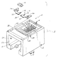
- a modular jack type electrical connector generally designated 10 which includes a dielectric housing, generally designated 12.
- the housing mounts a plurality of terminals, generally designated 14.
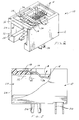
- a two-part shunt means generally designated 16 and seen best in Figure 1, is provided for shunting or shorting a pair of selective different terminals.
- the invention contemplates incorporating a passive electrical component 18 coupled directly to shunt means 16 on or within connector housing 12, as will be described in greater detail hereinafter.
- Housing 12 is a unitarily molded component of dielectric material, such as plastic or the like. As is known in the modular jack art, the housing defines a plug-receiving cavity, generally designated 20, which is open at a plug-receiving mouth 22 at one end 24 of the housing. The cavity is sized and shaped for receiving a complementary jack plug connector (not shown) which is inserted into cavity 20 from the open or mating end 24 of the housing. Housing 12 further includes one or more mounting pegs 26 for surface mounting the connector through appropriate holes in a printed circuit board, as is known in the art.
- Terminals 14 have spring contact portions 28 which are coplanar in a single row and which extend within cavity 20 for engaging appropriate contacts of the complementary mating jack plug connector.
- the terminals also have pins or solder tails 30 (Fig. 3) which are insertable through appropriate holes in a printed circuit board (not shown). Whereas spring contact portions 28 are coplanar in a single row, pins 30 are offset and alternate in two distinct rows. The pins form solder tails for soldering to appropriate circuit means on the board and/or in the holes. In an alternate embodiment surface mount type terminals may be used.
- Shunt means 16 is provided in the form of a two-part component comprised of two parts 32 which are spaced apart to define a gap 34 therebetween.
- the shunt parts are stamped and formed from sheet metal material and include holes 36 for mounting the shunt parts within a recessed area 38 of housing 12.
- the holes may receive integral plastic staking posts of the housing, or the holes may be alignable with holes 40 of the housing for receiving appropriate mounting or fastening means.
- Each shunt part 32 includes a contact finger 42 which is engageable with a spring contact portion 28 of a selected one of terminals 14 as shown in Figure 3 when no jack plug is inserted into cavity 20.
- the illustrated shunting scheme would be designed to maintain resistive line continuity when no plug is inserted into the jack.
- the invention contemplates incorporating passive electrical component 18 directly to shunt means 16 on or within connector housing 12. More particularly, as stated above, shunt parts 32 are separated by a gap 34 (Fig. 1) and this gap remains when shunt parts 32 are mounted within recessed area 38 of housing 12 as shown in Figure 2.
- other passive electrical components than a resistor are contemplated by the invention.
- the passive electrical component can be electrically coupled in series with the shunt means simply by spanning the gap between the two parts of the shunt means.
- the printed circuit board to which the modular jack is connected does not have to be customized to incorporate the passive electrical component therewithin.
Landscapes
- Details Of Connecting Devices For Male And Female Coupling (AREA)
Priority Applications (9)
| Application Number | Priority Date | Filing Date | Title |
|---|---|---|---|
| DE69320198T DE69320198T2 (de) | 1993-10-27 | 1993-10-27 | Elektrischer Steckverbinder mit Überbrückungen |
| EP93117373A EP0654865B1 (de) | 1993-10-27 | 1993-10-27 | Elektrischer Steckverbinder mit Überbrückungen |
| SG1996004038A SG43125A1 (en) | 1993-10-27 | 1993-10-27 | Shunted electrical connector |
| US08/313,473 US5542853A (en) | 1993-10-27 | 1994-09-27 | Shunted electrical connector |
| TW083108942A TW270245B (de) | 1993-10-27 | 1994-09-27 | |
| MYPI94002574A MY112783A (en) | 1993-10-27 | 1994-09-28 | Shunted electrical connector. |
| JP28442294A JP2934812B2 (ja) | 1993-10-27 | 1994-10-24 | シャント電気コネクタ |
| KR1019940027395A KR100191746B1 (ko) | 1993-10-27 | 1994-10-26 | 분류식 전기 커넥터 |
| HK98112466.3A HK1011467B (en) | 1998-11-30 | Shunted electrical connector |
Applications Claiming Priority (2)
| Application Number | Priority Date | Filing Date | Title |
|---|---|---|---|
| EP93117373A EP0654865B1 (de) | 1993-10-27 | 1993-10-27 | Elektrischer Steckverbinder mit Überbrückungen |
| SG1996004038A SG43125A1 (en) | 1993-10-27 | 1993-10-27 | Shunted electrical connector |
Publications (2)
| Publication Number | Publication Date |
|---|---|
| EP0654865A1 true EP0654865A1 (de) | 1995-05-24 |
| EP0654865B1 EP0654865B1 (de) | 1998-08-05 |
Family
ID=26133485
Family Applications (1)
| Application Number | Title | Priority Date | Filing Date |
|---|---|---|---|
| EP93117373A Expired - Lifetime EP0654865B1 (de) | 1993-10-27 | 1993-10-27 | Elektrischer Steckverbinder mit Überbrückungen |
Country Status (4)
| Country | Link |
|---|---|
| US (1) | US5542853A (de) |
| EP (1) | EP0654865B1 (de) |
| JP (1) | JP2934812B2 (de) |
| SG (1) | SG43125A1 (de) |
Cited By (9)
| Publication number | Priority date | Publication date | Assignee | Title |
|---|---|---|---|---|
| WO1999054968A1 (en) * | 1998-04-20 | 1999-10-28 | Pulse Engineering, Inc. | Modular microelectronic connector and method |
| WO2000022701A1 (en) * | 1998-10-09 | 2000-04-20 | Pulse Engineering, Inc. | Two-piece microelectronic connector and method |
| US6062908A (en) * | 1997-01-27 | 2000-05-16 | Pulse Engineering, Inc. | High density connector modules having integral filtering components within repairable, replaceable submodules |
| EP0969569A3 (de) * | 1998-06-05 | 2000-05-24 | Molex Incorporated | Ubersprechungsdämpfung für Steckverbinder |
| US6224425B1 (en) | 1998-04-20 | 2001-05-01 | Pulse Engineering, Inc. | Simplified microelectronic connector and method of manufacturing |
| US6325664B1 (en) | 1999-03-11 | 2001-12-04 | Pulse Engineering, Inc. | Shielded microelectronic connector with indicators and method of manufacturing |
| US6409548B1 (en) | 2000-11-02 | 2002-06-25 | Pulse Engineering, Inc. | Microelectronic connector with open-cavity insert |
| WO2003090315A3 (en) * | 2002-04-22 | 2005-06-02 | Tyco Electronics Corp | Connector assembly for use with connector plug |
| WO2016005513A1 (fr) * | 2014-07-10 | 2016-01-14 | Sagemcom Broadband Sas | Procede de localisation d'une panne |
Families Citing this family (7)
| Publication number | Priority date | Publication date | Assignee | Title |
|---|---|---|---|---|
| US6036534A (en) * | 1997-02-26 | 2000-03-14 | 3M Innovative Properties Company | Low profile shunt connector |
| US6065985A (en) * | 1998-10-14 | 2000-05-23 | Berg Technology, Inc. | Modular jack with flexible shorting structure |
| US6093059A (en) * | 1999-01-25 | 2000-07-25 | Thomas & Betts International, Inc. | Contact configuration in modular jack |
| US6390851B1 (en) | 1999-10-16 | 2002-05-21 | Berg Technology, Inc. | Electrical connector with internal shield |
| JP4586745B2 (ja) * | 2006-02-27 | 2010-11-24 | 住友電装株式会社 | 基板への端子取付構造 |
| US7601034B1 (en) | 2008-05-07 | 2009-10-13 | Ortronics, Inc. | Modular insert and jack including moveable reactance section |
| US7976348B2 (en) * | 2008-05-07 | 2011-07-12 | Ortronics, Inc. | Modular insert and jack including moveable reactance section |
Citations (4)
| Publication number | Priority date | Publication date | Assignee | Title |
|---|---|---|---|---|
| EP0033794A1 (de) * | 1980-02-12 | 1981-08-19 | AMP INCORPORATED (a New Jersey corporation) | Elektrische Steckverbindung und Verfahren zur Herstellung einer solchen Verbindung |
| EP0362943A1 (de) * | 1988-10-05 | 1990-04-11 | Koninklijke Philips Electronics N.V. | Verbinder |
| US5030123A (en) * | 1989-03-24 | 1991-07-09 | Adc Telecommunications, Inc. | Connector and patch panel for digital video and data |
| US5074801A (en) * | 1990-10-26 | 1991-12-24 | The Siemon Company | Modular jack patching device |
Family Cites Families (12)
| Publication number | Priority date | Publication date | Assignee | Title |
|---|---|---|---|---|
| US3863393A (en) | 1972-03-13 | 1975-02-04 | Nelson Robert J | Apparatus for supporting work means on vertically disposed surface |
| US4874333A (en) * | 1985-03-08 | 1989-10-17 | Amp Incorporated | Shunted modular electrical connector |
| JPS63294046A (ja) * | 1987-05-26 | 1988-11-30 | Matsushita Electric Works Ltd | 情報用コンセント |
| US4804339A (en) * | 1987-09-25 | 1989-02-14 | Amp Incorporated | Connector with compressible insulative body |
| US4863393A (en) * | 1988-05-25 | 1989-09-05 | Keptel, Inc. | Modular jack assembly with improved bridging arrangement |
| US4952170A (en) * | 1989-02-23 | 1990-08-28 | Amp Incorporated | Shunted connector assembly and interdigitated shunt assembly therefor |
| US5092785A (en) * | 1991-02-25 | 1992-03-03 | Chen Jin Yih | Telecommunication jack box |
| US5123854A (en) * | 1991-03-13 | 1992-06-23 | Molex Incorporated | Shunted electrical connector |
| US5108300A (en) * | 1991-04-16 | 1992-04-28 | Amp Incorporated | Electrical connector with interlocked components |
| US5112238A (en) * | 1991-07-12 | 1992-05-12 | At&T Bell Laboratories | Electrical connector |
| JPH05275142A (ja) * | 1992-03-26 | 1993-10-22 | Matsushita Electric Works Ltd | モジュラージャックコンセント |
| US5641870A (en) * | 1995-04-20 | 1997-06-24 | Genentech, Inc. | Low pH hydrophobic interaction chromatography for antibody purification |
-
1993
- 1993-10-27 SG SG1996004038A patent/SG43125A1/en unknown
- 1993-10-27 EP EP93117373A patent/EP0654865B1/de not_active Expired - Lifetime
-
1994
- 1994-09-27 US US08/313,473 patent/US5542853A/en not_active Expired - Lifetime
- 1994-10-24 JP JP28442294A patent/JP2934812B2/ja not_active Expired - Fee Related
Patent Citations (4)
| Publication number | Priority date | Publication date | Assignee | Title |
|---|---|---|---|---|
| EP0033794A1 (de) * | 1980-02-12 | 1981-08-19 | AMP INCORPORATED (a New Jersey corporation) | Elektrische Steckverbindung und Verfahren zur Herstellung einer solchen Verbindung |
| EP0362943A1 (de) * | 1988-10-05 | 1990-04-11 | Koninklijke Philips Electronics N.V. | Verbinder |
| US5030123A (en) * | 1989-03-24 | 1991-07-09 | Adc Telecommunications, Inc. | Connector and patch panel for digital video and data |
| US5074801A (en) * | 1990-10-26 | 1991-12-24 | The Siemon Company | Modular jack patching device |
Non-Patent Citations (1)
| Title |
|---|
| DISCLOSED ANONYMOUSLY: "integrated services digital network (isdn) cable terminator / filter device", RESEARCH DISCLOSURE, no. 317, September 1990 (1990-09-01), HAVANT GB, XP000141499 * |
Cited By (13)
| Publication number | Priority date | Publication date | Assignee | Title |
|---|---|---|---|---|
| US6062908A (en) * | 1997-01-27 | 2000-05-16 | Pulse Engineering, Inc. | High density connector modules having integral filtering components within repairable, replaceable submodules |
| US6176741B1 (en) | 1998-04-20 | 2001-01-23 | Pulse Engineering, Inc. | Modular Microelectronic connector and method for manufacturing same |
| US6224425B1 (en) | 1998-04-20 | 2001-05-01 | Pulse Engineering, Inc. | Simplified microelectronic connector and method of manufacturing |
| WO1999054968A1 (en) * | 1998-04-20 | 1999-10-28 | Pulse Engineering, Inc. | Modular microelectronic connector and method |
| EP0969569A3 (de) * | 1998-06-05 | 2000-05-24 | Molex Incorporated | Ubersprechungsdämpfung für Steckverbinder |
| US6116963A (en) * | 1998-10-09 | 2000-09-12 | Pulse Engineering, Inc. | Two-piece microelectronic connector and method |
| WO2000022701A1 (en) * | 1998-10-09 | 2000-04-20 | Pulse Engineering, Inc. | Two-piece microelectronic connector and method |
| US6325664B1 (en) | 1999-03-11 | 2001-12-04 | Pulse Engineering, Inc. | Shielded microelectronic connector with indicators and method of manufacturing |
| US6409548B1 (en) | 2000-11-02 | 2002-06-25 | Pulse Engineering, Inc. | Microelectronic connector with open-cavity insert |
| WO2003090315A3 (en) * | 2002-04-22 | 2005-06-02 | Tyco Electronics Corp | Connector assembly for use with connector plug |
| WO2016005513A1 (fr) * | 2014-07-10 | 2016-01-14 | Sagemcom Broadband Sas | Procede de localisation d'une panne |
| FR3023619A1 (fr) * | 2014-07-10 | 2016-01-15 | Sagemcom Broadband Sas | Connecteur electrique femelle equipe de moyens de test |
| US10094870B2 (en) | 2014-07-10 | 2018-10-09 | Sagemcom Broadband Sas | Method for locating a fault |
Also Published As
| Publication number | Publication date |
|---|---|
| US5542853A (en) | 1996-08-06 |
| SG43125A1 (en) | 1997-10-17 |
| HK1011467A1 (en) | 1999-07-09 |
| EP0654865B1 (de) | 1998-08-05 |
| JPH07192798A (ja) | 1995-07-28 |
| JP2934812B2 (ja) | 1999-08-16 |
Similar Documents
| Publication | Publication Date | Title |
|---|---|---|
| US5542853A (en) | Shunted electrical connector | |
| EP0674364B1 (de) | Verbinder vom Typ Modular Jack | |
| US5274918A (en) | Method for producing contact shorting bar insert for modular jack assembly | |
| US5240430A (en) | Electrical connector for cable to circit board application | |
| CA1286014C (en) | Telephone connector with bypass capacitor | |
| EP0475067B1 (de) | Elektrischer Steckverbinder und Endstück dafür | |
| US5123854A (en) | Shunted electrical connector | |
| EP0692884A1 (de) | Modularer Steckverbinder mit verringertem Übersprechen | |
| WO1990010324A1 (en) | Insertable latch means for use in an electrical connector | |
| WO2002035662A1 (en) | Filtered electrical connector | |
| EP0362943B1 (de) | Verbinder | |
| EP0540260B1 (de) | Elektrischer Verbinder zur Verbindung einer Leiterplatte mit einem Kabel | |
| WO1998034296A3 (en) | Multifunction electronic connector | |
| EP0360625A3 (de) | Modularer elektrischer Verbinder | |
| EP0475846A1 (de) | Isolierter Stecker für elektrische Verbinder und Verbinder mit so einem Stecker | |
| EP0542068A2 (de) | Elektrische Kontaktbuchse | |
| CA2089941A1 (en) | Connector with press-fit terminal pins | |
| US4820195A (en) | Sneak current protector with fuse | |
| US5997356A (en) | Electronic card connector having card-biasing means | |
| US6939176B2 (en) | Electrical connector | |
| KR100191746B1 (ko) | 분류식 전기 커넥터 | |
| HK1011467B (en) | Shunted electrical connector | |
| US6109932A (en) | Three-dimensional electrical interconnection system | |
| EP0217629A2 (de) | Elektrischer Verbinder mit nockenbetätigten Vorrichtungen zum Halten eines Kabels | |
| US4894016A (en) | Electrical connector |
Legal Events
| Date | Code | Title | Description |
|---|---|---|---|
| PUAI | Public reference made under article 153(3) epc to a published international application that has entered the european phase |
Free format text: ORIGINAL CODE: 0009012 |
|
| AK | Designated contracting states |
Kind code of ref document: A1 Designated state(s): DE ES FR GB IT SE |
|
| 17P | Request for examination filed |
Effective date: 19951118 |
|
| 17Q | First examination report despatched |
Effective date: 19961106 |
|
| GRAG | Despatch of communication of intention to grant |
Free format text: ORIGINAL CODE: EPIDOS AGRA |
|
| GRAG | Despatch of communication of intention to grant |
Free format text: ORIGINAL CODE: EPIDOS AGRA |
|
| GRAH | Despatch of communication of intention to grant a patent |
Free format text: ORIGINAL CODE: EPIDOS IGRA |
|
| ITF | It: translation for a ep patent filed | ||
| GRAH | Despatch of communication of intention to grant a patent |
Free format text: ORIGINAL CODE: EPIDOS IGRA |
|
| GRAA | (expected) grant |
Free format text: ORIGINAL CODE: 0009210 |
|
| AK | Designated contracting states |
Kind code of ref document: B1 Designated state(s): DE ES FR GB IT SE |
|
| REF | Corresponds to: |
Ref document number: 69320198 Country of ref document: DE Date of ref document: 19980910 |
|
| PGFP | Annual fee paid to national office [announced via postgrant information from national office to epo] |
Ref country code: SE Payment date: 19981007 Year of fee payment: 6 |
|
| PGFP | Annual fee paid to national office [announced via postgrant information from national office to epo] |
Ref country code: ES Payment date: 19981021 Year of fee payment: 6 |
|
| ET | Fr: translation filed | ||
| PG25 | Lapsed in a contracting state [announced via postgrant information from national office to epo] |
Ref country code: SE Free format text: LAPSE BECAUSE OF FAILURE TO SUBMIT A TRANSLATION OF THE DESCRIPTION OR TO PAY THE FEE WITHIN THE PRESCRIBED TIME-LIMIT Effective date: 19981105 |
|
| PG25 | Lapsed in a contracting state [announced via postgrant information from national office to epo] |
Ref country code: ES Free format text: LAPSE BECAUSE OF FAILURE TO SUBMIT A TRANSLATION OF THE DESCRIPTION OR TO PAY THE FEE WITHIN THE PRESCRIBED TIME-LIMIT Effective date: 19990219 |
|
| PLBE | No opposition filed within time limit |
Free format text: ORIGINAL CODE: 0009261 |
|
| STAA | Information on the status of an ep patent application or granted ep patent |
Free format text: STATUS: NO OPPOSITION FILED WITHIN TIME LIMIT |
|
| 26N | No opposition filed | ||
| REG | Reference to a national code |
Ref country code: GB Ref legal event code: IF02 |
|
| PGFP | Annual fee paid to national office [announced via postgrant information from national office to epo] |
Ref country code: DE Payment date: 20041029 Year of fee payment: 12 |
|
| PG25 | Lapsed in a contracting state [announced via postgrant information from national office to epo] |
Ref country code: IT Free format text: LAPSE BECAUSE OF NON-PAYMENT OF DUE FEES Effective date: 20051027 |
|
| PG25 | Lapsed in a contracting state [announced via postgrant information from national office to epo] |
Ref country code: DE Free format text: LAPSE BECAUSE OF NON-PAYMENT OF DUE FEES Effective date: 20060503 |
|
| PGFP | Annual fee paid to national office [announced via postgrant information from national office to epo] |
Ref country code: FR Payment date: 20081018 Year of fee payment: 16 |
|
| PGFP | Annual fee paid to national office [announced via postgrant information from national office to epo] |
Ref country code: GB Payment date: 20081029 Year of fee payment: 16 |
|
| REG | Reference to a national code |
Ref country code: FR Ref legal event code: ST Effective date: 20100630 |
|
| PG25 | Lapsed in a contracting state [announced via postgrant information from national office to epo] |
Ref country code: FR Free format text: LAPSE BECAUSE OF NON-PAYMENT OF DUE FEES Effective date: 20091102 |
|
| PG25 | Lapsed in a contracting state [announced via postgrant information from national office to epo] |
Ref country code: GB Free format text: LAPSE BECAUSE OF NON-PAYMENT OF DUE FEES Effective date: 20091027 |