EP0654868A1 - Connecteur de bordure - Google Patents
Connecteur de bordure Download PDFInfo
- Publication number
- EP0654868A1 EP0654868A1 EP94102639A EP94102639A EP0654868A1 EP 0654868 A1 EP0654868 A1 EP 0654868A1 EP 94102639 A EP94102639 A EP 94102639A EP 94102639 A EP94102639 A EP 94102639A EP 0654868 A1 EP0654868 A1 EP 0654868A1
- Authority
- EP
- European Patent Office
- Prior art keywords
- metal contact
- contact spring
- spring plate
- vertical slot
- lower space
- Prior art date
- Legal status (The legal status is an assumption and is not a legal conclusion. Google has not performed a legal analysis and makes no representation as to the accuracy of the status listed.)
- Withdrawn
Links
- 239000004020 conductor Substances 0.000 claims abstract description 34
- 239000002184 metal Substances 0.000 claims abstract description 23
- 241000743339 Agrostis Species 0.000 description 2
- 238000000034 method Methods 0.000 description 2
- 230000000717 retained effect Effects 0.000 description 2
- ATJFFYVFTNAWJD-UHFFFAOYSA-N Tin Chemical compound [Sn] ATJFFYVFTNAWJD-UHFFFAOYSA-N 0.000 description 1
- 238000005452 bending Methods 0.000 description 1
- 238000003780 insertion Methods 0.000 description 1
- 230000037431 insertion Effects 0.000 description 1
- 238000009434 installation Methods 0.000 description 1
- 239000012212 insulator Substances 0.000 description 1
- 238000004519 manufacturing process Methods 0.000 description 1
- 238000004080 punching Methods 0.000 description 1
- 238000005476 soldering Methods 0.000 description 1
Images



Classifications
-
- H—ELECTRICITY
- H01—ELECTRIC ELEMENTS
- H01R—ELECTRICALLY-CONDUCTIVE CONNECTIONS; STRUCTURAL ASSOCIATIONS OF A PLURALITY OF MUTUALLY-INSULATED ELECTRICAL CONNECTING ELEMENTS; COUPLING DEVICES; CURRENT COLLECTORS
- H01R12/00—Structural associations of a plurality of mutually-insulated electrical connecting elements, specially adapted for printed circuits, e.g. printed circuit boards [PCB], flat or ribbon cables, or like generally planar structures, e.g. terminal strips, terminal blocks; Coupling devices specially adapted for printed circuits, flat or ribbon cables, or like generally planar structures; Terminals specially adapted for contact with, or insertion into, printed circuits, flat or ribbon cables, or like generally planar structures
- H01R12/70—Coupling devices
- H01R12/71—Coupling devices for rigid printing circuits or like structures
- H01R12/72—Coupling devices for rigid printing circuits or like structures coupling with the edge of the rigid printed circuits or like structures
- H01R12/721—Coupling devices for rigid printing circuits or like structures coupling with the edge of the rigid printed circuits or like structures cooperating directly with the edge of the rigid printed circuits
-
- H—ELECTRICITY
- H01—ELECTRIC ELEMENTS
- H01R—ELECTRICALLY-CONDUCTIVE CONNECTIONS; STRUCTURAL ASSOCIATIONS OF A PLURALITY OF MUTUALLY-INSULATED ELECTRICAL CONNECTING ELEMENTS; COUPLING DEVICES; CURRENT COLLECTORS
- H01R4/00—Electrically-conductive connections between two or more conductive members in direct contact, i.e. touching one another; Means for effecting or maintaining such contact; Electrically-conductive connections having two or more spaced connecting locations for conductors and using contact members penetrating insulation
- H01R4/28—Clamped connections, spring connections
- H01R4/48—Clamped connections, spring connections utilising a spring, clip, or other resilient member
- H01R4/4809—Clamped connections, spring connections utilising a spring, clip, or other resilient member using a leaf spring to bias the conductor toward the busbar
- H01R4/48185—Clamped connections, spring connections utilising a spring, clip, or other resilient member using a leaf spring to bias the conductor toward the busbar adapted for axial insertion of a wire end
- H01R4/4819—Clamped connections, spring connections utilising a spring, clip, or other resilient member using a leaf spring to bias the conductor toward the busbar adapted for axial insertion of a wire end the spring shape allowing insertion of the conductor end when the spring is unbiased
- H01R4/4821—Single-blade spring
-
- H—ELECTRICITY
- H01—ELECTRIC ELEMENTS
- H01R—ELECTRICALLY-CONDUCTIVE CONNECTIONS; STRUCTURAL ASSOCIATIONS OF A PLURALITY OF MUTUALLY-INSULATED ELECTRICAL CONNECTING ELEMENTS; COUPLING DEVICES; CURRENT COLLECTORS
- H01R4/00—Electrically-conductive connections between two or more conductive members in direct contact, i.e. touching one another; Means for effecting or maintaining such contact; Electrically-conductive connections having two or more spaced connecting locations for conductors and using contact members penetrating insulation
- H01R4/28—Clamped connections, spring connections
- H01R4/48—Clamped connections, spring connections utilising a spring, clip, or other resilient member
- H01R4/4809—Clamped connections, spring connections utilising a spring, clip, or other resilient member using a leaf spring to bias the conductor toward the busbar
- H01R4/4846—Busbar details
-
- H—ELECTRICITY
- H01—ELECTRIC ELEMENTS
- H01R—ELECTRICALLY-CONDUCTIVE CONNECTIONS; STRUCTURAL ASSOCIATIONS OF A PLURALITY OF MUTUALLY-INSULATED ELECTRICAL CONNECTING ELEMENTS; COUPLING DEVICES; CURRENT COLLECTORS
- H01R4/00—Electrically-conductive connections between two or more conductive members in direct contact, i.e. touching one another; Means for effecting or maintaining such contact; Electrically-conductive connections having two or more spaced connecting locations for conductors and using contact members penetrating insulation
- H01R4/28—Clamped connections, spring connections
- H01R4/48—Clamped connections, spring connections utilising a spring, clip, or other resilient member
- H01R4/4809—Clamped connections, spring connections utilising a spring, clip, or other resilient member using a leaf spring to bias the conductor toward the busbar
- H01R4/484—Spring housing details
- H01R4/4842—Spring housing details the spring housing being provided with a single opening for insertion of a spring-activating tool
Definitions
- the present invention relates to an edge connector which comprises a metal contact spring plate and a conductor clamp in either slot on the shell thereof for quick installation of conductors.
- a conventional edge connector for use in TV game machines is generally comprised of a shell (10) having rows of contact mounting slots (101), a plurality of contacts (20) respectively mounted within the contact mounting slots (101), and a plurality of conductors (30) respectively connected to the connecting portion of either contact (20).
- This structure of edge connector is complicated to manufacture. Because conductors are separately soldered to the contacts, it is difficult to maintain the quality.
- Figure 9 shows another structure of edge connector according to the prior art, in which the conductors (30) are respectively fastened to the contacts (not shown) by a respective conductor clamp (40).
- the conductor clamp (40) has a rear end terminated to two opposite binding strips (401;402), which are bent to hold down the conductor, and a front end terminated to a curved spring leaf (403), which fastens the circuit board.
- This structure of edge connector eliminates the process of tin soldering.
- fastening the conductor clamp is not an easy job, and a special machine is needed to do such a fastening work.
- the present invention has been accomplished under the aforesaid circumstances. It is therefore an object of the present invention to provide a metal contact spring plate and a conductor clamp for an edge connector which can be conveniently and quickly inserted and then positioned in either slot on the shell of the edge connector. It is another object of the present invention to provide a metal contact spring plate and a conductor clamp for an edge connector which can be conveniently mounted within either slot on the shell of the edge connector to hold down a conductor upon its insertion. It is still another object of the present invention to provide a shell for an edge connector which has horizontal slots on two opposite sides thereof respectively linked to vertical slots thereof for inserting a rod in releasing the conductor from the conductor clamp in either vertical slot.
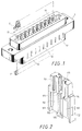
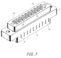
- the shell 1 of an edge connector in accordance with the present invention comprises two symmetrical rows of vertical slots 11.
- Each vertical slot 11 is formed of an upper space 111 and a lower space 112 vertically linked for positioning a metal contact spring plate 2 and a conductor clamp 3 respectively.
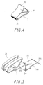
- the metal contact spring plate 2 as shown in Figure 3, comprises a bent 210 in the middle, a projecting strip 211 projected from the square bent 210, which is formed by punching, a curved clamping portion 21 at one end, a wedge portion 22 at an opposite end terminated to a tail 221 and having a side opening 220.
- the conductor clamp 3 as shown in Figure 4, is made by bending an elongated spring plate into two opposite bents 31;32 with the front end thereof stopped beneath the rear end 33 thereof.
- the insulator 41 of the electrical wire 4 is cut off at a suitable length so that the bare conductor 42 of the electrical wire 4 is directly inserted into the lower space 112 along the tail 221 of the metal contact spring plate 2.
- the bare conductor 42 of the electrical wire 4 passed through the gap between the wedge portion 22 of the metal contact spring plate 2 and the rear end 33 of the conductor clamp 3, it will be then stopped by the bent 210 of the metal contact spring plate 2.
- the front end of the bare conductor 42 of the electrical wire 4 is stopped against the bent 210 of the metal contact spring plate 2, it becomes firmly retained between the conductor clamp 3 and the metal contact spring plate 2. Therefore, the assembly process is quite simple.
- the shell 1 further comprises two rows of horizontal slots 12 on two opposite sides thereof respectively linked to either vertical slot 11.
- a rod By inserting a rod into the horizontal slot 12, it can pass through the side opening 220 on the wedge portion 22 of the respective metal contact spring plate 2 to release the respective conductor clamp 3 from the bare conductor 42 of the respective electrical wire 4, and therefore the respective electrical wire 4 can be easily removed from the shell 1.
Landscapes
- Coupling Device And Connection With Printed Circuit (AREA)
Applications Claiming Priority (2)
| Application Number | Priority Date | Filing Date | Title |
|---|---|---|---|
| US08/155,285 US5401185A (en) | 1993-11-22 | 1993-11-22 | Edge connector |
| US155285 | 1993-11-22 |
Publications (1)
| Publication Number | Publication Date |
|---|---|
| EP0654868A1 true EP0654868A1 (fr) | 1995-05-24 |
Family
ID=22554809
Family Applications (1)
| Application Number | Title | Priority Date | Filing Date |
|---|---|---|---|
| EP94102639A Withdrawn EP0654868A1 (fr) | 1993-11-22 | 1994-02-22 | Connecteur de bordure |
Country Status (3)
| Country | Link |
|---|---|
| US (1) | US5401185A (fr) |
| EP (1) | EP0654868A1 (fr) |
| CA (1) | CA2134937A1 (fr) |
Cited By (2)
| Publication number | Priority date | Publication date | Assignee | Title |
|---|---|---|---|---|
| CN110191601A (zh) * | 2019-05-30 | 2019-08-30 | 左燕 | 一种计算机网络监控装置 |
| GB2575317A (en) * | 2018-07-06 | 2020-01-08 | Johnson Electric Int Ag | Cable connector for electric parking brake actuator |
Families Citing this family (18)
| Publication number | Priority date | Publication date | Assignee | Title |
|---|---|---|---|---|
| EP0735616A3 (fr) * | 1995-03-31 | 1997-03-19 | Wieland Elektrische Industrie | Connecteur électrique, notamment pour des plaquettes de circuits |
| JPH10340745A (ja) * | 1997-06-04 | 1998-12-22 | Kyoshin Kogyo Kk | ワンタッチコネクタおよびワンタッチコネクタ組合せ体 |
| WO1999041810A1 (fr) * | 1998-02-17 | 1999-08-19 | Rambus, Inc. | Connecteur muni de contacts a configuration alternee |
| USD425865S (en) * | 1998-07-14 | 2000-05-30 | Hon Hai Precision Ind. Co., Ltd. | Electrical connector |
| KR100404629B1 (ko) | 1999-11-05 | 2003-11-07 | 마츠시타 덴끼 산교 가부시키가이샤 | 카드 커넥터 |
| JP2001313128A (ja) | 2000-04-27 | 2001-11-09 | Yamaichi Electronics Co Ltd | カードコネクタ |
| JP3825614B2 (ja) | 2000-08-08 | 2006-09-27 | 山一電機株式会社 | カードエッジコネクタ |
| JP4181307B2 (ja) | 2001-01-19 | 2008-11-12 | 山一電機株式会社 | カードコネクタ |
| JP2002237340A (ja) * | 2001-02-09 | 2002-08-23 | Yamaichi Electronics Co Ltd | カードエッジコネクタ |
| JP3464461B2 (ja) * | 2001-03-07 | 2003-11-10 | 山一電機株式会社 | コンタクト端子、および、それを備えるカード用コネクタ |
| JP2004152594A (ja) * | 2002-10-30 | 2004-05-27 | Molex Inc | 電気端子 |
| US7275966B2 (en) * | 2002-12-20 | 2007-10-02 | Molex Incorporated | Connector with heat dissipating features |
| JP2005129468A (ja) * | 2003-10-27 | 2005-05-19 | Yamaichi Electronics Co Ltd | Icカード接続用アダプタ |
| JP4210224B2 (ja) * | 2004-01-23 | 2009-01-14 | 山一電機株式会社 | 電子機器用カードコネクタ及びそれに使用されるコンタクト |
| US7329158B1 (en) * | 2006-06-30 | 2008-02-12 | Yazaki North America, Inc. | Push-lock terminal connection assembly |
| TWI645634B (zh) * | 2017-05-08 | 2018-12-21 | 進聯工業股份有限公司 | Conductive component structure for wire connection terminals |
| DE102020116380A1 (de) * | 2020-06-22 | 2021-12-23 | Phoenix Contact Gmbh & Co. Kg | Klemmeneinrichtung zum Anschließen eines elektrischen Leiters |
| TWD236455S (zh) * | 2023-07-19 | 2025-02-21 | 美商莫仕有限公司 (美國) | 線纜連接器 |
Citations (5)
| Publication number | Priority date | Publication date | Assignee | Title |
|---|---|---|---|---|
| FR1490154A (fr) * | 1965-08-24 | 1967-07-28 | Hughes Aircraft Co | Connecteurs électriques pour panneaux à circuit imprimé |
| DE1590006A1 (de) * | 1965-07-05 | 1970-05-14 | Amp Inc | Anschlussstecker fuer gedruckte Stromkreise |
| EP0052766A1 (fr) * | 1980-11-24 | 1982-06-02 | Siemens Aktiengesellschaft | Terminal sans vis |
| FR2552940A1 (fr) * | 1983-09-29 | 1985-04-05 | Siemon Co | Bloc de montage pour interconnecter des connecteurs a une plaque a circuits imprimes |
| DE3447135A1 (de) * | 1984-11-22 | 1986-05-22 | Zwicker & Hensel Elektronische Schalttechnik GmbH, 5962 Drolshagen | Schraubenlose anschluss- und verbindungsklemme fuer elektrische leitungen |
Family Cites Families (4)
| Publication number | Priority date | Publication date | Assignee | Title |
|---|---|---|---|---|
| US3015083A (en) * | 1960-01-25 | 1961-12-26 | Amphenol Borg Electronics Corp | Electrical connectors |
| US3149899A (en) * | 1962-04-16 | 1964-09-22 | United Carr Inc | Electrical contact element |
| US3422394A (en) * | 1965-08-24 | 1969-01-14 | Hughes Aircraft Co | Electrical connector |
| US3587029A (en) * | 1969-12-04 | 1971-06-22 | Litton Precision Prod Inc | Rf connector |
-
1993
- 1993-11-22 US US08/155,285 patent/US5401185A/en not_active Expired - Fee Related
-
1994
- 1994-02-22 EP EP94102639A patent/EP0654868A1/fr not_active Withdrawn
- 1994-11-02 CA CA002134937A patent/CA2134937A1/fr not_active Abandoned
Patent Citations (5)
| Publication number | Priority date | Publication date | Assignee | Title |
|---|---|---|---|---|
| DE1590006A1 (de) * | 1965-07-05 | 1970-05-14 | Amp Inc | Anschlussstecker fuer gedruckte Stromkreise |
| FR1490154A (fr) * | 1965-08-24 | 1967-07-28 | Hughes Aircraft Co | Connecteurs électriques pour panneaux à circuit imprimé |
| EP0052766A1 (fr) * | 1980-11-24 | 1982-06-02 | Siemens Aktiengesellschaft | Terminal sans vis |
| FR2552940A1 (fr) * | 1983-09-29 | 1985-04-05 | Siemon Co | Bloc de montage pour interconnecter des connecteurs a une plaque a circuits imprimes |
| DE3447135A1 (de) * | 1984-11-22 | 1986-05-22 | Zwicker & Hensel Elektronische Schalttechnik GmbH, 5962 Drolshagen | Schraubenlose anschluss- und verbindungsklemme fuer elektrische leitungen |
Cited By (3)
| Publication number | Priority date | Publication date | Assignee | Title |
|---|---|---|---|---|
| GB2575317A (en) * | 2018-07-06 | 2020-01-08 | Johnson Electric Int Ag | Cable connector for electric parking brake actuator |
| GB2575317B (en) * | 2018-07-06 | 2022-06-08 | Johnson Electric Int Ag | Actuator |
| CN110191601A (zh) * | 2019-05-30 | 2019-08-30 | 左燕 | 一种计算机网络监控装置 |
Also Published As
| Publication number | Publication date |
|---|---|
| CA2134937A1 (fr) | 1995-05-23 |
| US5401185A (en) | 1995-03-28 |
Similar Documents
| Publication | Publication Date | Title |
|---|---|---|
| US5401185A (en) | Edge connector | |
| EP0286422B1 (fr) | Pièce de contact de connecteur électrique pour plaque de circuit imprimé flexible | |
| JP2626868B2 (ja) | 電気コネクタの端子及びその製造方法 | |
| US5513082A (en) | Small lamp socket device for panel/printed board | |
| US3845455A (en) | Tubular conductor-in-slot connecting device | |
| US5928035A (en) | Printed circuit board socket | |
| US3995931A (en) | Terminal for apertured circuit panel | |
| USRE25591E (en) | figure | |
| WO2007127467A2 (fr) | Borne autodénudante | |
| EP0499431B1 (fr) | Mécanisme de retenue en forme de lance | |
| EP0458410A1 (fr) | Organe de raccordement électrique d'un conducteur électrique filiforma | |
| US20160374201A1 (en) | Printed circuit board with side access termination pads | |
| US3579170A (en) | Modular electrical connector assembly | |
| EP0349083B1 (fr) | Lampe électrique | |
| US3768062A (en) | Terminal for flexible circuits | |
| US4611874A (en) | Device for making LSA-PLUS contact with conductor wires of different types and sizes | |
| EP0777304A2 (fr) | Connecteur électrique | |
| GB2204748A (en) | Connection clip | |
| EP0145315A2 (fr) | Dispositif de connexion pour conducteurs à espacements réduits et borne de contact électrique | |
| US4323227A (en) | Connector fixture | |
| US3790918A (en) | Electrical connector | |
| US6116948A (en) | Electrical connector for terminating discrete electrical wires | |
| GB2037494A (en) | Improvements Relating to Electric Terminal Members | |
| US5951334A (en) | Junction box for printed circuits | |
| DE19539552A1 (de) | Ablagehalter für den Schirm elektr. Kabel |
Legal Events
| Date | Code | Title | Description |
|---|---|---|---|
| PUAI | Public reference made under article 153(3) epc to a published international application that has entered the european phase |
Free format text: ORIGINAL CODE: 0009012 |
|
| AK | Designated contracting states |
Kind code of ref document: A1 Designated state(s): AT BE CH DE DK ES FR GB GR IE IT LI LU MC NL PT SE |
|
| 17P | Request for examination filed |
Effective date: 19950817 |
|
| 17Q | First examination report despatched |
Effective date: 19960319 |
|
| STAA | Information on the status of an ep patent application or granted ep patent |
Free format text: STATUS: THE APPLICATION IS DEEMED TO BE WITHDRAWN |
|
| 18D | Application deemed to be withdrawn |
Effective date: 19960730 |