EP0655144B1 - Dispositif de projection d'une image couleur - Google Patents
Dispositif de projection d'une image couleur Download PDFInfo
- Publication number
- EP0655144B1 EP0655144B1 EP93917998A EP93917998A EP0655144B1 EP 0655144 B1 EP0655144 B1 EP 0655144B1 EP 93917998 A EP93917998 A EP 93917998A EP 93917998 A EP93917998 A EP 93917998A EP 0655144 B1 EP0655144 B1 EP 0655144B1
- Authority
- EP
- European Patent Office
- Prior art keywords
- light beam
- light
- substrate
- colour
- areas
- Prior art date
- Legal status (The legal status is an assumption and is not a legal conclusion. Google has not performed a legal analysis and makes no representation as to the accuracy of the status listed.)
- Expired - Lifetime
Links
- 239000000758 substrate Substances 0.000 claims abstract description 17
- 238000000576 coating method Methods 0.000 claims abstract description 15
- 239000011248 coating agent Substances 0.000 claims abstract description 14
- 239000011521 glass Substances 0.000 claims abstract description 10
- 239000003989 dielectric material Substances 0.000 claims description 7
- 230000000694 effects Effects 0.000 claims description 4
- 230000003287 optical effect Effects 0.000 claims description 3
- 238000002156 mixing Methods 0.000 claims description 2
- 229910052751 metal Inorganic materials 0.000 description 9
- 239000002184 metal Substances 0.000 description 9
- 240000005528 Arctium lappa Species 0.000 description 6
- 239000002253 acid Substances 0.000 description 4
- 238000001312 dry etching Methods 0.000 description 4
- 238000005530 etching Methods 0.000 description 4
- VYZAMTAEIAYCRO-UHFFFAOYSA-N Chromium Chemical compound [Cr] VYZAMTAEIAYCRO-UHFFFAOYSA-N 0.000 description 3
- 229910052804 chromium Inorganic materials 0.000 description 3
- 239000011651 chromium Substances 0.000 description 3
- 238000000034 method Methods 0.000 description 3
- 238000004544 sputter deposition Methods 0.000 description 3
- VYPSYNLAJGMNEJ-UHFFFAOYSA-N Silicium dioxide Chemical compound O=[Si]=O VYPSYNLAJGMNEJ-UHFFFAOYSA-N 0.000 description 2
- GWEVSGVZZGPLCZ-UHFFFAOYSA-N Titan oxide Chemical compound O=[Ti]=O GWEVSGVZZGPLCZ-UHFFFAOYSA-N 0.000 description 2
- 239000003086 colorant Substances 0.000 description 2
- 230000000295 complement effect Effects 0.000 description 1
- 238000000151 deposition Methods 0.000 description 1
- 238000001914 filtration Methods 0.000 description 1
- 238000005286 illumination Methods 0.000 description 1
- 238000010329 laser etching Methods 0.000 description 1
- 238000004519 manufacturing process Methods 0.000 description 1
- 230000000873 masking effect Effects 0.000 description 1
- 238000012986 modification Methods 0.000 description 1
- 230000004048 modification Effects 0.000 description 1
- 239000000049 pigment Substances 0.000 description 1
- 235000012239 silicon dioxide Nutrition 0.000 description 1
- 239000000377 silicon dioxide Substances 0.000 description 1
- 239000004408 titanium dioxide Substances 0.000 description 1
Images



Classifications
-
- G—PHYSICS
- G02—OPTICS
- G02B—OPTICAL ELEMENTS, SYSTEMS OR APPARATUS
- G02B5/00—Optical elements other than lenses
- G02B5/20—Filters
- G02B5/28—Interference filters
- G02B5/285—Interference filters comprising deposited thin solid films
-
- F—MECHANICAL ENGINEERING; LIGHTING; HEATING; WEAPONS; BLASTING
- F21—LIGHTING
- F21S—NON-PORTABLE LIGHTING DEVICES; SYSTEMS THEREOF; VEHICLE LIGHTING DEVICES SPECIALLY ADAPTED FOR VEHICLE EXTERIORS
- F21S10/00—Lighting devices or systems producing a varying lighting effect
- F21S10/007—Lighting devices or systems producing a varying lighting effect using rotating transparent or colored disks, e.g. gobo wheels
-
- F—MECHANICAL ENGINEERING; LIGHTING; HEATING; WEAPONS; BLASTING
- F21—LIGHTING
- F21S—NON-PORTABLE LIGHTING DEVICES; SYSTEMS THEREOF; VEHICLE LIGHTING DEVICES SPECIALLY ADAPTED FOR VEHICLE EXTERIORS
- F21S10/00—Lighting devices or systems producing a varying lighting effect
- F21S10/02—Lighting devices or systems producing a varying lighting effect changing colors
-
- F—MECHANICAL ENGINEERING; LIGHTING; HEATING; WEAPONS; BLASTING
- F21—LIGHTING
- F21V—FUNCTIONAL FEATURES OR DETAILS OF LIGHTING DEVICES OR SYSTEMS THEREOF; STRUCTURAL COMBINATIONS OF LIGHTING DEVICES WITH OTHER ARTICLES, NOT OTHERWISE PROVIDED FOR
- F21V9/00—Elements for modifying spectral properties, polarisation or intensity of the light emitted, e.g. filters
- F21V9/40—Elements for modifying spectral properties, polarisation or intensity of the light emitted, e.g. filters with provision for controlling spectral properties, e.g. colour, or intensity
-
- F—MECHANICAL ENGINEERING; LIGHTING; HEATING; WEAPONS; BLASTING
- F21—LIGHTING
- F21W—INDEXING SCHEME ASSOCIATED WITH SUBCLASSES F21K, F21L, F21S and F21V, RELATING TO USES OR APPLICATIONS OF LIGHTING DEVICES OR SYSTEMS
- F21W2131/00—Use or application of lighting devices or systems not provided for in codes F21W2102/00-F21W2121/00
- F21W2131/40—Lighting for industrial, commercial, recreational or military use
- F21W2131/406—Lighting for industrial, commercial, recreational or military use for theatres, stages or film studios
Definitions
- This invention relates to colour pattern projection apparatus for projecting a colour pattern as part of a stage lighting scheme.
- stage lighting systems it is already known in stage lighting systems to use a so called gobo, which is effectively a partially transparent slide through which a light beam is passed. With appropriate focusing arrangements, a sharp image of the gobo can be formed on an illuminated subject. It is also known to provide a mounting arrangement allowing a gobo to be rotated, so that the image referred to rotates.
- stage lighting systems are known from EP 0 253 081 A1 or EP 0 248 974 A2.
- the present invention has for its object to provide an apparatus which can be used to project a bright image in a coloured light beam and the principle problem to be overcome in such an apparatus is the provision of a transparency which can withstand the high temperatures existing in the environment of a stage light projector.
- the transparency is mounted for rotation in the light beam.
- the projector may comprise a colour changer so that light passing through clear areas of the transparency is coloured by said colour changer and light passing through the coated areas of the transparency has a colour determined by the subtractive mixing effect of the colour changer and the coated areas of the transparency.
- the transparency is preferably made by coating a dichroic filter with a layer of metal selectively removing areas of the metal coating so that the metal layer provides a mask and dry etching away the exposed dielectric layers, for example by laser etching. The remainder of the metal layer is then removed.
- the metal layer is selectively removed by acid etching initially through a photographically formed etch resist mask formed over the metal layer.
- the remainder of the metal layer is similarly removed by acid etching after removal of the photo mask.
- the transparency may be manufactured by applying a mask directly to the glass substrate and vacuum depositing the dielectric material on to the substrate through the mask.
- a series of masking and coating steps may be carried out so that different areas of the substrate have different filter properties and colour transmitted light differently.
- the transparency at the heart of the present invention is in the form of a disk of glass 10 which has one face selectively coated with areas of multi-layer dielectric film 11 which acts as a dichroic filter.
- the areas form a pattern on the glass disk.
- the selective coating of the disk is effected by coating it all over with multi-layer dielectric film in known manner by sputtering on to it alternate layers of high and low refractive index dielectric materials such as titanium dioxide and silicon dioxide. Other dielectric materials can of course be used. Parts of the film are then selectively removed. To assist in such removal, a further coating of metal film 12 (such as chromium) is first formed on the dielectric film and a coating of a photo-resist film 13 is provided over the metal film 12 ( Figure 1a). The desired pattern is photo-exposed on the photo-resist film which is then developed so that unexposed areas of the film are washed off ( Figure 1b).
- metal film 12 such as chromium
- FIG. 2 illustrates an alternative procedure by means of which a transparency can be made with complementary areas of two different colours.
- a glass substrate 110 is first provided over the whole of one face with a multi-layer dielectric coating 111 of a first colour and this is then covered by a rigid mask 112 mechanically clamped to the substrate.
- This mask 112 is formed with holes in a pattern matching the required pattern of areas from which the first colour is to be removed. Removal is effected as above by dry etching using a layer.
- the second colour is now applied by sputtering on multiple layers of dielectric materials 113 through the holes in the mask.
- the mask 112 is finally removed to provide the two colour transparency.
- a third colour could similarly be applied by dry etching and sputtering through a different mechanically clamped mask and so on.
- dichroic filter coatings could be provided on both sides of a glass substrate and differently shaped transparent patterns dry etched into opposite sides giving a three colour effect by subtractive colour filtering where coloured areas overlap.
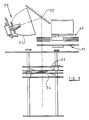
- FIGS 3 and 4 illustrate the use of the transparency described above in a light beam projector, intended primarily for use in the lighting of stage shows and the like.
- the projector comprises a light source 20 which comprises a high temperature arc lamp. This is located at the focus of a reflector 21 forming, together with a plane reflector 22 and a pair of lens elements 23, 24 an optical system.
- the lens elements 23, 24 are independently movable axially of the light beam reflected by plane reflector 22 and can focus on a distant surface an image of the pattern on the transparency which is mounted on a multiple gobo wheel arrangement 25.
- the gobo wheel arrangement 25 is shown in more detail in Figure 4 and includes a main wheel 26 rotatable about its own axis which is spaced from and parallel to the axis of the light beam.
- the wheel 26 is formed with a series of equi-angularly spaced circular openings over some or all of which differently designed transparencies are mounted.
- Each transparency is mounted in a circular rim 27 carried in bearings 28 on the wheel 26 so that the transparency can be rotated on its own axis, which is coincident with the beam axis when the particular transparency is located at working position.
- the wheel 26 can be turned by a remotely controlled motor 29 to position any of the transparencies or an unused opening in the wheel 26 at the working position.
- a gobo-rotator motor 30 is provided for rotating all the transparencies simultaneous.
- Each of the rims 27 has external gear teeth and these all mesh with a driving gear 31 mounted co-axially with the wheel 26.
- the motor 30 drives this gear 31 via a gear 32 on its shaft.
- the focused image of the colour pattern formed on the transparency at the working position can be rotated.
- the focused image will, in the absence of any other colour filters in the system comprise a pattern of illumination in white and a single colour of light.
- the projector also includes, however, a colour changer system 40, utilising three independently rotatable colour wheels each of which carries a plurality of differently coloured dichroic filter elements.
- a colour changer system 40 utilising three independently rotatable colour wheels each of which carries a plurality of differently coloured dichroic filter elements.
- a dielectric layer selectively applied to a transparent substrate to form a transparency is advantageous in that a dichroic filter operates without absorbing an excessive amount of heat from the light beam passing through it. Transparencies formed from selectively applied pigments do not have this advantage.
Landscapes
- Physics & Mathematics (AREA)
- Engineering & Computer Science (AREA)
- General Engineering & Computer Science (AREA)
- Spectroscopy & Molecular Physics (AREA)
- General Physics & Mathematics (AREA)
- Optics & Photonics (AREA)
- Optical Filters (AREA)
- Projection Apparatus (AREA)
- Mechanical Light Control Or Optical Switches (AREA)
Abstract
Claims (7)
- Projecteur de faisceau lumineux à des fins d'éclairage de scène, comprenant:caractérisé en ce que:une source de lumière (20);un système optique (21, 22, 23, 24) pour concentrer la lumière en provenance de ladite source de lumière selon un faisceau; etun substrat en verre optiquement transparent (10, 110) dans ledit faisceau comportant sur lui un revêtement (11, 111) en un matériau diélectrique, lequel joue le rôle de filtre dichroïque qui opère pour réfléchir la lumière de façon sélective,(a) ledit substrat en verre (10, 110) a seulement des zones sélectionnées de lui-même qui sont munies dudit revêtement de telle sorte que seulement une partie du faisceau lumineux transmis soit ainsi colorée; et(b) ledit substrat en verre est situé par rapport audit système optique de telle sorte qu'une image colorée focalisée desdites zones sélectionnées puisse être formée sur une surface distante.
- Projecteur de faisceau lumineux selon la revendication 1, caractérisé en outre en ce qu'une pluralité de différentes zones (111, 113) du substrat sont revêtues de couches formées différemment en un matériau diélectrique afin d'assurer un effet multicouleur.
- Projecteur de faisceau lumineux selon la revendication 2, dans lequel il y a deux de ces différentes zones qui sont conformées de façon complémentaire l'une par rapport à l'autre.
- Projecteur de faisceau lumineux selon la revendication 1, dans lequel des couches formées différemment en un matériau diélectrique permettant de transmettre une lumière colorée différemment sont formées de façon sélective sur des côtés opposés du substrat.
- Projecteur de faisceau lumineux selon la revendication 4, dans lequel des zones revêtues sur des côtés opposés du substrat sont conformées différemment.
- Projecteur de faisceau lumineux selon l'une quelconque des revendications précédentes, dans lequel le substrat est monté de manière à pouvoir tourner autour de l'axe du faisceau lumineux de manière à provoquer une rotation de ladite image focalisée.
- Projecteur de faisceau lumineux selon l'une quelconque des revendications précédentes, comprenant en outre un dispositif de changement de couleur (40) de telle sorte que la lumière qui passe au travers de zones claires du substrat (10) soit colorée par ledit dispositif de changement de couleur et que la lumière qui passe au travers des zones revêtues du substrat présente une couleur qui est déterminée par l'effet de mélange soustractif du dispositif de changement de couleur et des zones revêtues en ce qui concerne la transparence.
Applications Claiming Priority (3)
| Application Number | Priority Date | Filing Date | Title |
|---|---|---|---|
| GB9217392 | 1992-08-15 | ||
| GB929217392A GB9217392D0 (en) | 1992-08-15 | 1992-08-15 | Colour image protection apparatus |
| PCT/GB1993/001700 WO1994004951A1 (fr) | 1992-08-15 | 1993-08-11 | Dispositif de projection d'une image couleur |
Publications (2)
| Publication Number | Publication Date |
|---|---|
| EP0655144A1 EP0655144A1 (fr) | 1995-05-31 |
| EP0655144B1 true EP0655144B1 (fr) | 2001-11-14 |
Family
ID=10720425
Family Applications (1)
| Application Number | Title | Priority Date | Filing Date |
|---|---|---|---|
| EP93917998A Expired - Lifetime EP0655144B1 (fr) | 1992-08-15 | 1993-08-11 | Dispositif de projection d'une image couleur |
Country Status (8)
| Country | Link |
|---|---|
| US (1) | US5795058A (fr) |
| EP (1) | EP0655144B1 (fr) |
| AU (1) | AU4724593A (fr) |
| CA (1) | CA2142619C (fr) |
| DE (1) | DE69331145T2 (fr) |
| DK (1) | DK0655144T3 (fr) |
| GB (1) | GB9217392D0 (fr) |
| WO (1) | WO1994004951A1 (fr) |
Families Citing this family (11)
| Publication number | Priority date | Publication date | Assignee | Title |
|---|---|---|---|---|
| DE10200872A1 (de) * | 2002-01-11 | 2003-07-31 | Unaxis Balzers Ag | Strukturiertes optisches Element und Herstellung eines Solchen |
| GB2294909B (en) * | 1994-11-14 | 1996-10-23 | High End Systems Inc | Acid etched gobo |
| US5711889A (en) * | 1995-09-15 | 1998-01-27 | Buchsbaum; Philip E. | Method for making dichroic filter array |
| HUP9904476A2 (hu) * | 1999-12-03 | 2002-01-28 | Péter Danczkay | Beállítható háromdimenziós (3D), többszínű fényhullám-generátor |
| US6379025B1 (en) * | 2000-03-31 | 2002-04-30 | Pacfab, Inc. | Submersible lighting fixture with color wheel |
| IT1317661B1 (it) * | 2000-05-22 | 2003-07-15 | Coemar Spa | Proiettore luminoso particolarmente per la proiezione di immagini adimensioni variabili e ad infiniti colori |
| TW548437B (en) * | 2001-03-02 | 2003-08-21 | Unaxis Balzers Ag | Optical component and its production method as well as optical switch |
| CN2498623Y (zh) * | 2001-10-18 | 2002-07-03 | 王庆洪 | 户外照明图案电脑灯 |
| US6729734B2 (en) * | 2002-04-01 | 2004-05-04 | Hewlett-Packard Development Company, L.P. | System for enhancing the quality of an image |
| CA2729352A1 (fr) * | 2008-06-30 | 2010-01-07 | Thomas Hough | Generateur de motif de lumiere a haute resolution sur un substrat transparent |
| EP3992525A4 (fr) | 2019-06-26 | 2022-08-17 | Guangzhou Haoyang Electronic Co., Ltd. | Plaque à effet capable d'éviter une déformation à haute température et lampe de scène comprenant celle-ci |
Family Cites Families (6)
| Publication number | Priority date | Publication date | Assignee | Title |
|---|---|---|---|---|
| US3914464A (en) * | 1971-04-19 | 1975-10-21 | Optical Coating Laboratory Inc | Striped dichroic filter and method for making the same |
| GB1441745A (en) * | 1972-10-06 | 1976-07-07 | Emi Ltd | Manufacture of a pattern on a substrate |
| JPS59152407A (ja) * | 1983-02-18 | 1984-08-31 | Toppan Printing Co Ltd | 多層干渉膜フイルタ−の製造法 |
| CA1228225A (fr) * | 1984-11-09 | 1987-10-20 | National Research Council Of Canada | Methode de fabrication de dispositifs d'authentification a interference optique |
| US4800474A (en) * | 1986-05-15 | 1989-01-24 | Vari-Lite, Inc. | Color wheel assembly for lighting equipment |
| US4779176A (en) * | 1986-07-16 | 1988-10-18 | Vari-Lite, Inc. | Light pattern generator |
-
1992
- 1992-08-15 GB GB929217392A patent/GB9217392D0/en active Pending
-
1993
- 1993-08-11 WO PCT/GB1993/001700 patent/WO1994004951A1/fr not_active Ceased
- 1993-08-11 AU AU47245/93A patent/AU4724593A/en not_active Abandoned
- 1993-08-11 DK DK93917998T patent/DK0655144T3/da active
- 1993-08-11 CA CA002142619A patent/CA2142619C/fr not_active Expired - Lifetime
- 1993-08-11 EP EP93917998A patent/EP0655144B1/fr not_active Expired - Lifetime
- 1993-08-11 US US08/381,967 patent/US5795058A/en not_active Expired - Lifetime
- 1993-08-11 DE DE69331145T patent/DE69331145T2/de not_active Expired - Fee Related
Also Published As
| Publication number | Publication date |
|---|---|
| WO1994004951A1 (fr) | 1994-03-03 |
| EP0655144A1 (fr) | 1995-05-31 |
| CA2142619C (fr) | 2000-02-22 |
| DE69331145D1 (de) | 2001-12-20 |
| CA2142619A1 (fr) | 1994-03-03 |
| GB9217392D0 (en) | 1992-09-30 |
| DK0655144T3 (da) | 2001-12-10 |
| US5795058A (en) | 1998-08-18 |
| DE69331145T2 (de) | 2002-06-20 |
| AU4724593A (en) | 1994-03-15 |
Similar Documents
| Publication | Publication Date | Title |
|---|---|---|
| US3748975A (en) | Apparatus for and method of correcting a defective photomask | |
| EP0655144B1 (fr) | Dispositif de projection d'une image couleur | |
| US5825548A (en) | Cross-fading color filter and system | |
| AU586095B2 (en) | Light pattern generator | |
| JPS6079331A (ja) | カラ−液晶表示装置の製造方法 | |
| US5620817A (en) | Fabrication of self-aligned attenuated rim phase shift mask | |
| JPS58501202A (ja) | 高密度記録媒体及びこれを製造する方法 | |
| US5329335A (en) | Method and apparatus for projection exposure | |
| US5001038A (en) | Process for photoimaging a three dimensional printed circuit substrate | |
| KR940000904B1 (ko) | 사진평판 마스크 정렬장치 및 그 방법 | |
| US4444456A (en) | Holographic method and apparatus for transformation of a light beam into a line source of required curvature and finite numerical aperture | |
| JPS62189468A (ja) | ホトマスク,及びそれを用いた投影露光方法、並びにホトマスクの製造方法 | |
| WO1993015439A1 (fr) | Diapositives couleurs permanentes sur substrats uniques et leurs procedes de fabrication | |
| JP2011022529A (ja) | 光源装置及び露光装置 | |
| EP1385054B1 (fr) | Procédé de fabrication d'un disque à filtre chromatique | |
| US7333278B2 (en) | Manufacturing method of color wheel, and color wheel fabricated thereby and incorporated in color wheel assembly and image display apparatus | |
| US5806951A (en) | Multi-substrate gobo | |
| JPS5950518A (ja) | 投影プリント方法 | |
| JPH03100655A (ja) | エマルジョンマスク等の欠陥修正装置 | |
| JP2668834B2 (ja) | 露光装置 | |
| CN216408672U (zh) | 一种多彩光学系统 | |
| KR970004421B1 (ko) | 반도체 노광장치 | |
| JPS57107034A (en) | Exposure equipment for contraction projection | |
| JPS5854495B2 (ja) | 位置合わせ方法および光学装置 | |
| JPH0621771B2 (ja) | 透明電極膜パターンの検出方法 |
Legal Events
| Date | Code | Title | Description |
|---|---|---|---|
| PUAI | Public reference made under article 153(3) epc to a published international application that has entered the european phase |
Free format text: ORIGINAL CODE: 0009012 |
|
| 17P | Request for examination filed |
Effective date: 19950224 |
|
| AK | Designated contracting states |
Kind code of ref document: A1 Designated state(s): DE DK FR GB IT |
|
| 17Q | First examination report despatched |
Effective date: 19960611 |
|
| RTI1 | Title (correction) |
Free format text: COLOUR IMAGE PROJECTION APPARATUS |
|
| GRAG | Despatch of communication of intention to grant |
Free format text: ORIGINAL CODE: EPIDOS AGRA |
|
| GRAG | Despatch of communication of intention to grant |
Free format text: ORIGINAL CODE: EPIDOS AGRA |
|
| GRAH | Despatch of communication of intention to grant a patent |
Free format text: ORIGINAL CODE: EPIDOS IGRA |
|
| GRAH | Despatch of communication of intention to grant a patent |
Free format text: ORIGINAL CODE: EPIDOS IGRA |
|
| GRAA | (expected) grant |
Free format text: ORIGINAL CODE: 0009210 |
|
| AK | Designated contracting states |
Kind code of ref document: B1 Designated state(s): DE DK FR GB IT |
|
| RIC1 | Information provided on ipc code assigned before grant |
Free format text: 7G 02B 5/28 A, 7F 21S 10/00 B |
|
| REG | Reference to a national code |
Ref country code: DK Ref legal event code: T3 |
|
| REF | Corresponds to: |
Ref document number: 69331145 Country of ref document: DE Date of ref document: 20011220 |
|
| REG | Reference to a national code |
Ref country code: GB Ref legal event code: IF02 |
|
| ET | Fr: translation filed | ||
| PLBE | No opposition filed within time limit |
Free format text: ORIGINAL CODE: 0009261 |
|
| STAA | Information on the status of an ep patent application or granted ep patent |
Free format text: STATUS: NO OPPOSITION FILED WITHIN TIME LIMIT |
|
| 26N | No opposition filed | ||
| PGFP | Annual fee paid to national office [announced via postgrant information from national office to epo] |
Ref country code: IT Payment date: 20070830 Year of fee payment: 15 Ref country code: DE Payment date: 20071001 Year of fee payment: 15 |
|
| PGFP | Annual fee paid to national office [announced via postgrant information from national office to epo] |
Ref country code: FR Payment date: 20070817 Year of fee payment: 15 |
|
| REG | Reference to a national code |
Ref country code: FR Ref legal event code: ST Effective date: 20090430 |
|
| PG25 | Lapsed in a contracting state [announced via postgrant information from national office to epo] |
Ref country code: IT Free format text: LAPSE BECAUSE OF NON-PAYMENT OF DUE FEES Effective date: 20080811 Ref country code: FR Free format text: LAPSE BECAUSE OF NON-PAYMENT OF DUE FEES Effective date: 20080901 Ref country code: DE Free format text: LAPSE BECAUSE OF NON-PAYMENT OF DUE FEES Effective date: 20090303 |
|
| PGFP | Annual fee paid to national office [announced via postgrant information from national office to epo] |
Ref country code: GB Payment date: 20101013 Year of fee payment: 18 |
|
| PGFP | Annual fee paid to national office [announced via postgrant information from national office to epo] |
Ref country code: DK Payment date: 20110210 Year of fee payment: 18 |
|
| GBPC | Gb: european patent ceased through non-payment of renewal fee |
Effective date: 20110811 |
|
| REG | Reference to a national code |
Ref country code: DK Ref legal event code: EBP |
|
| PG25 | Lapsed in a contracting state [announced via postgrant information from national office to epo] |
Ref country code: DK Free format text: LAPSE BECAUSE OF NON-PAYMENT OF DUE FEES Effective date: 20110831 |
|
| PG25 | Lapsed in a contracting state [announced via postgrant information from national office to epo] |
Ref country code: GB Free format text: LAPSE BECAUSE OF NON-PAYMENT OF DUE FEES Effective date: 20110811 |