EP0655155B1 - Befestigungsvorrichtung für das gehäuse einer elektronischen anzeige - Google Patents
Befestigungsvorrichtung für das gehäuse einer elektronischen anzeige Download PDFInfo
- Publication number
- EP0655155B1 EP0655155B1 EP94918906A EP94918906A EP0655155B1 EP 0655155 B1 EP0655155 B1 EP 0655155B1 EP 94918906 A EP94918906 A EP 94918906A EP 94918906 A EP94918906 A EP 94918906A EP 0655155 B1 EP0655155 B1 EP 0655155B1
- Authority
- EP
- European Patent Office
- Prior art keywords
- rail
- housing
- intermediate part
- projection
- designed
- Prior art date
- Legal status (The legal status is an assumption and is not a legal conclusion. Google has not performed a legal analysis and makes no representation as to the accuracy of the status listed.)
- Expired - Lifetime
Links
Images

Classifications
-
- G—PHYSICS
- G09—EDUCATION; CRYPTOGRAPHY; DISPLAY; ADVERTISING; SEALS
- G09F—DISPLAYING; ADVERTISING; SIGNS; LABELS OR NAME-PLATES; SEALS
- G09F3/00—Labels, tag tickets, or similar identification or indication means; Seals; Postage or like stamps
- G09F3/08—Fastening or securing by means not forming part of the material of the label itself
- G09F3/18—Casings, frames or enclosures for labels
- G09F3/20—Casings, frames or enclosures for labels for adjustable, removable, or interchangeable labels
- G09F3/204—Casings, frames or enclosures for labels for adjustable, removable, or interchangeable labels specially adapted to be attached to a shelf or the like
-
- G—PHYSICS
- G09—EDUCATION; CRYPTOGRAPHY; DISPLAY; ADVERTISING; SEALS
- G09F—DISPLAYING; ADVERTISING; SIGNS; LABELS OR NAME-PLATES; SEALS
- G09F3/00—Labels, tag tickets, or similar identification or indication means; Seals; Postage or like stamps
- G09F3/08—Fastening or securing by means not forming part of the material of the label itself
- G09F3/18—Casings, frames or enclosures for labels
- G09F3/20—Casings, frames or enclosures for labels for adjustable, removable, or interchangeable labels
- G09F3/208—Electronic labels, Labels integrating electronic displays
Definitions
- the present invention relates to a device for fixing housings of electronic modules allowing the display of information, such as prices or the like, in retail stores or any other site, such as for example storage areas. or production factories.
- This installation makes it possible to replace conventional cardboard labels, with liquid crystal display modules which receive their display instructions from a management unit which centralizes all the information relating to the various products exhibited in the same store.
- An important advantage of such an installation is that it makes it possible to avoid the long manipulations that a complete updating of the prices of the various items exhibited in a store requires, such as a large area.
- These display modules are intended to take place along the edges of the shelves of the shelves in which the articles are placed.
- the means for fixing the modules' housings consist of rails which run along the shelving boards and which include slides in which complementary grooves are fitted which are presented by said housings.
- the boxes are manually translated into these rails until they are positioned at the level of the articles to which they correspond.
- a main object of the invention is therefore to propose a fixing device which makes it possible to solve this problem.
- Document GB-2 249 854 already discloses a device for fixing at least one electronic module box for displaying information relating to a product displayed in a store, in particular a retail store, comprising a rail intended to receive the housing and an intermediate piece which carries at least one elastic locking element having at least one projection intended to cooperate with a groove that the rail presents to ensure the maintenance of said housing relative to said rail, the housing and this intermediate piece having additional means for fixing said housing to said part.
- the invention aims to overcome these drawbacks.
- the solution according to the invention consists in particular in that the locking element carries a hook intended to cooperate with a complementary relief of the intermediate piece to maintain said locking element in a retracted position, by opposing its elastic stress, and where the projection is then disengaged relative to the groove of the rail with which it cooperates, the intermediate piece having an elastic branch which, when the housing and the intermediate piece are placed on the rail, is pushed back, by contact with the bottom of said rail, on the hook so as to disengage the latter from the complementary relief with which it cooperates, the locking element then elastically pushing the projection in the groove of the rail.
- the operator has only to arm the locking element, then to exert a simple pushing force on the box once the latter and its intermediate part presented on the rail .
- the fixing device proposed by the invention also has the advantage of being adaptable to shelves of shelves of different dimensions, and in particular to shelves of different thicknesses.
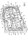
- the device shown in Figure 1 allows the attachment to a shelving board 2, a housing 1 of a display module forming an electronic label.
- This module has a screen 3 which, when the housing 1 is fixed on the board 2, is parallel to the edge 4 of the board 2 and is visible to a consumer passing between the shelves.
- This display module is part of an installation of the type which has been described in the above-mentioned French patent application FR-2,658,645.
- the fixing device mainly comprises a retaining profile 5 and a part 6 intermediate between this profile 5 and the housing 1.
- the retaining profile 5 is a part constituted by a shelf 10 for supporting said profile 5 on a shelving board and by a receiving rail 5a which has mainly a U-shaped section.
- This rail 5a has a bottom 7, bordered longitudinally by two sides 8 and 9 which are designated throughout the text by lower side 8 and upper side 9, with reference to their respective positions when the profile 5 is in place on the shelving board 2.
- the tablet 10 runs along said rail 5a, extending from the bottom 7 perpendicularly to the latter, on the side opposite to the upper edge 9.
- This retaining profile 5 is intended to be mounted on the shelving board 2 so that the shelf 10 and the bottom 7 are respectively in abutment on the upper surface of the board 2 and on the edge 4.
- the fixing of the profile 5 on the board 2 is carried out by riveting.
- the faces of the shelf 10 and the bottom 7 which are opposite their bearing faces have longitudinal grooves 11 intended to receive and conceal the heads of the rivets (not shown).
- the lower side 8 is conventionally provided with a flat groove 12 of C-shaped section, which is open on the face of this side 8 which is opposite to the upper side 9.
- This groove 12 thus forms a slide which, when the profile 5 is in place, is open at the bottom and can carry, for example, a support made of folded PVC material for advertising elements (of the type commonly called STOP-RAYON).
- the rail 5a also has two grooved longitudinal inner grooves, referenced by 13, which are carried one by the lower edge 8, the other by the upper edge 9. These two grooved grooves 13 extend opposite one of the other over the entire length of the rail 5a, and are located in the immediate vicinity of the bottom 7.
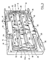
- the intermediate part 6 which is shown there is constituted by a plate 14 and an elastic locking element 21, which will be described later in more detail.
- the plate 14 is of rectangular outline. It has a bottom 14a and external 15 and internal 16 patterns in excess thickness between which is intended to come to fit the element 21.
- the external width of the plate 14 is slightly less than the distance between the opposite faces of the sides 8 and 9. Its length is substantially that of a housing 1.
- the external pattern 15 surrounds the frame 14 over a major part of its outline. It is interrupted along each of the length sides of the frame 14 by an opening 17 centered on the side to which it corresponds and extending over substantially a third on this side (proportion which is of course given only for information and may vary). On either side of this opening 17, the pattern 15 is reinforced and extends in particular from the side of the frame 14 over a thickness greater than along the widths of said frame 14.
- the parts of the outer pattern 15 which extend along the length sides of the plate 14 carry two flanges 18 which extend respectively along each of these sides, perpendicular to the bottom 14a of the plate 14. Each of these two flanges 18 carries ribs 35 in projecting towards the inside of the frame, which are intended to engage in corresponding grooves that the housing 1 presents, to hold said housing 1 relative to the intermediate element 6.
- the internal pattern 16 comprises an elongated rectangular rib 16a, the length sides of which are parallel to the length sides of the plate 14, this rib 16a being centered on the center of this plate 14.
- the widths of this rectangular rib 16a are extended by each side of the lengths of said rib by ribs 16b which stop opposite the reinforced portions of the outer pattern 15.
- the space between the outer pattern 15 and such a rib 16b is the same for each of these four ribs 16b.
- Four rounded protrusions 20 projecting from the widths of the rectangular rib 16a extend the lengths of this rib 16a beyond said widths.
- One of the lengths of the rectangular rib 16a is interrupted in its middle part by an opening 16c.
- the bottom of the frame 14 still carries two studs 19 (Figure 2) of a height less than the height of the patterns 15 and 16. These two studs 19 are disposed at each end of the longitudinal central axis of the frame 14 and are juxtaposed to the portions of pattern 15 which extend the along the widths of the frame 14. The space between each of these studs 19 and the rectangular rib 16a is substantially identical to the space between the ribs 16b and the pattern 15.
- the elastic locking element 21 has two uprights 22 connecting together two longitudinal crosspieces 23. These uprights 22 and these crosspieces 23 together define a frame 24 which fits between the patterns 15 and 16 and which is held by friction with respect to those -this.
- the ends of the ribs 16b are located at the interior walls of the corners of the frame 24, the walls delimiting the exterior corners of the frame 24 being in contact with the reinforced portions of the external pattern 15 in excess thickness.
- the uprights 22 are then in contact through their internal walls with the rounded protrusions 20.
- Each upright 22 carries a plate 24a forming an ear which extends from this upright towards the outside of the frame.
- a plate 24a forming an ear comes to bear on one of the studs 19 when the element 21 is in place on the plate 14.
- Each longitudinal cross member 23 carries a tab 25 and a tongue 26 which are each flat and parallel to the median plane of the frame 24.
- a tab 25 extends from the cross member 23 which carries it towards the outside of the frame 24.
- a tongue 26 extends from its cross member 23 towards the inside of the frame 24. Such tab 25 and tongue 26 are centered with respect to the length of the cross member 23 which carries them.
- a tab 25 extends over a third of the length of the crosspiece 23 which carries it. It has on its edge furthest from the cross member 23 which carries the grooves 27 which are intended to cooperate, as will be described later in more detail, with the grooves of the grooves 13. On a central portion of such a tab 25, these grooves are delimited by an inclined face 28 which extends from the crests of the grooves 27 towards the crosspiece 23 which carries this tab 25, from one of the faces of the tab 25 towards the other of its faces.
- the grooves 27 on either side of this inclined face 28 are closed on one side, by a flat wall 29 which extends the face of the tab 25 which is opposite to the side of the tab 25 where the crests of the grooves of the pan 28.
- the flange 18 which is closest to the opening 16c also has an inclined flap 18a which is intended to extend the flap 28 of the tab 25 which is located to the right of this flange 18, when the longitudinal cross member 23 which carries this tab 25 is not stressed in bending.
- the tongue 26 carried by the longitudinal cross member 23 furthest from the opening 16c is a spacer which comes to bear on the rectangular rib 16a. It prevents this longitudinal cross member 23 from being stressed in bending.
- the other tab 26 ends with a hook 30 facing the bottom 14a and intended to come to cooperate with the edge of the opening 16c.
- the outline which is delimited on the bottom 14a by the rectangular rib 16a is hollowed out.
- the widths of the rectangular rib 16a carry, at the level of the recess thus defined, two flat elastic branches referenced by 31 and 32. They extend one and the other parallel to the sides of the lengths of the bottom 14, respectively d 'one of the widths of the rib 16a up to substantially the center of the latter.
- the branch 31 ends at its end furthest from the width side which carries it by two lugs 33 and 34 which project in relation to said branch, respectively on the side of the latter intended to be opposite the bottom 7 and on the side thereof intended to be in look at the bottom of the housing 1.
- the lug 33 is less tall than the lug 34.
- the housing 1 has on its bottom a recess (not shown), intended to receive the lug 34, as well as an inclined groove 37 (Figure 1) intended to guide the lug 34 to this recess.
- the branch 32 ends in turn with a plate 36 which is slightly projecting with respect to the face of the bottom 14 intended to be opposite the bottom 7 and which is located exactly in line with the area occupied by the hook 30 when the tongue 26 which is terminated by this hook 30 is pushed back through the opening 16c.
- an operator places the retaining profile 5 on the shelving board 2 and fixes it thereon, for example by riveting the bottom 7 and the shelf 10 on the edge 4 and the upper face of the board 2 who have undergone a pre-drilling.
- the rivets are regularly distributed along the length of the board 2 and are arranged so that their heads are at the level of the grooves 11.
- the profile 5 can be mounted on shelving boards of different dimensions, and in particular of different thickness.
- the elastic locking element 21 is placed on the plate 14 as follows: the frame 24 is presented with a slight inclination relative to the plate 14, so as to fit one of the legs 25 into the opening 18 which is closest to that of the lengths of the rectangular rib 16a which has no opening. Then the frame 21 is folded down between the exterior and interior patterns 15 and 16, by bending the crosspiece 23 which carries the other tab 25, so as to introduce the latter into the opening 18 which matches ( Figure 2).
- the housing 1 is then slid along the intermediate element 6, between the flanges 18, so that the ribs 35 engage in the complementary grooves that the housing 1 has.
- the groove 37 guides the lug 34 to the recess that the housing has for receiving it.
- the lug 33 of the tongue 31 is pushed back by contact with the bottom 7, so that the lug 34 is forced into the recess that has the housing 1.
- the housing 1 is thus locked relative to the intermediate piece 6.
- the operator has a tool which allows him to interpose a blade between the grooves of the upper tab 25 and the grooves of the groove upper 13 of the holding profile.
- the wall 29 and the inclined face 28 are used to guide the blade to the crest of the grooves 27 of the tab 25.
- the operator disengages these grooves from the upper grooves of the holding profile. 5. It can then remove from the rail 5a the assembly that constitutes the intermediate piece 6 and the housing 1.
- the lug 34 is no longer locked in the corresponding recess in the bottom of the housing 1.
- the operator slides the housing 1 with respect to the intermediate piece 6.
- the various parts of the device which has just been described are produced by molding, for example PVC.
- the bottom of one or other of the two grooves 13 can be made of a more flexible material (rubber, flexible PVC or other material) than the rest of the profile 5 and into which the grooves 27 penetrate to take hold .
- a profile 5 is obtained by using coextrusion methods known to those skilled in the art. This softer material can be placed on or in place of the teeth. It can fill the throat, be laminated or fluted.
- Profile 5 intermediate piece 6 and housing can be personalized by particular colors, by varying the colors of the materials in which these three elements are made, or by plating on the bottom 7 of the rail 5a a colored strip.
- the teeth of the rail can be produced separately.
- the teeth of the rail can be replaced by foam, rubber or any other fastening material fulfilling the blocking function of the intermediate piece.
- the teeth of the intermediate piece can themselves be replaced by any other locking means. They can in particular, either in the upper part, in the lower part, or both, be made of a plastic material different from that of the rest of the intermediate piece. This biplasticity can be achieved by adding an additional part.
- grooves at the bottom of the rail may have another arrangement and, in particular, be located for example between the lower and upper edges of the rail, or even at the front of the rail.
- the shape of the support profile can be very variable. In the example described, the shape of the profile allows it to be adapted on a board with a vertical edge. Its shape could be different for basket wire or glass supports (glass shelf, for example).
- the fixing of the profile on its support can be achieved by other means than by riveting and in particular by gluing or by adhesive tapes.
Landscapes
- Physics & Mathematics (AREA)
- General Physics & Mathematics (AREA)
- Engineering & Computer Science (AREA)
- Theoretical Computer Science (AREA)
- Connection Of Plates (AREA)
- Casings For Electric Apparatus (AREA)
- Assembled Shelves (AREA)
- Mounting Components In General For Electric Apparatus (AREA)
- Devices For Indicating Variable Information By Combining Individual Elements (AREA)
Claims (9)
- Befestigungsvorrichtung für wenigstens ein Gehäuse (1) eines elektronischen Moduls für die Anzeige von Informationen in bezug auf ein Produkt, das in einem Geschäft, insbesondere einem Einzelhandelsgeschäft ausgestellt ist, mit einer Schiene (5a), die dafür bestimmt ist, das Gehäuse (1) und ein Zwischenstück (6) aufzunehmen, das wenigstens ein elastisches Verriegelungselement (21) trägt, das wenigstens einen Vorsprung aufweist, der dafür bestimmt ist, mit einer Nut, die die Schiene (5a) aufweist, zusammenzuarbeiten, um den Halt des Gehäuses (1) in bezug auf die Schiene (5a) zu sichern, wobei das Gehäuse (1) und das Zwischenstück (6) komplementäre Mittel (35) für die Befestigung des Gehäuses (1) an dem Zwischenstück (6) aufweisen, dadurch gekennzeichnet, daß das Verriegelungselement (21) einen Haken (30) trägt, der dafür bestimmt ist, mit einem komplementären Relief des Zwischenstücks (6) zusammenzuarbeiten, um das Verriegelungselement (21) in einer eingezogenen Position, in der es sich seiner elastischen Belastung widersetzt, zu halten, wobei in diesem Fall der Vorsprung (25) in bezug auf die Nut (13) der Schiene, mit der er zusammenarbeitet, ausgerückt ist, wobei das Zwischenstück (6) einen elastischen Arm (32) aufweist, der beim Aufsetzen des Gehäuses (1) und des Zwischenstücks (6) auf die Schiene (5a) durch die Berührung mit dem Boden (7) der Schiene auf den Haken (30) zurückgedrückt wird, um diesen von dem komplementären Relief, mit dem er zusammenarbeitet, zu lösen, wobei in diesem Fall das Verriegelungselement (21) den Vorsprung elastisch in die Nut der Schiene (5a) zurückdrückt.
- Vorrichtung nach Anspruch 1, dadurch gekennzeichnet, daß die Schiene (5a) einen Boden (7) und zwei Flanken (8, 9), die den Boden (7) in Längsrichtung einfassen, sowie zwei innere Nuten (13) aufweist, die an der einen und der anderen der Flanken (8, 9) ausgebildet sind und die sich längs des Bodens (7) in dessen unmittelbarer Nähe erstrecken.
- Vorrichtung nach einem der Ansprüche 1 oder 2, dadurch gekennzeichnet, daß das Zwischenstück (6) einen elastischen Arm (32) trägt, der in einem Nocken (34) endet, wobei der Boden des Gehäuses (1) eine Ausnehmung für die Aufnahme des Nockens (34) aufweist, wobei der Arm (32) beim Aufsetzen des Gehäuses (1) und des Zwischenstücks (6) auf die Schiene (5a) durch die Berührung mit dem Boden (7) der Schiene derart zurückgedrückt wird, daß der Nokken (34) in die Ausnehmung eingreift, um das Gehäuse (1) in bezug auf das Zwischenstück (6) zu verriegeln.
- Vorrichtung nach einem der vorhergehenden Ansprüche, dadurch gekennzeichnet, daß wenigstens ein Vorsprung (25) eine Riffelung (27) aufweist, die dafür bestimmt ist, mit komplementären Mitteln, die an derjenigen Nut (13), die mit dem besagten Vorsprung (25) zusammenarbeitet, ausgebildet sind, zusammenzuarbeiten, um das Gehäuse (1) in Längsrichtung in bezug auf die Schiene (5a) zu halten.
- Vorrichtung nach Anspruch 4, dadurch gekennzeichnet, daß die Riffelung (27) über die gesamte Länge von wenigstens einer Nut (13) der Schiene verteilt ist.
- Vorrichtung nach Anspruch 4, dadurch gekennzeichnet, daß der Boden von wenigstens einer Nut der Schiene aus einem Material besteht, in das die Riffelung des geriffelten Vorsprungs eindringen kann, um Halt zu finden.
- Vorrichtung nach Anspruch 2 allein oder in Verbindung mit einem der Ansprüche 3 bis 6, dadurch gekennzeichnet, daß die untere Flanke (8) der Schiene (5a) eine flache Nut (12) aufweist, die auf derjenigen Seite dieser Flanke (8), die von der oberen Flanke (9) abgewandt ist, offen ist und dafür bestimmt ist, Träger für Werbung oder ähnliches aufzunehmen und zu tragen.
- Vorrichtung nach Anspruch 2 allein oder in Verbindung mit einem der Ansprüche 3 bis 7, zum Befestigen des Gehäuses (1) an einem Regalbrett (2), dadurch gekennzeichnet, daß die Schiene (5a) ein Teil eines Profils (5) ist, das zudem eine Platte (10) aufweist, die sich im wesentlichen in rechtem Winkel in bezug auf den Boden (7) der Schiene (5a) erstreckt, wobei die Platte (10) und der Boden (7) der Schiene (5a) dafür bestimmt sind, sich an jeweils der oberen Seite und dem Rand des Brettes (4) abzustützen.
- Vorrichtung nach Anspruch 8, dadurch gekennzeichnet, daß die Schiene (5a) und die Platte (10) durch Nietung an dem Regalbrett (2) befestigt sind und in Längsrichtung verlaufende Vertiefungen (11) zur Aufnahme der Nietköpfe aufweisen.
Applications Claiming Priority (3)
| Application Number | Priority Date | Filing Date | Title |
|---|---|---|---|
| FR9307097A FR2706665B1 (fr) | 1993-06-11 | 1993-06-11 | Dispositif pour la fixation d'un boîtier d'affichage électronique. |
| FR9307097 | 1993-06-11 | ||
| PCT/FR1994/000688 WO1994029832A1 (fr) | 1993-06-11 | 1994-06-10 | Dispositif pour la fixation d'un boitier d'affichage electronique |
Publications (2)
| Publication Number | Publication Date |
|---|---|
| EP0655155A1 EP0655155A1 (de) | 1995-05-31 |
| EP0655155B1 true EP0655155B1 (de) | 1997-04-16 |
Family
ID=9448067
Family Applications (1)
| Application Number | Title | Priority Date | Filing Date |
|---|---|---|---|
| EP94918906A Expired - Lifetime EP0655155B1 (de) | 1993-06-11 | 1994-06-10 | Befestigungsvorrichtung für das gehäuse einer elektronischen anzeige |
Country Status (9)
| Country | Link |
|---|---|
| US (1) | US5611512A (de) |
| EP (1) | EP0655155B1 (de) |
| JP (1) | JPH08500455A (de) |
| AU (1) | AU669075B2 (de) |
| CA (1) | CA2142200A1 (de) |
| DE (1) | DE69402669T2 (de) |
| ES (1) | ES2102864T3 (de) |
| FR (1) | FR2706665B1 (de) |
| WO (1) | WO1994029832A1 (de) |
Families Citing this family (16)
| Publication number | Priority date | Publication date | Assignee | Title |
|---|---|---|---|---|
| FR2732145A1 (fr) * | 1995-03-23 | 1996-09-27 | Visioplast Sarl | Dispositif de support d'etiquettes electroniques |
| CA2247909A1 (en) * | 1996-06-21 | 1997-12-24 | James A. Bacnik | Holder for electronic information carrier |
| US5853196A (en) * | 1996-06-24 | 1998-12-29 | Ncr Corporation | Electronic shelf labels for mounting in c channels of retail shelves and method for mounting |
| US6622410B2 (en) | 1998-02-20 | 2003-09-23 | Illinois Tool Works Inc. | Attachment bracket for a shelf-edge display system |
| FR2780193B1 (fr) | 1998-06-18 | 2001-12-14 | Store Elect Sys Elect Shelf La | Dispositif de fixation d'etiquette electronique, notamment d'affichage de prix, sur une extremite de broche de support d'articles |
| US6553702B1 (en) | 1999-03-05 | 2003-04-29 | Fasteners For Retail, Inc. | Holder for an electronic price label |
| US6409132B2 (en) | 1999-04-30 | 2002-06-25 | Display Edge Technology, Ltd. | Attachment bracket for a rail |
| US6367752B1 (en) | 1999-10-20 | 2002-04-09 | Ncr Corporation | Electronic price label mounting apparatus |
| US6698701B1 (en) * | 2000-11-15 | 2004-03-02 | Ncr Corporation | Electronic shelf label mounting apparatus |
| USD511547S1 (en) * | 2003-03-04 | 2005-11-15 | Pricer Ab | Electronic label |
| US7159352B1 (en) | 2003-03-11 | 2007-01-09 | Daniel Lefebvre | End cap apparatus |
| US7455081B2 (en) * | 2003-03-12 | 2008-11-25 | Fasteners For Retail, Inc. | Holder for an electronic price label |
| SE524793C2 (sv) * | 2003-03-13 | 2004-10-05 | Hl Display Ab | System och hållare för elektronisk informationsdisplay |
| US20070090073A1 (en) * | 2005-10-26 | 2007-04-26 | The Stanley Works | System for displaying a sample of a product |
| US10706749B1 (en) * | 2019-08-09 | 2020-07-07 | K-International, Inc. | Shelf label holder with breakaway guide and method |
| JP2022027434A (ja) * | 2020-07-31 | 2022-02-10 | 日本電気株式会社 | 棚札取付装置 |
Family Cites Families (13)
| Publication number | Priority date | Publication date | Assignee | Title |
|---|---|---|---|---|
| US3034756A (en) * | 1959-09-21 | 1962-05-15 | Illum A Rail Inc | Display device |
| US3610425A (en) * | 1960-02-24 | 1971-10-05 | Foster Products Inc | Article support and display devices |
| GB1546566A (en) * | 1975-07-17 | 1979-05-23 | Arrow Hart Europe Ltd | Base for electrical components |
| US4179138A (en) * | 1978-03-17 | 1979-12-18 | Jet Press, Inc. | Rail strip and locking device |
| EP0009277B1 (de) * | 1978-09-14 | 1984-04-18 | Gist-Brocades N.V. | Kombinierter Impfstoff, der gegen die Newcastle-Krankheit und gegen die durch Adeno-ähnliche Viren verursachte Eierlege-Krankheit wirksam ist, Verfahren zu seiner Herstellung, Adeno-ähnliche- und Newcastle-Krankheit-Virusstämme |
| US4357768A (en) * | 1981-03-06 | 1982-11-09 | Brett De Dube | Display card holder |
| US4466592A (en) * | 1982-05-24 | 1984-08-21 | Janson Kenneth D | Sign holder |
| US4939861A (en) * | 1987-12-28 | 1990-07-10 | Telepanel, Inc. | Shelf tag moulding attachment assembly |
| US4909464A (en) * | 1989-07-10 | 1990-03-20 | Henschel-Steinau, Inc. | Deflectable price channel-mounted sign holder |
| FR2658645B1 (fr) * | 1990-02-16 | 1994-10-07 | Sitour Electronic Systems | Installation comportant un ensemble de modules d'affichage commandes a distance. |
| GB2249854A (en) * | 1990-10-17 | 1992-05-20 | Sainsbury J Plc | Electronic labels |
| AT394913B (de) * | 1990-11-13 | 1992-07-27 | Tiedemann Roman | Einrichtung zur loesbaren befestigung von an lagerbehaeltern, lagerregalen, ladenmoebeln od. dgl. anzubringenden anzeigeschildern |
| US5452874A (en) * | 1994-06-30 | 1995-09-26 | Kozloff; Matthew S. | Retainer device for an electronic signalling device |
-
1993
- 1993-06-11 FR FR9307097A patent/FR2706665B1/fr not_active Expired - Fee Related
-
1994
- 1994-06-10 JP JP7501421A patent/JPH08500455A/ja active Pending
- 1994-06-10 DE DE69402669T patent/DE69402669T2/de not_active Expired - Fee Related
- 1994-06-10 ES ES94918906T patent/ES2102864T3/es not_active Expired - Lifetime
- 1994-06-10 EP EP94918906A patent/EP0655155B1/de not_active Expired - Lifetime
- 1994-06-10 US US08/387,902 patent/US5611512A/en not_active Expired - Fee Related
- 1994-06-10 WO PCT/FR1994/000688 patent/WO1994029832A1/fr not_active Ceased
- 1994-06-10 AU AU70020/94A patent/AU669075B2/en not_active Ceased
- 1994-06-10 CA CA002142200A patent/CA2142200A1/fr not_active Abandoned
Also Published As
| Publication number | Publication date |
|---|---|
| AU669075B2 (en) | 1996-05-23 |
| AU7002094A (en) | 1995-01-03 |
| WO1994029832A1 (fr) | 1994-12-22 |
| US5611512A (en) | 1997-03-18 |
| DE69402669T2 (de) | 1997-11-27 |
| FR2706665B1 (fr) | 1995-09-08 |
| JPH08500455A (ja) | 1996-01-16 |
| FR2706665A1 (fr) | 1994-12-23 |
| ES2102864T3 (es) | 1997-08-01 |
| DE69402669D1 (de) | 1997-05-22 |
| CA2142200A1 (fr) | 1994-12-22 |
| EP0655155A1 (de) | 1995-05-31 |
Similar Documents
| Publication | Publication Date | Title |
|---|---|---|
| EP0655155B1 (de) | Befestigungsvorrichtung für das gehäuse einer elektronischen anzeige | |
| EP1835828A1 (de) | Vorrichtung zur verteilung mindestens eines anzeigezubehörteils auf einer oberfläche mit guter anzeige | |
| EP0338872B1 (de) | Vorrichtung zur Ausstellung von Waren und verschiedenen Produkten, insbesondere in Geschäften | |
| EP0657672B1 (de) | Vorrichtung für die Stossverbindung von perforierten Abschnitten eines Kabelkanals | |
| FR2904459A1 (fr) | Profile porte-etiquette ou profile mere pour fixation de porte-etiquette amovible. | |
| EP0243247B1 (de) | Durch elastisches Ineinandergreifen befestigbares Schild | |
| WO2009019394A1 (fr) | Systeme d'etiquetage electronique | |
| FR2502923A1 (fr) | Dispositif de support de console, notamment pour presentoirs | |
| FR2660633A1 (fr) | Dispositif contre la separation d'objets devant etre exposes ensemble a la vente, tels que des chaussures. | |
| WO2011010003A1 (fr) | Dispositif de fixation universelle d'une etiquette electronique | |
| FR2784781A1 (fr) | Dispositif separateur d'articles | |
| FR2780193A1 (fr) | Dispositif de fixation d'etiquette electronique, notamment d'affichage de prix, sur une extremite de broche de support d'articles | |
| FR2881331A1 (fr) | Dispositif de separation amovible et reglable pour etageres de presentoirs | |
| EP1634512A1 (de) | Präsentationsregal zur Lagerung kleiner Lasten zur grossflächigen Verteilung | |
| FR2841362A1 (fr) | Dispositif de balisage et de presentation d'informations pour presentoir d'objets | |
| EP1844460B1 (de) | Schiene zum anbringen von hilfseinrichtungen an der vorderseite von tischen an verkaufspunkten und assoziierte kommunikationsmedium-einrichtung | |
| FR2476996A1 (fr) | Vitrine d'exposition comportant un cadre et un panneau superieurs rectangulaires | |
| FR2590143A1 (fr) | Dispositif de presentation a etiquetage amovible | |
| FR2688665A1 (fr) | Unite formant bac modulable amovible pour la presentation de produits et meuble comprenant un tel bac. | |
| FR2518389A1 (fr) | Coffret-presentoir a couvercle articule | |
| FR2649821A1 (fr) | Crochet porte-etiquette | |
| FR2657242A3 (fr) | Presentoir de vente pour chaines, tuyaux et articles analogues. | |
| FR2950235A1 (fr) | Presentoir de vente d'objets | |
| BE394742A (de) | ||
| FR2481909A1 (fr) | Presentoir demontable notamment pour montures de lunettes |
Legal Events
| Date | Code | Title | Description |
|---|---|---|---|
| PUAI | Public reference made under article 153(3) epc to a published international application that has entered the european phase |
Free format text: ORIGINAL CODE: 0009012 |
|
| AK | Designated contracting states |
Kind code of ref document: A1 Designated state(s): BE DE ES GB IT NL SE |
|
| 17P | Request for examination filed |
Effective date: 19950220 |
|
| GRAG | Despatch of communication of intention to grant |
Free format text: ORIGINAL CODE: EPIDOS AGRA |
|
| 17Q | First examination report despatched |
Effective date: 19960701 |
|
| GRAH | Despatch of communication of intention to grant a patent |
Free format text: ORIGINAL CODE: EPIDOS IGRA |
|
| GRAH | Despatch of communication of intention to grant a patent |
Free format text: ORIGINAL CODE: EPIDOS IGRA |
|
| GRAA | (expected) grant |
Free format text: ORIGINAL CODE: 0009210 |
|
| AK | Designated contracting states |
Kind code of ref document: B1 Designated state(s): BE DE ES GB IT NL SE |
|
| REF | Corresponds to: |
Ref document number: 69402669 Country of ref document: DE Date of ref document: 19970522 |
|
| GBT | Gb: translation of ep patent filed (gb section 77(6)(a)/1977) |
Effective date: 19970624 |
|
| REG | Reference to a national code |
Ref country code: ES Ref legal event code: FG2A Ref document number: 2102864 Country of ref document: ES Kind code of ref document: T3 |
|
| PLBE | No opposition filed within time limit |
Free format text: ORIGINAL CODE: 0009261 |
|
| STAA | Information on the status of an ep patent application or granted ep patent |
Free format text: STATUS: NO OPPOSITION FILED WITHIN TIME LIMIT |
|
| 26N | No opposition filed | ||
| PGFP | Annual fee paid to national office [announced via postgrant information from national office to epo] |
Ref country code: ES Payment date: 19990622 Year of fee payment: 6 |
|
| PGFP | Annual fee paid to national office [announced via postgrant information from national office to epo] |
Ref country code: NL Payment date: 19990630 Year of fee payment: 6 |
|
| PGFP | Annual fee paid to national office [announced via postgrant information from national office to epo] |
Ref country code: SE Payment date: 19990709 Year of fee payment: 6 |
|
| PG25 | Lapsed in a contracting state [announced via postgrant information from national office to epo] |
Ref country code: SE Free format text: LAPSE BECAUSE OF NON-PAYMENT OF DUE FEES Effective date: 20000611 |
|
| PG25 | Lapsed in a contracting state [announced via postgrant information from national office to epo] |
Ref country code: ES Free format text: THE PATENT HAS BEEN ANNULLED BY A DECISION OF A NATIONAL AUTHORITY Effective date: 20000612 |
|
| PG25 | Lapsed in a contracting state [announced via postgrant information from national office to epo] |
Ref country code: NL Free format text: LAPSE BECAUSE OF NON-PAYMENT OF DUE FEES Effective date: 20010101 |
|
| EUG | Se: european patent has lapsed |
Ref document number: 94918906.2 |
|
| NLV4 | Nl: lapsed or anulled due to non-payment of the annual fee |
Effective date: 20010101 |
|
| PGFP | Annual fee paid to national office [announced via postgrant information from national office to epo] |
Ref country code: DE Payment date: 20011127 Year of fee payment: 8 |
|
| PGFP | Annual fee paid to national office [announced via postgrant information from national office to epo] |
Ref country code: GB Payment date: 20011128 Year of fee payment: 8 |
|
| PGFP | Annual fee paid to national office [announced via postgrant information from national office to epo] |
Ref country code: BE Payment date: 20011213 Year of fee payment: 8 |
|
| REG | Reference to a national code |
Ref country code: GB Ref legal event code: IF02 |
|
| REG | Reference to a national code |
Ref country code: ES Ref legal event code: FD2A Effective date: 20020204 |
|
| PG25 | Lapsed in a contracting state [announced via postgrant information from national office to epo] |
Ref country code: GB Free format text: LAPSE BECAUSE OF NON-PAYMENT OF DUE FEES Effective date: 20020610 |
|
| PG25 | Lapsed in a contracting state [announced via postgrant information from national office to epo] |
Ref country code: BE Free format text: LAPSE BECAUSE OF NON-PAYMENT OF DUE FEES Effective date: 20020630 |
|
| BERE | Be: lapsed |
Owner name: SITOUR ELECTRONIC SYSTEMS *SES Effective date: 20020630 |
|
| PG25 | Lapsed in a contracting state [announced via postgrant information from national office to epo] |
Ref country code: DE Free format text: LAPSE BECAUSE OF NON-PAYMENT OF DUE FEES Effective date: 20030101 |
|
| GBPC | Gb: european patent ceased through non-payment of renewal fee |
Effective date: 20020610 |
|
| PG25 | Lapsed in a contracting state [announced via postgrant information from national office to epo] |
Ref country code: IT Free format text: LAPSE BECAUSE OF NON-PAYMENT OF DUE FEES Effective date: 20050610 |