EP0655227A2 - Procédé pour la fabrication de prothèses dentaires - Google Patents
Procédé pour la fabrication de prothèses dentaires Download PDFInfo
- Publication number
- EP0655227A2 EP0655227A2 EP94116610A EP94116610A EP0655227A2 EP 0655227 A2 EP0655227 A2 EP 0655227A2 EP 94116610 A EP94116610 A EP 94116610A EP 94116610 A EP94116610 A EP 94116610A EP 0655227 A2 EP0655227 A2 EP 0655227A2
- Authority
- EP
- European Patent Office
- Prior art keywords
- friction element
- electrode
- primary part
- secondary part
- attachment
- Prior art date
- Legal status (The legal status is an assumption and is not a legal conclusion. Google has not performed a legal analysis and makes no representation as to the accuracy of the status listed.)
- Withdrawn
Links
- 238000004519 manufacturing process Methods 0.000 title claims abstract description 18
- 238000009760 electrical discharge machining Methods 0.000 claims abstract description 17
- 229910052751 metal Inorganic materials 0.000 claims abstract description 4
- 239000002184 metal Substances 0.000 claims abstract description 4
- 238000000034 method Methods 0.000 claims description 18
- 239000004033 plastic Substances 0.000 claims description 4
- 229920003023 plastic Polymers 0.000 claims description 4
- 238000013459 approach Methods 0.000 claims description 3
- 238000003754 machining Methods 0.000 description 3
- 210000004513 dentition Anatomy 0.000 description 2
- 238000013461 design Methods 0.000 description 2
- 230000006866 deterioration Effects 0.000 description 2
- 238000003780 insertion Methods 0.000 description 2
- 230000037431 insertion Effects 0.000 description 2
- 229910000510 noble metal Inorganic materials 0.000 description 2
- 238000012545 processing Methods 0.000 description 2
- 230000036346 tooth eruption Effects 0.000 description 2
- RTAQQCXQSZGOHL-UHFFFAOYSA-N Titanium Chemical compound [Ti] RTAQQCXQSZGOHL-UHFFFAOYSA-N 0.000 description 1
- 239000002131 composite material Substances 0.000 description 1
- 238000011161 development Methods 0.000 description 1
- 230000018109 developmental process Effects 0.000 description 1
- 239000000463 material Substances 0.000 description 1
- 239000007769 metal material Substances 0.000 description 1
- 238000003801 milling Methods 0.000 description 1
- 238000012805 post-processing Methods 0.000 description 1
- 239000003566 sealing material Substances 0.000 description 1
- 238000007493 shaping process Methods 0.000 description 1
- 239000010936 titanium Substances 0.000 description 1
- 229910052719 titanium Inorganic materials 0.000 description 1
Images


Classifications
-
- A—HUMAN NECESSITIES
- A61—MEDICAL OR VETERINARY SCIENCE; HYGIENE
- A61C—DENTISTRY; APPARATUS OR METHODS FOR ORAL OR DENTAL HYGIENE
- A61C13/00—Dental prostheses; Making same
- A61C13/0003—Making bridge-work, inlays, implants or the like
-
- A—HUMAN NECESSITIES
- A61—MEDICAL OR VETERINARY SCIENCE; HYGIENE
- A61C—DENTISTRY; APPARATUS OR METHODS FOR ORAL OR DENTAL HYGIENE
- A61C13/00—Dental prostheses; Making same
- A61C13/225—Fastening prostheses in the mouth
- A61C13/265—Sliding or snap attachments
- A61C13/2653—Sliding attachments
Definitions
- the invention relates to a method for producing dental prosthesis parts, such as crowns, bridges, partial or full dentures, with at least one metallic primary part and a secondary part, also made of metal, releasably fastened to it, the primary part and secondary part connecting at least one connecting elements that fit together
- dental prosthesis parts such as crowns, bridges, partial or full dentures
- at least one metallic primary part and a secondary part also made of metal, releasably fastened to it, the primary part and secondary part connecting at least one connecting elements that fit together
- Have attachments that are arranged at a defined distance from each other, so that a defined space is formed between guide surfaces of the connecting elements, into which a friction element is fitted.
- the connecting elements of the attachment are designed with their guide surfaces in the correct position with respect to one another and with a precise fit, so that sufficient friction between the guide surfaces is ensured for the friction element and the secondary part does not unintentionally detach from the primary part.
- the quality of such dental work therefore depends crucially on the shape and position of the guide surfaces.
- the connecting elements on the primary part and on the secondary part were previously formed and / or milled when the part was being cast. Due to unavoidable tolerances, however, it could not essentially be guaranteed that after the tooth replacement part had been attached to the dentition, the guide surfaces of the connecting elements would later be exactly aligned with one another and would assume their desired position. In most cases, time-consuming rework was necessary so that the required alignment and arrangement of the guide surfaces could be achieved with the desired precision.
- the invention is therefore based on the object of improving the method of the type mentioned in such a way that it requires little time and is therefore inexpensive, but at the same time ensures the required precision and can be used in a dental laboratory without problems.
- the essential idea of the invention is therefore to roughly design the attachment in a first step during the production of the primary part and the secondary part, to the extent that the primary part and the secondary part can be assembled without a friction element with the aid of the connecting elements before in a second step, in which the secondary part is arranged in the correct position on the primary part, the guide surfaces of the attachment are given their final Finnish as well as their desired orientation and arrangement by post-machining by means of spark erosion.
- the connecting elements of the attachment Due to the rough design of the connecting elements of the attachment in the first step, it is already possible to connect the primary part and the secondary part to one another - at least provisionally - for the purpose of adapting the dental prosthesis part to the denture model.
- the connecting elements are only prepared in such a way that when the secondary part is arranged in the correct position on the primary part, the distance between the guide surfaces is generally less than a defined target distance, but in no case may it be greater than this.
- the primary part and secondary part can generally only be assembled without arranging the friction element, since the space for receiving the friction element generally does not yet have the required dimensions; nevertheless, there is already so much tolerance within the attachment that it is possible to adjust the position of the secondary part on the primary part by slightly shifting these parts against one another. In this way, the correct position of the primary part and secondary part on the bit and on each other can be determined individually for each bit.
- the guide surfaces of the attachment Only when the correct arrangement of the secondary part on the primary part has been determined for the individual dentition, are the guide surfaces of the attachment according to the invention finished to form the defined space for accommodating the friction element. Only through this finishing or finishing or “finishing” do the guide surfaces of the attachment receive their desired exact and tension-free alignment and correct position according to the situation in the mouth, which means that the defined distance between the guide surfaces on the primary part and secondary part and thus the defined space is formed, in which the friction element can then be fitted.
- the guide surfaces are finished by means of spark erosion, the dimensions of the electrode used essentially corresponding to the dimensions of the friction element to be used subsequently. However, it goes without saying that the dimensions of the electrode with regard to the spark gap must be slightly smaller than the dimensions of the friction element.
- the space between the guide surfaces of the connecting elements is thus eroded in its desired, defined dimensions, in order to subsequently be able to accommodate the friction element in such a way that sufficient friction occurs between the guide surfaces of the attachment for a secure fixation of the secondary part on the primary part.
- this measure according to the invention has the advantage that the attachment can then be formed precisely to the individual application, without later having to fear a deterioration in the fit of the secondary part on the primary part.
- the finishing of the attachment is carried out in a particularly simple and uncomplicated manner by using the spark erosion method according to the invention.
- the spark erosion process offers a number of serious advantages.
- the shape of the guide surfaces of the connecting elements and Thus, the defined intermediate space to be formed between them and thus also the friction element to be inserted in them can be freely selected by appropriate shaping of the electrode.
- the processing is carried out gently and without pressure on the part to be machined, so that there is no fear of deformation of the mostly thin side walls of the machined parts.
- the guide surfaces can also be worked into hard metallic materials such as noble metals, non-noble metals and especially titanium without difficulty.
- the electrode is driven in the sliding direction of the attachment between its connecting elements.
- the guide surface of the one connecting element on the primary part is reworked with a first surface of the electrode and the guide surface of the other connecting element on the secondary part is reworked simultaneously with a second surface of the electrode.
- the guide surface of one connection element is formed with a convex shape and the guide surface of the other connection element with a corresponding concave shape.
- a method is particularly preferred in which a recess and an attachment fitting into the recess are provided for forming the attachment, so that the guide surfaces are formed by the inner surface of the recess and the outer surface of the attachment.
- the secondary part when the secondary part is arranged in the correct position on the primary part, between the Recess and the approach seated in the electrode driven in such a way that with a first surface of the electrode, the outer surface of the approach and with a second surface of the electrode, the inner surface of the recess is simultaneously finished.
- the attachment preferably has a partially or fully cylindrical section and the friction element is designed as an open or closed sleeve, in an advantageous further development the attachment is designed as a cylinder which is laterally seated on a web and the friction element is designed as a slot sleeve.
- Dental prosthesis parts are usually produced with at least two attachments for connecting the primary part and the secondary part, the attachments and recesses of the attachments then having to be worked out running parallel to one another, since otherwise there would be fitting problems.
- the simultaneous finishing of parallel attachments with the desired precision can be achieved in a simple manner with the aid of the invention, in that the electrodes only have to be arranged and moved parallel to one another.
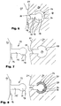
- FIGS. 1 to 8 which comprises a primary part 10, which can preferably be a crown made of metal, and a secondary part 20.
- a rod part 12 which forms the one connecting element of the attachment, is modeled on the primary part 10.
- the rod part 12 has a rectangular, plate-shaped foot 14 with which it is attached to the primary part 10.
- a web 15 rises from the foot 14, on which in turn a partially cylindrical section 16 is arranged with its long side.
- the diameter of the part-cylindrical section 16 is larger than the thickness of the web 15.
- a recess 24 is formed in the secondary part 20, which forms the other connecting element of the attachment.
- the recess 24 has a first section open to the side 21 of the secondary part 20 directed towards the primary part 10, with two parallel inner walls 26 and an inner second section widening with respect to the first section, the inner surface 28 of which is concave and in the exemplary embodiment shown has approximately the shape of a 270 ° circular section in cross section. Accordingly, the concave inner surface 28 of the recess 24 in the form of a three-quarter circle cylinder with an axis running parallel to the walls 26.
- the cavity delimited by the inner surface 28 is dimensioned such that it receives the part-cylindrical section 16 of the rod part 12 seated on the primary part 10 without contact by a gap 30 (see FIGS. 5 and 6) between the outer surface 18 of the part-cylindrical section 16 and the inner surface 28 of the recess 24 remains.
- the distance between the two parallel inner walls 26 corresponds approximately to the thickness of the web 15 of the rod part 12, so that when the rod part 12 is inserted into the recess 24, there is only a relatively small amount of play between the web 15 and the parallel inner walls 26.
- the rod part 12 and the recess 24 together form a attachment for connecting the primary part 10 and the secondary part 20, the concave inner surface 28 of the recess 24 and the convex outer surface 18 of the partially cylindrical section 16 of the rod part 12 forming the guide surfaces of the attachment.
- the surfaces 18 and 28 run at a defined distance from one another, so that, as already mentioned above, a defined arcuate gap 30 is formed between them, as can be seen in particular from FIGS. 5 and 6.
- a friction element 32 is fitted into this curved gap 30, the dimensions of which correspond to the dimensions of the curved gap 30, as can be clearly seen in FIG. 8, so that it is seated in the gap 30 in a fixed and rotationally fixed manner.
- the friction element 32 is shown in detail in FIG. 4. It essentially has the shape of a slotted sleeve. With its outer convex surface 34, the friction element 32 bears against the concave inner surface 28 of the recess 24, while the concave inner surface 36 of the friction element 32 bears against the convex outer surface 18 of the part-cylindrical section 16 of the rod part 12.
- the primary part 10 and the secondary part 20 are produced, which can be done, for example, by milling and / or spark erosion. With the manufacture of the primary part 10 and the secondary part 20, the rod part 12 and the recess 24 are also formed at the same time. The rod part 12 can also be produced separately and then modeled or attached to the primary part 10.
- the rod part 12 on the primary part 10 and the recess 24 in the secondary part 20 are roughly pre-processed in a first step such that they generally do not yet get their final dimensions as shown in the figures by the rod part 12 on the primary part 10 in this manufacturing step generally a little larger and the recess 24 in the secondary part 20 is generally a little smaller than in the final state shown.
- the attachment thus formed has a certain tolerance, since the rod part 12 is only loosely seated in the recess 24. As a result, the rod part 12 can be displaced to a certain extent within the cutout 24, so that the secondary part 20 connected to the primary part 10 can be aligned with the primary part 10 and adjusted to the desired position.
- the convex outer surface 18 of the part-cylindrical section 16 of the rod part 12 and the concave inner surface 28 of the recess 24 become joint in one operation by spark erosion post-processed by means of an electrode 50 shown in FIG.
- the dimensions of the electrode 50 essentially correspond to the friction element 32, although the electrode 50 should have slightly smaller cross-sectional dimensions because of the spark gap which arises during spark erosion.
- the electrode 50 is now driven in the sliding direction of the attachment into the already existing gap 30 between the rod part 12 and the recess 24 by means of spark erosion, with the inner surface 52 of the electrode 50 (see FIG. 4), the concave outer surface 18 of the partially cylindrical section 16 of the Rod part 12 on the primary part 10 (cf. in particular FIG. 6) and with the outer surface 54 of the electrode 50 (cf. FIG. 4) the concave inner surface 28 of the recess 24 in the secondary part 20 (cf. in particular FIG. 6) is reworked. With this measure, the rod part 12 and the recess 24 get their final shape and thus their final finish, so that the surfaces 18 and 28 now get the desired course and are arranged at the desired, defined distance from each other.
- the arc-shaped gap 30 now also has the desired, defined dimensions which now allow the slot-sleeve-shaped friction element 32 to be fitted into the intermediate space 30 at 0 ° to the direction of insertion, ie, stress-free directly in the direction of insertion, as indicated in FIG. 8.
- the outer surface 18 of the part-cylindrical section 16 of the rod part 12 is polished on the primary part.
- the attachment With the inserted friction element 32, which can be made of plastic with a high coefficient of friction, the attachment is finished and now enables a precise fit of the secondary part 20 on the primary part 10, without later having to fear a deterioration of the fit.
- the remaining part of the gap 30 can be sealed with a suitable sealing material such as e.g. Composite material can be closed.
- FIGS. 9 to 15 show a second embodiment of an attachment. This embodiment differs from the first embodiment described with reference to FIGS. 1 to 8 in that, instead of a cutout 24 machined directly into the secondary part 20, a separate piece of pipe is used, which is attached to a secondary part, not shown here.
- the rod part 112 of this embodiment shown in FIG. 9 has a circular disk-shaped foot 114, from which a cylindrical section 116 rises. With the foot 114, the rod part 112 or the like to a primary part, not shown. modeled.
- FIG. 10 shows the already mentioned pipe section 122, the cavity 124 of which is open on both end faces and is cylindrical in shape.
- the diameter of the cavity 124 is dimensioned such that the cavity 124 can receive the cylindrical section 116 of the rod part 112 without contact.
- the tube piece 124 is provided with two radially extending connecting arms 127, which are used for holding in the secondary part or for connecting two secondary parts with a primary part lying in between to serve.
- the connecting arms 127 are preferably modeled on the pipe section 122.
- the rod part 112 and the pipe section 122 now form the attachment for connecting the primary part and the secondary part, the convex outer surface 118 of the cylindrical section 116 of the rod part 112 and the concave inner surface 128 of the cavity 124 of the pipe section 122 forming the guide surfaces of the attachment.
- the surfaces 118 and 128 run at a defined distance from one another, so that a defined annular gap 130 is formed between them, as can be seen in FIG. 14.
- a friction element 132 is fitted into this annular gap 130, the dimensions of which correspond to the dimensions of the annular gap 30, as can be seen in FIG.
- the friction element 132 is shown in detail in FIG. 11. It essentially has the shape of a cylindrical sleeve. With its outer surface 134, the friction element 132 bears against the concave inner surface 128 of the tube piece 122, while the inner surface 136 of the friction element 132 bears against the convex outer surface 118 of the rod part 112.
- the rod part 112 and the tube piece 122 are also formed or attached, however, they are roughly pre-machined so that the cylindrical portion 116 of the rod part 112 and the cavity 124 of the tube piece 122 generally do not yet have their final shape Obtain dimensions as shown in the figures.
- the cylindrical section 116 of the rod part 112 on the primary part is generally somewhat larger and the cavity 124 of the tube piece 122 on the secondary part is less than in the final state shown.
- the attachment thus formed has a certain tolerance as in the first embodiment, since the rod part 112 is only loosely seated in the cavity 124 of the tube piece 122. As a result, the rod part 112 can be displaced to a certain extent within the tube piece 122, so that a certain alignment and adjustment of the connection between the primary part and the secondary part is still possible.
- the convex outer surface 118 of the cylindrical section 116 of the rod part 112 and the concave surface 128 of the cavity 124 of the tube piece 122 are reworked together in one operation by spark erosion by means of an electrode 152 shown in FIG. As can be seen from a comparison of FIGS.
- the dimensions of the electrode 150 essentially correspond to that of the friction element 132. Accordingly, the electrode 150 has the same sleeve shape as the friction element 132. However, the electrode 150 should be taken into account because of the spark gap which arises during spark erosion also have slightly smaller cross-sectional dimensions in this embodiment.
- the electrode 150 is now driven in the sliding direction of the attachment between the rod part 112 and the tube piece 122, with the inner surface 152 of the sleeve-shaped electrode 150 (see FIG. 13), the outer surface 118 of the rod part 112 (see FIG. 9) and with the outer surface 154 of the electrode 150 (see FIG. 13), the inner wall 124 of the pipe section 122 (see FIG. 10) is reworked.
- the cylindrical portion 116 of the rod part 112 and the cavity 124 of the tube piece 122 get their final shape and thus their final finish, so that the surfaces 118 and 128 now receive the desired course and the desired arrangement and at the desired, defined distance from one another are arranged.
- the annular gap 130 now also has the desired, defined dimensions which allow the friction element 132 to be fitted into the annular gap 130, as shown in FIG. 15.
- the friction element 132 used in the second embodiment is preferably made of the same material as the friction element 32 of the first embodiment.
- the secondary part can also be attached to the primary part with two or more attachments. In this case, make sure that the attachments are aligned parallel to each other to enable the secondary part to be easily fixed to the primary part.
- this is not a problem with the method described above, since the electrodes then only need to be guided parallel to one another.
Landscapes
- Health & Medical Sciences (AREA)
- Oral & Maxillofacial Surgery (AREA)
- Dentistry (AREA)
- Epidemiology (AREA)
- Life Sciences & Earth Sciences (AREA)
- Animal Behavior & Ethology (AREA)
- General Health & Medical Sciences (AREA)
- Public Health (AREA)
- Veterinary Medicine (AREA)
- Dental Prosthetics (AREA)
Applications Claiming Priority (2)
| Application Number | Priority Date | Filing Date | Title |
|---|---|---|---|
| DE4336397 | 1993-10-26 | ||
| DE19934336397 DE4336397A1 (de) | 1993-10-26 | 1993-10-26 | Verfahren zur Herstellung von Zahnersatzteilen |
Publications (2)
| Publication Number | Publication Date |
|---|---|
| EP0655227A2 true EP0655227A2 (fr) | 1995-05-31 |
| EP0655227A3 EP0655227A3 (fr) | 1995-08-02 |
Family
ID=6500980
Family Applications (1)
| Application Number | Title | Priority Date | Filing Date |
|---|---|---|---|
| EP94116610A Withdrawn EP0655227A3 (fr) | 1993-10-26 | 1994-10-21 | Procédé pour la fabrication de prothèses dentaires. |
Country Status (2)
| Country | Link |
|---|---|
| EP (1) | EP0655227A3 (fr) |
| DE (1) | DE4336397A1 (fr) |
Family Cites Families (3)
| Publication number | Priority date | Publication date | Assignee | Title |
|---|---|---|---|---|
| DE3118890A1 (de) * | 1981-05-13 | 1983-01-27 | Hans-Albert 2857 Langen Kreylos | Verfahren zur herstellung von zahnersatzteilen |
| EP0175054A1 (fr) * | 1982-04-05 | 1986-03-26 | Rübeling, Günter | Procédé pour la fabrication de prothèses dentaires |
| DE3801994A1 (de) * | 1988-01-23 | 1989-07-27 | Fischer Artur Werke Gmbh | Zahnersatz mit einer reibschluessigen verbindung |
-
1993
- 1993-10-26 DE DE19934336397 patent/DE4336397A1/de not_active Withdrawn
-
1994
- 1994-10-21 EP EP94116610A patent/EP0655227A3/fr not_active Withdrawn
Also Published As
| Publication number | Publication date |
|---|---|
| DE4336397A1 (de) | 1995-05-04 |
| EP0655227A3 (fr) | 1995-08-02 |
Similar Documents
| Publication | Publication Date | Title |
|---|---|---|
| DE68903545T2 (de) | Prothesenbausatz. | |
| EP0064601B1 (fr) | Procédé pour la fabrication de prothèses dentaires | |
| EP2106392B1 (fr) | Procédé de fabrication d'une structure en plusieurs pièces et structure de ce type | |
| CH694571A5 (de) | Verfahren zur Herstellung eines Zahnersatzes und eines Zahnersatzteiles, Material für ein Zahnersatzteil und Zahnersatzteil. | |
| DE2335637A1 (de) | Angelrute | |
| WO2015043734A2 (fr) | Procédé de fabrication d'une pièce frittée avec une très grande précision radiale et jeu de pièces comportant des pièces de jonction frittée | |
| EP0325734B1 (fr) | Prothèse dentaire avec une connexion entraînée par friction | |
| DE69416912T2 (de) | Verfahren zum Abdrucknehmen und zur Herstellung von Zahnersatz zur Verankerung im Kieferknochen | |
| DE19723119C1 (de) | Verfahren zur Herstellung eines einstückigen Bauteils | |
| DE2344326C3 (de) | Vorform eines elastischen Universalgelenks sowie Verfahren zur Herstellung eines elastischen Universalgelenks unter Verwendung dieser Vorform | |
| EP0722698A2 (fr) | Méthode et dispositif pour la fabrication sono-érosive d'une préforme individuelle | |
| DE19619786A1 (de) | Geschiebe | |
| EP0655227A2 (fr) | Procédé pour la fabrication de prothèses dentaires | |
| EP1874219A1 (fr) | Procede d'adaptation d'un element prothetique dentaire represente sous la forme d'un ensemble de donnees 3d | |
| EP0659063B1 (fr) | Attachement extracoronal | |
| WO2009112246A1 (fr) | Assortiment de blocs dentaires ainsi qu'un corps d'ébauche approprié pour celui-ci | |
| DE3930358C2 (fr) | ||
| WO1999022666A1 (fr) | Procede permettant de produire une poutre pour fixer une prothese dentaire | |
| EP1898829B1 (fr) | Procede pour realiser un element de prothese dentaire | |
| DE3535266C2 (fr) | ||
| DE4029148C1 (en) | Method for producing crown or bridge for dental repair - involves fixed metal parts being held by hole while machined and then replace by pin for insertion into mouth | |
| EP0175054A1 (fr) | Procédé pour la fabrication de prothèses dentaires | |
| EP0347574A2 (fr) | Méthode pour la fabrication d'une prothèse dentaire se composant d'un élément d'ancrage et d'un élément prothétique fixe audit élément d'ancrage, ainsi qu'une pièce de connexion pour la réalisation de ladite méthode | |
| DE3339084A1 (de) | Bauteilsatz fuer die abnehmbare verbindung von zahnprothesen mit der oder den benachbarten zahnkronen | |
| DE19624864C2 (de) | Restaurationsstift |
Legal Events
| Date | Code | Title | Description |
|---|---|---|---|
| PUAI | Public reference made under article 153(3) epc to a published international application that has entered the european phase |
Free format text: ORIGINAL CODE: 0009012 |
|
| AK | Designated contracting states |
Kind code of ref document: A2 Designated state(s): AT CH DE FR IT LI |
|
| PUAL | Search report despatched |
Free format text: ORIGINAL CODE: 0009013 |
|
| AK | Designated contracting states |
Kind code of ref document: A3 Designated state(s): AT CH DE FR IT LI |
|
| 17P | Request for examination filed |
Effective date: 19951014 |
|
| 17Q | First examination report despatched |
Effective date: 19980407 |
|
| STAA | Information on the status of an ep patent application or granted ep patent |
Free format text: STATUS: THE APPLICATION HAS BEEN WITHDRAWN |
|
| 18W | Application withdrawn |
Withdrawal date: 19981103 |