EP0655286A2 - Tragbare Blechbiegevorrichtung - Google Patents
Tragbare Blechbiegevorrichtung Download PDFInfo
- Publication number
- EP0655286A2 EP0655286A2 EP95100938A EP95100938A EP0655286A2 EP 0655286 A2 EP0655286 A2 EP 0655286A2 EP 95100938 A EP95100938 A EP 95100938A EP 95100938 A EP95100938 A EP 95100938A EP 0655286 A2 EP0655286 A2 EP 0655286A2
- Authority
- EP
- European Patent Office
- Prior art keywords
- bending
- sheet
- workpiece
- set forth
- longitudinally
- Prior art date
- Legal status (The legal status is an assumption and is not a legal conclusion. Google has not performed a legal analysis and makes no representation as to the accuracy of the status listed.)
- Granted
Links
Images

Classifications
-
- B—PERFORMING OPERATIONS; TRANSPORTING
- B21—MECHANICAL METAL-WORKING WITHOUT ESSENTIALLY REMOVING MATERIAL; PUNCHING METAL
- B21D—WORKING OR PROCESSING OF SHEET METAL OR METAL TUBES, RODS OR PROFILES WITHOUT ESSENTIALLY REMOVING MATERIAL; PUNCHING METAL
- B21D5/00—Bending sheet metal along straight lines, e.g. to form simple curves
- B21D5/04—Bending sheet metal along straight lines, e.g. to form simple curves on brakes making use of clamping means on one side of the work
- B21D5/042—With a rotational movement of the bending blade
Definitions
- This invention relates to sheet bending apparatus according to the preamble of claim 1.
- Such apparatus comprise a fixed member on which the sheet is clamped and a movable bending member for bending the sheet.
- a major problem with respect to such sheet bending apparatus is the tendency of the bending member to move relative to the portion of the sheet being bent and thereby mar the surface of the sheet.
- US-A-3,481,174 and 3,482,427 were directed to an arrangement which included a floatable compensator on the bending member which engages the sheet material and as the bending member is swung to bend the sheet pivots so that the contact with the sheet material is maintained.
- a sheet bending apparatus with the features of the preamble to claim 1 is known from US-A-4,557,132.
- the fixed and movable bending members each have substantially the entire length of the longitudinal edges thereof formed with longitudinally spaced intermeshing integral projections.
- the projections on the bending member have a plurality of aligned openings and the projections on the fixed member have a plurality of aligned openings in the form of slots.
- a hinge pin extends through the openings of said bending member and the slots of the fixed member.
- the slots have a configuration such that as the bending member is moved relative to the fixed member to bend a workpiece, the hinge pin is guided along said slots such that the contracting portion of the bending member remains substantially in the same position relative to the workpiece.
- Locking means includes a clamping member, also used as an anvil, and a handle member for manipulating the clamping or anvil member which is constructed to minimize the stresses thereon and to maximize the strength thereof.
- a stabilizing assembly is associated with the legs on which the clamping apparatus is mounted.
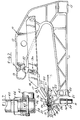
- the sheet bending apparatus embodying the invention comprises longitudinally spaced C-shaped frame members 10.
- Each frame member includes a lower arm 11 and an upper arm 12 which overlies the lower arm 11 in spaced relation thereto.
- a first fixed member 13 is fixed on the ends of the free lower arms 11 and defines a clamping surface 14.
- a longitudinally spaced base rail 15 is fixed to the rear end of the lower arms 11.
- a second bending member 16 is hinged to the first member 13, as presently described, to provide a means for bending the sheet material S.
- Clamping anvil member 17 extends longitudinally in overlying relationship to the clamping surface 14 of the first member 13.
- Means 18, 19, 19a are provided for moving the anvil member 17 toward and away from the clamping surface 14 to clamp the workpiece S on the clamping surface.
- These means include bars 18, a handle member 19 and a plurality of links 19a.
- the bars 18 are channel shaped and pivoted on each frame member 10 with the clamping member 17 fixed on the free ends thereof.
- the handle member 19 is pivoted to the upper arm 12 of each C-frame member 10 at 41 and connected to the pivot bars 18 by the plurality of links 19a which are extensible and pivoted at the upper end to the handle member 19 and at the lower end to the pivot bars 18.
- the first member 13 having the clamping surface 14 is formed as an aluminum extrusion and includes an upper tubular portion 20 and a lower U-shaped portion 21 including spaced flanges 22 engaging the free ends of lower arms 11.
- a plurality of longitudinally spaced projections 23 are provided as parts of the hinge to the second, bending member 16.
- Each projection 23 has a slot 24 formed therein and the slots 24 of the various projections 23 are in longitudinal alignment.
- Each slot 24 has its lower end spaced from the clamping surface 14 and extends outwardly and upwardly so that its upper end is generally near the plane of the clamping surface 14.
- Each slot 24 is preferably arcuate and preferably extends for substantially 90°, yet the center is spaced from the clamping surface 14.
- the second, bending member 16 is also in the form of an extrusion including a tubular portion 25 and a longitudinally extending leg 26 with a plurality of longitudinally spaced projections 27 having openings 28 therein.
- the projections 27 of the bending member 16 mesh with the projections 23 of the fixed member 13 and a pin 29 extends through the openings 28 and slots 24 to hinge the bending member 16 to the fixed member 13.
- the bending member 16 further includes a tooling portion 30 that extends upwardly and outwardly when the bending member 16 is initially in position for bending.
- a longitudinally extending plastic strip 31 is fixed in a generally L-shaped recess 32.
- the strip 31 includes a short leg 33 having an enlarged end portion 34 for engaging the recess 32.
- the other leg 35 of the strip 31 extends along the tooling portion 30 to define a sheet contacting portion.
- the strip 31 is preferably made of polyurethane.
- the fixed member 13 further includes a recess 36 extending longitudinally at the juncture of the clamping surface 14 and the projections 23.
- Recess 36 functions as a pocket into which any burrs may fall from a knife used for scoring the workpiece.
- the clamping surface 14 is spaced slightly above the projections 23 in order to minimize marring of the surface of the workpiece when it is inserted and removed.
- the bending member 16 also includes a recess 37 extending longitudinally between the projections 27 and the plastic strip or contacting portion 31.
- a workpiece of sheet material S is clamped against the clamping surface 14 by pivoting the handle member 19 and moving the oars 18 and the clamping anvil member 17 towards the first fixed member 13. Then the bending member 16 is moved by swinging the handle H upwardly so as to bring the contacting portion 31 of the bending member 16 in engagement with the sheet material S. As the bending member is swung upwardly, the hinge pin 29 on the bending member 16 moves along the slots 24 and is guided in a fashion such that the contacting portion 31 maintains substantially the same relative position of contact to the sheet material thereby minimizing marring of the surface of the sheet material.
- the arcuate slots 24 extend generally from below the nose or bending edge of the clamping anvil member 17 upwardly and outwardly toward the user so that the hinge pin 16 moves along the slots 24 as the workpiece is being bent from the position in Fig. 2 to the position in Fig. 4. Then the hinge pin 29 reaches the upper end of the slots 24, which end forms the fulcrum for the further movement of the bending member 16 (shown in phantom in Figure 4) to bend the workpiece into contact with the upper inclined surface of the clamping member 17.
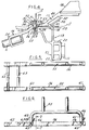
- the handle member 19 which is connected to the members 10 by pins 41 and to the links 19a by pins 42 is provided with recesses 43, 44 (Fig. 3) defined by integral portions 45, 46, 47 and 48, respectively, that are positioned so that the recesses 43, 44 lie substantially in the circle of the body of metal of the hollow handle member 19 thereby improving substantially the strength of the handle member.
- anvil or clamping member 17 is formed so that it has a tubular cross section including a heavy upper wall 49 and a lighter lower wall 50 generally parallel to the wall 49 and connected thereto by integral inclined portions 51, 52.
- the tubular portion extends rearwardly from the clamping portion 53. It has been found that such a construction contributes substantially to the strength of the sheet bending apparatus and the resultant ability to bend relatively thick sheet metal.
- a stabilizing assembly is added to the legs 55 which may be fixed or folded and attached to the members 13 and 15.
- the stabilizing assembly comprises spaced tubular transverse rails 56 which are preferably rectangular in cross section having openings 58, 59 for receiving the feet 60, 61 of the legs 55.
- Longitudinally extending hollow rails 62, 63 are fixed to extend lengthwise of the apparatus between the rails 56.
- the feet 60, 61 are preferably locked to the rails 56 by a pin 65 extending through the feet 60, 61 and the rails 56, 57.
- the pin 65 is retained by a clip 66 that is hinged to the head of the pin 65 and releasably connected to the free end of the pin 65 as shown in Fig. 7.
- a person utilizing the sheet bending apparatus inserts the sheet S and clamps it in position by manipulating the handle 19.
- the person further places one or both feet on one or both of the rails 62, 63 and simultaneously lifts the bending member 16 by means of one or more handles H.
- the length of the apparatus is on the order of 3 m (ten feet) or more and the sheet being bent is more, two persons of less stature may manipulate the apparatus by each person grasping a handle and placing one or both feet on the rails of the stabilizing assembly.
- a sheet bending apparatus embodying the invention is portable and yet permits bending of the sheet material which has a thickness substantially more than that heretofore thought possible.
Landscapes
- Engineering & Computer Science (AREA)
- Mechanical Engineering (AREA)
- Bending Of Plates, Rods, And Pipes (AREA)
- Folding Of Thin Sheet-Like Materials, Special Discharging Devices, And Others (AREA)
Applications Claiming Priority (3)
| Application Number | Priority Date | Filing Date | Title |
|---|---|---|---|
| US798207 | 1985-11-14 | ||
| US79820791A | 1991-11-26 | 1991-11-26 | |
| EP92119758A EP0544190B1 (de) | 1991-11-26 | 1992-11-20 | "Heavy duty" Blechabkantpresse |
Related Parent Applications (1)
| Application Number | Title | Priority Date | Filing Date |
|---|---|---|---|
| EP92119758.8 Division | 1992-11-20 |
Publications (3)
| Publication Number | Publication Date |
|---|---|
| EP0655286A2 true EP0655286A2 (de) | 1995-05-31 |
| EP0655286A3 EP0655286A3 (de) | 1995-07-12 |
| EP0655286B1 EP0655286B1 (de) | 1997-05-14 |
Family
ID=25172801
Family Applications (2)
| Application Number | Title | Priority Date | Filing Date |
|---|---|---|---|
| EP95100938A Expired - Lifetime EP0655286B1 (de) | 1991-11-26 | 1992-11-20 | Tragbare Blechbiegevorrichtung |
| EP92119758A Expired - Lifetime EP0544190B1 (de) | 1991-11-26 | 1992-11-20 | "Heavy duty" Blechabkantpresse |
Family Applications After (1)
| Application Number | Title | Priority Date | Filing Date |
|---|---|---|---|
| EP92119758A Expired - Lifetime EP0544190B1 (de) | 1991-11-26 | 1992-11-20 | "Heavy duty" Blechabkantpresse |
Country Status (5)
| Country | Link |
|---|---|
| US (2) | US5343728A (de) |
| EP (2) | EP0655286B1 (de) |
| CA (1) | CA2082759A1 (de) |
| DE (2) | DE69219790T2 (de) |
| ES (2) | ES2105786T3 (de) |
Families Citing this family (13)
| Publication number | Priority date | Publication date | Assignee | Title |
|---|---|---|---|---|
| DE4335543A1 (de) * | 1993-10-19 | 1995-04-20 | Unimet Gmbh | Verfahren und Vorrichtung zum Biegen eines dünnwandigen Werkstückes |
| DE19901794A1 (de) * | 1999-01-19 | 2000-07-27 | Reinhardt Gmbh Maschbau | Biegemaschine |
| US6571594B2 (en) | 2001-11-02 | 2003-06-03 | Tapco International, Inc. | Open back brake |
| US6619101B1 (en) * | 2002-04-19 | 2003-09-16 | Fci Americas Technology, Inc. | Crimping tool head with reinforcing beams for optimizing weight |
| US6907820B2 (en) * | 2003-03-20 | 2005-06-21 | Mitek Holdings, Inc. | Press for assembling structures |
| US7191631B2 (en) * | 2003-11-14 | 2007-03-20 | Tapco International Corporation | Sheet metal bending brake with improved hinge |
| US20070277577A1 (en) * | 2004-10-29 | 2007-12-06 | Allen Clyde G | Sheet metal brake and hinge mechanism therefor |
| US7500375B2 (en) * | 2005-02-24 | 2009-03-10 | Van Mark Products | Apparatus for forming a gutter cap |
| US20080223102A1 (en) * | 2007-03-16 | 2008-09-18 | Alum-A-Pole Corporation | Spring clamp for a support leg |
| JP5382231B2 (ja) * | 2010-12-22 | 2014-01-08 | トヨタ自動車株式会社 | 機械プレス用金型 |
| US8371541B2 (en) | 2011-03-28 | 2013-02-12 | Van Mark Products Corporation | Portable tool stand |
| CA2814923C (en) | 2013-02-11 | 2016-10-11 | Alexandre Cloutier | Gauge kits for sheet bending brakes |
| KR20200078596A (ko) * | 2017-10-29 | 2020-07-01 | 챠이나 게엠베하 | 폴딩 플라이어 |
Family Cites Families (20)
| Publication number | Priority date | Publication date | Assignee | Title |
|---|---|---|---|---|
| US131239A (en) * | 1872-09-10 | Improvement in machines for making metallic moldings | ||
| US934701A (en) * | 1908-09-05 | 1909-09-21 | John M Swanson | Mechanical hammer. |
| US2181566A (en) * | 1936-06-29 | 1939-11-28 | Whitney Metal Tool Company | Portable bending brake |
| US2343441A (en) * | 1941-10-21 | 1944-03-07 | Nat Supply Co | Bending brake |
| US2434028A (en) * | 1945-03-29 | 1948-01-06 | Wieland Roy | Machine for bending edges of sheet metal plates |
| CH403677A (de) * | 1963-06-21 | 1965-11-30 | Pirchegger Erwin | Zusammenlegbarer Unterstellbock |
| FR1394222A (fr) * | 1964-02-12 | 1965-04-02 | Bâti de machines à coudre industrielles | |
| US3481174A (en) * | 1967-06-19 | 1969-12-02 | Henry C Barnack | Sheet metal brake |
| GB1267032A (de) * | 1968-03-04 | 1972-03-15 | ||
| US3482427A (en) * | 1968-05-06 | 1969-12-09 | Henry C Barnack | Sheet metal brake |
| DE2610774C3 (de) * | 1976-03-15 | 1978-11-09 | Baumgarten, Kg, Stanz-, Zieh- Und Presswerk, 5244 Daaden | Abkant- bzw. Biegebank für Bleche o.dgl |
| US4372142A (en) * | 1980-11-28 | 1983-02-08 | Tapco Products Company, Inc. | Sheet bending brake |
| US4494397A (en) * | 1982-03-18 | 1985-01-22 | Tapco Products Company, Inc. | Portable sheet bending brake |
| FR2523829B1 (fr) * | 1982-03-29 | 1986-03-14 | Durand Daniel | Ensemble transformable pouvant etre utilise a volonte comme table, etabli ou echafaudage |
| US4512174A (en) * | 1982-06-07 | 1985-04-23 | Tapco Products Company, Inc. | Combined sheet bending brake and platform |
| US4557132A (en) * | 1984-02-03 | 1985-12-10 | Tapco Products Company, Inc. | Sheet bending brake |
| DE3536733A1 (de) * | 1985-10-15 | 1987-04-23 | Alutec Aluminium System Gmbh | Vorrichtung zur ausfuehrung von arbeitsvorgaengen, insbesondere fuer die serienfertigung |
| US4713957A (en) * | 1986-08-12 | 1987-12-22 | Eder Ernest J | Reverse bend attachment for a sheet metal brake |
| GB8714073D0 (en) * | 1987-06-16 | 1987-07-22 | Rutherford W S | Pipe bender |
| DE9200185U1 (de) * | 1992-01-09 | 1992-03-26 | Schmitz, Sigrid, 4150 Krefeld | Mobilwerkband |
-
1992
- 1992-11-12 CA CA002082759A patent/CA2082759A1/en not_active Abandoned
- 1992-11-20 DE DE69219790T patent/DE69219790T2/de not_active Expired - Fee Related
- 1992-11-20 EP EP95100938A patent/EP0655286B1/de not_active Expired - Lifetime
- 1992-11-20 ES ES95100938T patent/ES2105786T3/es not_active Expired - Lifetime
- 1992-11-20 DE DE69204027T patent/DE69204027T2/de not_active Expired - Fee Related
- 1992-11-20 ES ES92119758T patent/ES2075995T3/es not_active Expired - Lifetime
- 1992-11-20 EP EP92119758A patent/EP0544190B1/de not_active Expired - Lifetime
- 1992-12-07 US US07/987,249 patent/US5343728A/en not_active Expired - Lifetime
-
1994
- 1994-06-30 US US08/268,808 patent/US5582055A/en not_active Expired - Lifetime
Also Published As
| Publication number | Publication date |
|---|---|
| CA2082759A1 (en) | 1993-05-27 |
| US5343728A (en) | 1994-09-06 |
| EP0544190B1 (de) | 1995-08-09 |
| DE69219790D1 (de) | 1997-06-19 |
| EP0655286B1 (de) | 1997-05-14 |
| ES2075995T3 (es) | 1995-10-16 |
| EP0544190A1 (de) | 1993-06-02 |
| DE69204027D1 (de) | 1995-09-14 |
| ES2105786T3 (es) | 1997-10-16 |
| US5582055A (en) | 1996-12-10 |
| EP0655286A3 (de) | 1995-07-12 |
| DE69204027T2 (de) | 1996-04-04 |
| DE69219790T2 (de) | 1998-01-22 |
Similar Documents
| Publication | Publication Date | Title |
|---|---|---|
| US6389864B1 (en) | Heavy duty sheet bending brake | |
| US4557132A (en) | Sheet bending brake | |
| EP0655286A2 (de) | Tragbare Blechbiegevorrichtung | |
| US5706693A (en) | Combined sheet bending brake and cutter | |
| US5899132A (en) | Tilting saw table | |
| US20070022859A1 (en) | High mechanical advantage punch | |
| EP3156191A1 (de) | Sägebock | |
| US3481174A (en) | Sheet metal brake | |
| US4321817A (en) | Sheet bending brake | |
| US5992203A (en) | Coil holder for a sheet bending brake | |
| US4364254A (en) | Combined sheet bending brake, table and coil support | |
| EP1958737A1 (de) | Tragbare Werkbank | |
| US4445356A (en) | Combined portable sheet bending brake and coil holder | |
| JPH06508068A (ja) | クランプ装置 | |
| EP0098101A2 (de) | Schraubstock und Werkbänke | |
| US5761939A (en) | Automatic indexer for a sheet bending brake | |
| US4592518A (en) | Coil holder | |
| US4512174A (en) | Combined sheet bending brake and platform | |
| US5505069A (en) | Sheet bending brake | |
| US6003357A (en) | Sheet metal brake accessory | |
| US6526857B1 (en) | Surface mounted ergonomic cutter | |
| US6901783B2 (en) | Device having pivotable wheel mechanism | |
| US6802198B2 (en) | Open back brake | |
| US6763695B1 (en) | Sheet material cutter and cut-off gauge for use in combination with a sheet bending brake | |
| RU235488U1 (ru) | Листогибочный станок |
Legal Events
| Date | Code | Title | Description |
|---|---|---|---|
| PUAI | Public reference made under article 153(3) epc to a published international application that has entered the european phase |
Free format text: ORIGINAL CODE: 0009012 |
|
| PUAL | Search report despatched |
Free format text: ORIGINAL CODE: 0009013 |
|
| AC | Divisional application: reference to earlier application |
Ref document number: 544190 Country of ref document: EP |
|
| AK | Designated contracting states |
Kind code of ref document: A2 Designated state(s): DE ES FR GB IT |
|
| AK | Designated contracting states |
Kind code of ref document: A3 Designated state(s): DE ES FR GB IT |
|
| 17P | Request for examination filed |
Effective date: 19950826 |
|
| GRAG | Despatch of communication of intention to grant |
Free format text: ORIGINAL CODE: EPIDOS AGRA |
|
| GRAH | Despatch of communication of intention to grant a patent |
Free format text: ORIGINAL CODE: EPIDOS IGRA |
|
| 17Q | First examination report despatched |
Effective date: 19961004 |
|
| GRAH | Despatch of communication of intention to grant a patent |
Free format text: ORIGINAL CODE: EPIDOS IGRA |
|
| ITF | It: translation for a ep patent filed | ||
| GRAA | (expected) grant |
Free format text: ORIGINAL CODE: 0009210 |
|
| AC | Divisional application: reference to earlier application |
Ref document number: 544190 Country of ref document: EP |
|
| AK | Designated contracting states |
Kind code of ref document: B1 Designated state(s): DE ES FR GB IT |
|
| REF | Corresponds to: |
Ref document number: 69219790 Country of ref document: DE Date of ref document: 19970619 |
|
| ET | Fr: translation filed | ||
| REG | Reference to a national code |
Ref country code: ES Ref legal event code: FG2A Ref document number: 2105786 Country of ref document: ES Kind code of ref document: T3 |
|
| PLBE | No opposition filed within time limit |
Free format text: ORIGINAL CODE: 0009261 |
|
| STAA | Information on the status of an ep patent application or granted ep patent |
Free format text: STATUS: NO OPPOSITION FILED WITHIN TIME LIMIT |
|
| 26N | No opposition filed | ||
| PGFP | Annual fee paid to national office [announced via postgrant information from national office to epo] |
Ref country code: FR Payment date: 19981030 Year of fee payment: 7 |
|
| PGFP | Annual fee paid to national office [announced via postgrant information from national office to epo] |
Ref country code: GB Payment date: 19981102 Year of fee payment: 7 |
|
| PGFP | Annual fee paid to national office [announced via postgrant information from national office to epo] |
Ref country code: DE Payment date: 19981103 Year of fee payment: 7 |
|
| PGFP | Annual fee paid to national office [announced via postgrant information from national office to epo] |
Ref country code: ES Payment date: 19981120 Year of fee payment: 7 |
|
| PG25 | Lapsed in a contracting state [announced via postgrant information from national office to epo] |
Ref country code: GB Free format text: LAPSE BECAUSE OF NON-PAYMENT OF DUE FEES Effective date: 19991120 |
|
| PG25 | Lapsed in a contracting state [announced via postgrant information from national office to epo] |
Ref country code: ES Free format text: LAPSE BECAUSE OF NON-PAYMENT OF DUE FEES Effective date: 19991121 |
|
| GBPC | Gb: european patent ceased through non-payment of renewal fee |
Effective date: 19991120 |
|
| PG25 | Lapsed in a contracting state [announced via postgrant information from national office to epo] |
Ref country code: FR Free format text: LAPSE BECAUSE OF NON-PAYMENT OF DUE FEES Effective date: 20000731 |
|
| PG25 | Lapsed in a contracting state [announced via postgrant information from national office to epo] |
Ref country code: DE Free format text: LAPSE BECAUSE OF NON-PAYMENT OF DUE FEES Effective date: 20000901 |
|
| REG | Reference to a national code |
Ref country code: FR Ref legal event code: ST |
|
| REG | Reference to a national code |
Ref country code: ES Ref legal event code: FD2A Effective date: 20001214 |
|
| PG25 | Lapsed in a contracting state [announced via postgrant information from national office to epo] |
Ref country code: IT Free format text: LAPSE BECAUSE OF NON-PAYMENT OF DUE FEES;WARNING: LAPSES OF ITALIAN PATENTS WITH EFFECTIVE DATE BEFORE 2007 MAY HAVE OCCURRED AT ANY TIME BEFORE 2007. THE CORRECT EFFECTIVE DATE MAY BE DIFFERENT FROM THE ONE RECORDED. Effective date: 20051120 |