EP0655314B1 - Utilisation multiple d'air de travail - Google Patents
Utilisation multiple d'air de travail Download PDFInfo
- Publication number
- EP0655314B1 EP0655314B1 EP94118335A EP94118335A EP0655314B1 EP 0655314 B1 EP0655314 B1 EP 0655314B1 EP 94118335 A EP94118335 A EP 94118335A EP 94118335 A EP94118335 A EP 94118335A EP 0655314 B1 EP0655314 B1 EP 0655314B1
- Authority
- EP
- European Patent Office
- Prior art keywords
- operating air
- supply
- air
- pneumatic
- structural element
- Prior art date
- Legal status (The legal status is an assumption and is not a legal conclusion. Google has not performed a legal analysis and makes no representation as to the accuracy of the status listed.)
- Expired - Lifetime
Links
- 238000000034 method Methods 0.000 claims description 30
- 238000012546 transfer Methods 0.000 claims description 28
- 238000007664 blowing Methods 0.000 claims description 25
- 230000008569 process Effects 0.000 claims description 21
- 238000003860 storage Methods 0.000 claims description 10
- 230000008878 coupling Effects 0.000 claims description 7
- 238000010168 coupling process Methods 0.000 claims description 7
- 238000005859 coupling reaction Methods 0.000 claims description 7
- 238000013022 venting Methods 0.000 claims description 7
- 229920001169 thermoplastic Polymers 0.000 claims description 6
- 230000005484 gravity Effects 0.000 claims description 4
- 238000000465 moulding Methods 0.000 claims description 4
- 239000004416 thermosoftening plastic Substances 0.000 claims description 4
- 238000005496 tempering Methods 0.000 claims description 3
- 229920002994 synthetic fiber Polymers 0.000 claims 2
- 230000007704 transition Effects 0.000 description 10
- 238000000071 blow moulding Methods 0.000 description 6
- 230000009467 reduction Effects 0.000 description 6
- 238000009423 ventilation Methods 0.000 description 6
- 238000004519 manufacturing process Methods 0.000 description 5
- 238000010586 diagram Methods 0.000 description 3
- 239000000463 material Substances 0.000 description 3
- 229920000139 polyethylene terephthalate Polymers 0.000 description 3
- 239000005020 polyethylene terephthalate Substances 0.000 description 3
- 230000003584 silencer Effects 0.000 description 3
- 230000004913 activation Effects 0.000 description 2
- -1 polyethylene terephthalate Polymers 0.000 description 2
- 238000007493 shaping process Methods 0.000 description 2
- 230000015572 biosynthetic process Effects 0.000 description 1
- 230000008859 change Effects 0.000 description 1
- 230000006835 compression Effects 0.000 description 1
- 238000007906 compression Methods 0.000 description 1
- 238000010276 construction Methods 0.000 description 1
- 230000001419 dependent effect Effects 0.000 description 1
- 238000013461 design Methods 0.000 description 1
- 238000011161 development Methods 0.000 description 1
- 230000000694 effects Effects 0.000 description 1
- 238000010438 heat treatment Methods 0.000 description 1
- 238000002347 injection Methods 0.000 description 1
- 239000007924 injection Substances 0.000 description 1
- 238000001746 injection moulding Methods 0.000 description 1
- 238000012432 intermediate storage Methods 0.000 description 1
- 230000007257 malfunction Effects 0.000 description 1
- 238000012544 monitoring process Methods 0.000 description 1
- 239000004033 plastic Substances 0.000 description 1
- 229920003023 plastic Polymers 0.000 description 1
- 238000010079 rubber tapping Methods 0.000 description 1
- 238000007789 sealing Methods 0.000 description 1
- 238000003856 thermoforming Methods 0.000 description 1
Images


Classifications
-
- B—PERFORMING OPERATIONS; TRANSPORTING
- B29—WORKING OF PLASTICS; WORKING OF SUBSTANCES IN A PLASTIC STATE IN GENERAL
- B29C—SHAPING OR JOINING OF PLASTICS; SHAPING OF MATERIAL IN A PLASTIC STATE, NOT OTHERWISE PROVIDED FOR; AFTER-TREATMENT OF THE SHAPED PRODUCTS, e.g. REPAIRING
- B29C49/00—Blow-moulding, i.e. blowing a preform or parison to a desired shape within a mould; Apparatus therefor
- B29C49/42—Component parts, details or accessories; Auxiliary operations
- B29C49/78—Measuring, controlling or regulating
- B29C49/783—Measuring, controlling or regulating blowing pressure
-
- B—PERFORMING OPERATIONS; TRANSPORTING
- B29—WORKING OF PLASTICS; WORKING OF SUBSTANCES IN A PLASTIC STATE IN GENERAL
- B29C—SHAPING OR JOINING OF PLASTICS; SHAPING OF MATERIAL IN A PLASTIC STATE, NOT OTHERWISE PROVIDED FOR; AFTER-TREATMENT OF THE SHAPED PRODUCTS, e.g. REPAIRING
- B29C49/00—Blow-moulding, i.e. blowing a preform or parison to a desired shape within a mould; Apparatus therefor
- B29C49/08—Biaxial stretching during blow-moulding
- B29C49/10—Biaxial stretching during blow-moulding using mechanical means for prestretching
- B29C49/12—Stretching rods
-
- B—PERFORMING OPERATIONS; TRANSPORTING
- B29—WORKING OF PLASTICS; WORKING OF SUBSTANCES IN A PLASTIC STATE IN GENERAL
- B29C—SHAPING OR JOINING OF PLASTICS; SHAPING OF MATERIAL IN A PLASTIC STATE, NOT OTHERWISE PROVIDED FOR; AFTER-TREATMENT OF THE SHAPED PRODUCTS, e.g. REPAIRING
- B29C49/00—Blow-moulding, i.e. blowing a preform or parison to a desired shape within a mould; Apparatus therefor
- B29C49/42—Component parts, details or accessories; Auxiliary operations
- B29C49/42414—Treatment of preforms, e.g. cleaning or spraying water for improved heat transfer
-
- B—PERFORMING OPERATIONS; TRANSPORTING
- B29—WORKING OF PLASTICS; WORKING OF SUBSTANCES IN A PLASTIC STATE IN GENERAL
- B29C—SHAPING OR JOINING OF PLASTICS; SHAPING OF MATERIAL IN A PLASTIC STATE, NOT OTHERWISE PROVIDED FOR; AFTER-TREATMENT OF THE SHAPED PRODUCTS, e.g. REPAIRING
- B29C49/00—Blow-moulding, i.e. blowing a preform or parison to a desired shape within a mould; Apparatus therefor
- B29C49/42—Component parts, details or accessories; Auxiliary operations
- B29C49/4284—Means for recycling or reusing auxiliaries or materials, e.g. blowing fluids or energy
- B29C49/42845—Recycling or reusing of fluid, e.g. pressure
- B29C49/42855—Blowing fluids, e.g. reducing fluid consumption
-
- B—PERFORMING OPERATIONS; TRANSPORTING
- B29—WORKING OF PLASTICS; WORKING OF SUBSTANCES IN A PLASTIC STATE IN GENERAL
- B29C—SHAPING OR JOINING OF PLASTICS; SHAPING OF MATERIAL IN A PLASTIC STATE, NOT OTHERWISE PROVIDED FOR; AFTER-TREATMENT OF THE SHAPED PRODUCTS, e.g. REPAIRING
- B29C49/00—Blow-moulding, i.e. blowing a preform or parison to a desired shape within a mould; Apparatus therefor
- B29C49/42—Component parts, details or accessories; Auxiliary operations
- B29C49/56—Opening, closing or clamping means
- B29C49/5606—Pneumatically operated, i.e. closing or opening of the mould parts is done by hydraulic means
-
- F—MECHANICAL ENGINEERING; LIGHTING; HEATING; WEAPONS; BLASTING
- F15—FLUID-PRESSURE ACTUATORS; HYDRAULICS OR PNEUMATICS IN GENERAL
- F15B—SYSTEMS ACTING BY MEANS OF FLUIDS IN GENERAL; FLUID-PRESSURE ACTUATORS, e.g. SERVOMOTORS; DETAILS OF FLUID-PRESSURE SYSTEMS, NOT OTHERWISE PROVIDED FOR
- F15B11/00—Servomotor systems without provision for follow-up action; Circuits therefor
- F15B11/06—Servomotor systems without provision for follow-up action; Circuits therefor involving features specific to the use of a compressible medium, e.g. air, steam
- F15B11/064—Servomotor systems without provision for follow-up action; Circuits therefor involving features specific to the use of a compressible medium, e.g. air, steam with devices for saving the compressible medium
-
- B—PERFORMING OPERATIONS; TRANSPORTING
- B29—WORKING OF PLASTICS; WORKING OF SUBSTANCES IN A PLASTIC STATE IN GENERAL
- B29C—SHAPING OR JOINING OF PLASTICS; SHAPING OF MATERIAL IN A PLASTIC STATE, NOT OTHERWISE PROVIDED FOR; AFTER-TREATMENT OF THE SHAPED PRODUCTS, e.g. REPAIRING
- B29C49/00—Blow-moulding, i.e. blowing a preform or parison to a desired shape within a mould; Apparatus therefor
- B29C49/42—Component parts, details or accessories; Auxiliary operations
- B29C49/56—Opening, closing or clamping means
- B29C2049/566—Locking means
- B29C2049/5666—Pneumatic
-
- B—PERFORMING OPERATIONS; TRANSPORTING
- B29—WORKING OF PLASTICS; WORKING OF SUBSTANCES IN A PLASTIC STATE IN GENERAL
- B29C—SHAPING OR JOINING OF PLASTICS; SHAPING OF MATERIAL IN A PLASTIC STATE, NOT OTHERWISE PROVIDED FOR; AFTER-TREATMENT OF THE SHAPED PRODUCTS, e.g. REPAIRING
- B29C49/00—Blow-moulding, i.e. blowing a preform or parison to a desired shape within a mould; Apparatus therefor
- B29C49/42—Component parts, details or accessories; Auxiliary operations
- B29C49/58—Blowing means
- B29C2049/5806—Means for fixing the blowing means with the mould
- B29C2049/581—Mechanical, e.g. fingers or toothed wheels
-
- B—PERFORMING OPERATIONS; TRANSPORTING
- B29—WORKING OF PLASTICS; WORKING OF SUBSTANCES IN A PLASTIC STATE IN GENERAL
- B29C—SHAPING OR JOINING OF PLASTICS; SHAPING OF MATERIAL IN A PLASTIC STATE, NOT OTHERWISE PROVIDED FOR; AFTER-TREATMENT OF THE SHAPED PRODUCTS, e.g. REPAIRING
- B29C49/00—Blow-moulding, i.e. blowing a preform or parison to a desired shape within a mould; Apparatus therefor
- B29C49/42—Component parts, details or accessories; Auxiliary operations
- B29C49/78—Measuring, controlling or regulating
- B29C49/783—Measuring, controlling or regulating blowing pressure
- B29C2049/7832—Blowing with two or more pressure levels
-
- B—PERFORMING OPERATIONS; TRANSPORTING
- B29—WORKING OF PLASTICS; WORKING OF SUBSTANCES IN A PLASTIC STATE IN GENERAL
- B29C—SHAPING OR JOINING OF PLASTICS; SHAPING OF MATERIAL IN A PLASTIC STATE, NOT OTHERWISE PROVIDED FOR; AFTER-TREATMENT OF THE SHAPED PRODUCTS, e.g. REPAIRING
- B29C49/00—Blow-moulding, i.e. blowing a preform or parison to a desired shape within a mould; Apparatus therefor
- B29C49/42—Component parts, details or accessories; Auxiliary operations
- B29C49/78—Measuring, controlling or regulating
- B29C2049/788—Controller type or interface
- B29C2049/7881—Mechanical control
-
- B—PERFORMING OPERATIONS; TRANSPORTING
- B29—WORKING OF PLASTICS; WORKING OF SUBSTANCES IN A PLASTIC STATE IN GENERAL
- B29C—SHAPING OR JOINING OF PLASTICS; SHAPING OF MATERIAL IN A PLASTIC STATE, NOT OTHERWISE PROVIDED FOR; AFTER-TREATMENT OF THE SHAPED PRODUCTS, e.g. REPAIRING
- B29C2949/00—Indexing scheme relating to blow-moulding
- B29C2949/07—Preforms or parisons characterised by their configuration
- B29C2949/0715—Preforms or parisons characterised by their configuration the preform having one end closed
-
- B—PERFORMING OPERATIONS; TRANSPORTING
- B29—WORKING OF PLASTICS; WORKING OF SUBSTANCES IN A PLASTIC STATE IN GENERAL
- B29C—SHAPING OR JOINING OF PLASTICS; SHAPING OF MATERIAL IN A PLASTIC STATE, NOT OTHERWISE PROVIDED FOR; AFTER-TREATMENT OF THE SHAPED PRODUCTS, e.g. REPAIRING
- B29C49/00—Blow-moulding, i.e. blowing a preform or parison to a desired shape within a mould; Apparatus therefor
- B29C49/02—Combined blow-moulding and manufacture of the preform or the parison
- B29C49/06—Injection blow-moulding
-
- B—PERFORMING OPERATIONS; TRANSPORTING
- B29—WORKING OF PLASTICS; WORKING OF SUBSTANCES IN A PLASTIC STATE IN GENERAL
- B29C—SHAPING OR JOINING OF PLASTICS; SHAPING OF MATERIAL IN A PLASTIC STATE, NOT OTHERWISE PROVIDED FOR; AFTER-TREATMENT OF THE SHAPED PRODUCTS, e.g. REPAIRING
- B29C49/00—Blow-moulding, i.e. blowing a preform or parison to a desired shape within a mould; Apparatus therefor
- B29C49/08—Biaxial stretching during blow-moulding
- B29C49/10—Biaxial stretching during blow-moulding using mechanical means for prestretching
- B29C49/122—Drive means therefor
- B29C49/1222—Pneumatic
-
- B—PERFORMING OPERATIONS; TRANSPORTING
- B29—WORKING OF PLASTICS; WORKING OF SUBSTANCES IN A PLASTIC STATE IN GENERAL
- B29C—SHAPING OR JOINING OF PLASTICS; SHAPING OF MATERIAL IN A PLASTIC STATE, NOT OTHERWISE PROVIDED FOR; AFTER-TREATMENT OF THE SHAPED PRODUCTS, e.g. REPAIRING
- B29C49/00—Blow-moulding, i.e. blowing a preform or parison to a desired shape within a mould; Apparatus therefor
- B29C49/08—Biaxial stretching during blow-moulding
- B29C49/10—Biaxial stretching during blow-moulding using mechanical means for prestretching
- B29C49/122—Drive means therefor
- B29C49/1229—Drive means therefor being a cam mechanism
-
- B—PERFORMING OPERATIONS; TRANSPORTING
- B29—WORKING OF PLASTICS; WORKING OF SUBSTANCES IN A PLASTIC STATE IN GENERAL
- B29C—SHAPING OR JOINING OF PLASTICS; SHAPING OF MATERIAL IN A PLASTIC STATE, NOT OTHERWISE PROVIDED FOR; AFTER-TREATMENT OF THE SHAPED PRODUCTS, e.g. REPAIRING
- B29C49/00—Blow-moulding, i.e. blowing a preform or parison to a desired shape within a mould; Apparatus therefor
- B29C49/42—Component parts, details or accessories; Auxiliary operations
- B29C49/4205—Handling means, e.g. transfer, loading or discharging means
- B29C49/42073—Grippers
- B29C49/42075—Grippers with pivoting clamps
-
- B—PERFORMING OPERATIONS; TRANSPORTING
- B29—WORKING OF PLASTICS; WORKING OF SUBSTANCES IN A PLASTIC STATE IN GENERAL
- B29C—SHAPING OR JOINING OF PLASTICS; SHAPING OF MATERIAL IN A PLASTIC STATE, NOT OTHERWISE PROVIDED FOR; AFTER-TREATMENT OF THE SHAPED PRODUCTS, e.g. REPAIRING
- B29C49/00—Blow-moulding, i.e. blowing a preform or parison to a desired shape within a mould; Apparatus therefor
- B29C49/42—Component parts, details or accessories; Auxiliary operations
- B29C49/4205—Handling means, e.g. transfer, loading or discharging means
- B29C49/42073—Grippers
- B29C49/42085—Grippers holding inside the neck
-
- B—PERFORMING OPERATIONS; TRANSPORTING
- B29—WORKING OF PLASTICS; WORKING OF SUBSTANCES IN A PLASTIC STATE IN GENERAL
- B29K—INDEXING SCHEME ASSOCIATED WITH SUBCLASSES B29B, B29C OR B29D, RELATING TO MOULDING MATERIALS OR TO MATERIALS FOR MOULDS, REINFORCEMENTS, FILLERS OR PREFORMED PARTS, e.g. INSERTS
- B29K2067/00—Use of polyesters or derivatives thereof, as moulding material
-
- F—MECHANICAL ENGINEERING; LIGHTING; HEATING; WEAPONS; BLASTING
- F15—FLUID-PRESSURE ACTUATORS; HYDRAULICS OR PNEUMATICS IN GENERAL
- F15B—SYSTEMS ACTING BY MEANS OF FLUIDS IN GENERAL; FLUID-PRESSURE ACTUATORS, e.g. SERVOMOTORS; DETAILS OF FLUID-PRESSURE SYSTEMS, NOT OTHERWISE PROVIDED FOR
- F15B2211/00—Circuits for servomotor systems
- F15B2211/20—Fluid pressure source, e.g. accumulator or variable axial piston pump
- F15B2211/205—Systems with pumps
- F15B2211/20576—Systems with pumps with multiple pumps
-
- F—MECHANICAL ENGINEERING; LIGHTING; HEATING; WEAPONS; BLASTING
- F15—FLUID-PRESSURE ACTUATORS; HYDRAULICS OR PNEUMATICS IN GENERAL
- F15B—SYSTEMS ACTING BY MEANS OF FLUIDS IN GENERAL; FLUID-PRESSURE ACTUATORS, e.g. SERVOMOTORS; DETAILS OF FLUID-PRESSURE SYSTEMS, NOT OTHERWISE PROVIDED FOR
- F15B2211/00—Circuits for servomotor systems
- F15B2211/20—Fluid pressure source, e.g. accumulator or variable axial piston pump
- F15B2211/21—Systems with pressure sources other than pumps, e.g. with a pyrotechnical charge
- F15B2211/212—Systems with pressure sources other than pumps, e.g. with a pyrotechnical charge the pressure sources being accumulators
-
- F—MECHANICAL ENGINEERING; LIGHTING; HEATING; WEAPONS; BLASTING
- F15—FLUID-PRESSURE ACTUATORS; HYDRAULICS OR PNEUMATICS IN GENERAL
- F15B—SYSTEMS ACTING BY MEANS OF FLUIDS IN GENERAL; FLUID-PRESSURE ACTUATORS, e.g. SERVOMOTORS; DETAILS OF FLUID-PRESSURE SYSTEMS, NOT OTHERWISE PROVIDED FOR
- F15B2211/00—Circuits for servomotor systems
- F15B2211/40—Flow control
- F15B2211/405—Flow control characterised by the type of flow control means or valve
- F15B2211/40515—Flow control characterised by the type of flow control means or valve with variable throttles or orifices
-
- F—MECHANICAL ENGINEERING; LIGHTING; HEATING; WEAPONS; BLASTING
- F15—FLUID-PRESSURE ACTUATORS; HYDRAULICS OR PNEUMATICS IN GENERAL
- F15B—SYSTEMS ACTING BY MEANS OF FLUIDS IN GENERAL; FLUID-PRESSURE ACTUATORS, e.g. SERVOMOTORS; DETAILS OF FLUID-PRESSURE SYSTEMS, NOT OTHERWISE PROVIDED FOR
- F15B2211/00—Circuits for servomotor systems
- F15B2211/40—Flow control
- F15B2211/415—Flow control characterised by the connections of the flow control means in the circuit
- F15B2211/41509—Flow control characterised by the connections of the flow control means in the circuit being connected to a pressure source and a directional control valve
- F15B2211/41518—Flow control characterised by the connections of the flow control means in the circuit being connected to a pressure source and a directional control valve being connected to multiple pressure sources
-
- F—MECHANICAL ENGINEERING; LIGHTING; HEATING; WEAPONS; BLASTING
- F15—FLUID-PRESSURE ACTUATORS; HYDRAULICS OR PNEUMATICS IN GENERAL
- F15B—SYSTEMS ACTING BY MEANS OF FLUIDS IN GENERAL; FLUID-PRESSURE ACTUATORS, e.g. SERVOMOTORS; DETAILS OF FLUID-PRESSURE SYSTEMS, NOT OTHERWISE PROVIDED FOR
- F15B2211/00—Circuits for servomotor systems
- F15B2211/40—Flow control
- F15B2211/415—Flow control characterised by the connections of the flow control means in the circuit
- F15B2211/41527—Flow control characterised by the connections of the flow control means in the circuit being connected to an output member and a directional control valve
-
- F—MECHANICAL ENGINEERING; LIGHTING; HEATING; WEAPONS; BLASTING
- F15—FLUID-PRESSURE ACTUATORS; HYDRAULICS OR PNEUMATICS IN GENERAL
- F15B—SYSTEMS ACTING BY MEANS OF FLUIDS IN GENERAL; FLUID-PRESSURE ACTUATORS, e.g. SERVOMOTORS; DETAILS OF FLUID-PRESSURE SYSTEMS, NOT OTHERWISE PROVIDED FOR
- F15B2211/00—Circuits for servomotor systems
- F15B2211/40—Flow control
- F15B2211/45—Control of bleed-off flow, e.g. control of bypass flow to the return line
-
- F—MECHANICAL ENGINEERING; LIGHTING; HEATING; WEAPONS; BLASTING
- F15—FLUID-PRESSURE ACTUATORS; HYDRAULICS OR PNEUMATICS IN GENERAL
- F15B—SYSTEMS ACTING BY MEANS OF FLUIDS IN GENERAL; FLUID-PRESSURE ACTUATORS, e.g. SERVOMOTORS; DETAILS OF FLUID-PRESSURE SYSTEMS, NOT OTHERWISE PROVIDED FOR
- F15B2211/00—Circuits for servomotor systems
- F15B2211/40—Flow control
- F15B2211/455—Control of flow in the feed line, i.e. meter-in control
-
- F—MECHANICAL ENGINEERING; LIGHTING; HEATING; WEAPONS; BLASTING
- F15—FLUID-PRESSURE ACTUATORS; HYDRAULICS OR PNEUMATICS IN GENERAL
- F15B—SYSTEMS ACTING BY MEANS OF FLUIDS IN GENERAL; FLUID-PRESSURE ACTUATORS, e.g. SERVOMOTORS; DETAILS OF FLUID-PRESSURE SYSTEMS, NOT OTHERWISE PROVIDED FOR
- F15B2211/00—Circuits for servomotor systems
- F15B2211/40—Flow control
- F15B2211/46—Control of flow in the return line, i.e. meter-out control
-
- F—MECHANICAL ENGINEERING; LIGHTING; HEATING; WEAPONS; BLASTING
- F15—FLUID-PRESSURE ACTUATORS; HYDRAULICS OR PNEUMATICS IN GENERAL
- F15B—SYSTEMS ACTING BY MEANS OF FLUIDS IN GENERAL; FLUID-PRESSURE ACTUATORS, e.g. SERVOMOTORS; DETAILS OF FLUID-PRESSURE SYSTEMS, NOT OTHERWISE PROVIDED FOR
- F15B2211/00—Circuits for servomotor systems
- F15B2211/50—Pressure control
- F15B2211/505—Pressure control characterised by the type of pressure control means
- F15B2211/50509—Pressure control characterised by the type of pressure control means the pressure control means controlling a pressure upstream of the pressure control means
- F15B2211/50518—Pressure control characterised by the type of pressure control means the pressure control means controlling a pressure upstream of the pressure control means using pressure relief valves
-
- F—MECHANICAL ENGINEERING; LIGHTING; HEATING; WEAPONS; BLASTING
- F15—FLUID-PRESSURE ACTUATORS; HYDRAULICS OR PNEUMATICS IN GENERAL
- F15B—SYSTEMS ACTING BY MEANS OF FLUIDS IN GENERAL; FLUID-PRESSURE ACTUATORS, e.g. SERVOMOTORS; DETAILS OF FLUID-PRESSURE SYSTEMS, NOT OTHERWISE PROVIDED FOR
- F15B2211/00—Circuits for servomotor systems
- F15B2211/50—Pressure control
- F15B2211/515—Pressure control characterised by the connections of the pressure control means in the circuit
- F15B2211/5151—Pressure control characterised by the connections of the pressure control means in the circuit being connected to a pressure source and a directional control valve
- F15B2211/5152—Pressure control characterised by the connections of the pressure control means in the circuit being connected to a pressure source and a directional control valve being connected to multiple pressure sources
-
- F—MECHANICAL ENGINEERING; LIGHTING; HEATING; WEAPONS; BLASTING
- F15—FLUID-PRESSURE ACTUATORS; HYDRAULICS OR PNEUMATICS IN GENERAL
- F15B—SYSTEMS ACTING BY MEANS OF FLUIDS IN GENERAL; FLUID-PRESSURE ACTUATORS, e.g. SERVOMOTORS; DETAILS OF FLUID-PRESSURE SYSTEMS, NOT OTHERWISE PROVIDED FOR
- F15B2211/00—Circuits for servomotor systems
- F15B2211/60—Circuit components or control therefor
- F15B2211/63—Electronic controllers
- F15B2211/6303—Electronic controllers using input signals
- F15B2211/6306—Electronic controllers using input signals representing a pressure
- F15B2211/6309—Electronic controllers using input signals representing a pressure the pressure being a pressure source supply pressure
-
- F—MECHANICAL ENGINEERING; LIGHTING; HEATING; WEAPONS; BLASTING
- F15—FLUID-PRESSURE ACTUATORS; HYDRAULICS OR PNEUMATICS IN GENERAL
- F15B—SYSTEMS ACTING BY MEANS OF FLUIDS IN GENERAL; FLUID-PRESSURE ACTUATORS, e.g. SERVOMOTORS; DETAILS OF FLUID-PRESSURE SYSTEMS, NOT OTHERWISE PROVIDED FOR
- F15B2211/00—Circuits for servomotor systems
- F15B2211/70—Output members, e.g. hydraulic motors or cylinders or control therefor
- F15B2211/71—Multiple output members, e.g. multiple hydraulic motors or cylinders
-
- Y—GENERAL TAGGING OF NEW TECHNOLOGICAL DEVELOPMENTS; GENERAL TAGGING OF CROSS-SECTIONAL TECHNOLOGIES SPANNING OVER SEVERAL SECTIONS OF THE IPC; TECHNICAL SUBJECTS COVERED BY FORMER USPC CROSS-REFERENCE ART COLLECTIONS [XRACs] AND DIGESTS
- Y02—TECHNOLOGIES OR APPLICATIONS FOR MITIGATION OR ADAPTATION AGAINST CLIMATE CHANGE
- Y02P—CLIMATE CHANGE MITIGATION TECHNOLOGIES IN THE PRODUCTION OR PROCESSING OF GOODS
- Y02P70/00—Climate change mitigation technologies in the production process for final industrial or consumer products
- Y02P70/10—Greenhouse gas [GHG] capture, material saving, heat recovery or other energy efficient measures, e.g. motor control, characterised by manufacturing processes, e.g. for rolling metal or metal working
Definitions
- the invention relates to a method for pneumatic Operation of a device for the pneumatic Actuation of at least one component of the main working air supplied from a main air supply and in addition to the main supply of working air at least one secondary air supply is used that is with a lower pressure level than the main air supply is provided, and at that after performing a work operation of a pneumatic component with a compressed air supply from the main air supply during a transition phase to ventilation in the secondary air supply is carried out and at which after in the transition phase a venting of the pneumatic Component performed against an ambient pressure and a second pneumatic work operation fed from the secondary air supply is and in which a container made of a thermoplastic Made of plastic and a preform fed to a blow molding station after tempering is, which has a blow mold, for contouring of the container is provided and in which the tempered Preform is used, as well as by feeding the preform is expanded by blowing air.
- the invention also relates to a device to carry out work operations by pneumatic Actuation in which at least one component for pneumatic actuation with a main air supply is connected and in addition to Main air supply at least one secondary air supply is provided which is a lesser Pressure level than the main air supply and in the area of a connecting element that the pneumatic component to the main air supply then a switch is arranged the working air from the area during a main phase of the main air supply in the area of a pneumatic component conducts and after a End of the main phase during a transition phase a connection between a drive element of the pneumatic component and auxiliary air supply trained for working air transfer and at which connects the pneumatic component to an activation element is connected, which after termination of the Transition phase an interior of the Arite instinct element vented to an ambient pressure and at the the auxiliary air supply at least one more pneumatic functional element is connected and in the formation of a container from a thermoplastic Plastic at least one for inclusion of a tempered preform is arranged, which is provided with a blow mold is the one
- Such a device can, for example, as Blow molding machine for the production of containers, in particular Bottles, be formed.
- Forming a such a container can, for example, according to a Procedure take place in which a preform is first made of polyethylene terephthalate (PET) by injection molding is produced after an intermediate storage of the Preform heated and then the blowing station is fed.
- PET polyethylene terephthalate
- container after to produce the injection-blowing process in which without Intermediate heating of the preform immediately after its production and after reaching it sufficient stability of the blowing station becomes.
- preforms Manufacture from pipe sections that are in the area closed at one end and in the area of hers at the other end with a suitable mouthpiece will.
- the preform is a has a much smaller shape than the one to be manufactured Container.
- the preform is therefore inside the blowing station is pressurized to it to form the container to be manufactured. With this Inflation takes place in addition to reducing the Wall thickness by increasing the surface area Orientation of the material. This leads to the fact that thin wall of the container very high dimensional stability which has the container for a variety of uses.
- blowing process Process There are different ways to carry out the blowing process Process known. For one thing, it is possible to use a uniform blowing pressure, which in the inflated preform initiated and after a sufficient shape from the finished container is released against an ambient pressure. It is also already known, initially a pre-expansion of the preform, which is already relative approximates the shape of the container to be manufactured, perform at a lower pressure, and only the shape of the finer contour of the container with a higher pressure. This one too The process is carried out after the production of the container Blown air vented against an ambient pressure.
- the object of the present invention is a method of the type mentioned in the introduction to improve that the consumption of working air is reduced becomes.
- This object is achieved in that the container is stretched by a horizontal bar and that the horizontal bar from the auxiliary air supply positioning stretching cylinder during at least one Part of the positioning movement of the stretching rod from the main air supply after implementation the first work operation in the secondary air supply compressed air is fed.
- Another object of the present invention is a To construct a device of the type mentioned in the introduction, that with little equipment there is a reduction in the consumption of working air can.
- This object is achieved in that one of a stretching cylinder for stretching the preform positioned stretching rod is provided and that the stretching cylinder at least during part performing positioning movements of the stretching rod as another pneumatic functional element for Feeding from the field of pneumatic Component of exhausted working air to the auxiliary working air supply connected.
- a container is made of a thermoplastic, at which a preform after tempering one Blowing station is supplied, which has a blow mold, which is provided for contouring the container and in which the tempered preform is inserted as well as in the by blowing air Preform is expanded and at least part the blown air after shaping the container into the Area of the secondary air supply becomes.
- An application of the procedure for performing different Positioning movements in the area of a Component takes place in that the container of a horizontal bar is stretched and a movement of the Stretching rod for stretching the preform through the main supply of working air and a return stroke of the stretching rod is fed by the secondary air supply.
- Another variant of the method is that when performing positioning movements with a vertical component when choosing the for the Positioning movements required pressures Components with different directions of movement acting gravity is taken into account.
- Avoiding complex pneumatic structures can in that in the area of a pneumatic Component, both from the main air supply as well as from the secondary air supply to Performed different movements fed is, a local compressed air storage for transferred Working air is used.
- a further reduction in pneumatic couplings can be done in that in the area of secondary air supply one from the transition from flowing out of the area of the pneumatic component Main working air independent feed of Secondary working air is provided.
- the pneumatic component is operated such that for the implementation of a downstream positioning movement first from the Area of the main air supply Compressed air and then an independent one Auxiliary air flowing out of the compressed air source is used becomes.
- a typical application is realized in that for forming a container from a thermoplastic Plastic at least one to hold a tempered Preforming provided blowing station arranged which is provided with a blow mold, the one has an inner contour adapted to the container to be shaped and the one for expanding the preform Blown air supply is provided.
- control disc provided with air grooves is provided, corresponding to the one rotatably mounted Take-off disc is guided with removal bores.
- a particularly simple embodiment can thereby be provided that at least two air grooves the control disc to be carried out differently Work movements are assigned to one of the work movements with one relative to performing the other Working movement higher pressure is feasible that the Working grooves through separating elements in pressure-tight against each other demarcated segments are divided and that at least one segment of an air groove for compressed air transfer with at least one segment of an adjacent one Air groove is connected.
- a sealing of the control disc against the take-off disc can be done by surface pressure.
- the device for performing work operations by pneumatic actuation for example, as a machine for blow molding containers be.
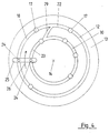
- the basic structure of such a device is outlined in Fig. 1.
- the device for forming a container consists in essentially from a blowing station (1), which with a Form (2) is provided, into which a preform (3) can be inserted is.
- the preform (3) can be an injection molded Be part of polyethylene terephthalate.
- the mold (2) consists of mold halves (4,5) and a bottom part (6) by a Lifting device (7) can be positioned.
- the preform (3) can be in the area of the blowing station (1) Transport mandrel (8) to be held together with the Preform (3) a plurality of treatment stations passes through within the device. It is also possible, the preform (3) for example using pliers or other handling means directly into the mold (2) to use.
- a connecting piston (9) arranged, which supplies the preform (3) with compressed air and at the same time a seal relative to the transport mandrel makes.
- the preform (3) is stretched with the help a stretching rod (10) which is supported by a cylinder (11) is positioned.
- a stretching rod (10) which is supported by a cylinder (11) is positioned.
- Curve segments are particularly useful if a plurality of blowing stations (1) on a rotating one Blow wheel are arranged.
- Cylinders (11) is useful when stationary Blow stations (1) are provided.
- Air grooves (12) made a control disc (13).
- the air grooves (12) run accordingly the representation in Fig. 4 radially to a center (14) of the control disc (13).
- the basic process can simpler the linear representation in Fig. 2nd and Fig. 3 are removed.
- Fig. 2 are two working grooves (15) and a storage groove (16) are provided.
- the air grooves (12) are separated by separating elements (17) partitioned off areas. This is it possible along the course of an air groove (12) Arrange pressure areas with different pressure levels.
- the one shown in Fig. 2 above Working groove (15) is starting from the first separating element (17) in the left area first a main segment (18) arranged, to which a transition segment (19) connects.
- the transition segment (19) is through a Cross bore (20) with a receiving segment (21) in the Storage groove (16) connected.
- the area of the main segment (18) can be, for example Pressure of about 6 bar can be provided in the range of Transfer segment (19) is carried out by air transfer a pressure reduction in the receiving segment (21) to about 3 bar.
- the pressure of 3 bar is in Maintain the area of the holding segment (22). in the A reduction takes place in the area of the venting segment (23) the pressure to ambient pressure.
- the feed of the respective pressures take place through removal bores (24) in the area of a take-off disc (25), which corresponds to the control disc (13) is arranged.
- the take-off washer (25) rotates relative to the stationary one Control disc (13) in the direction of a rotational orientation (26).
- the receiving segment (21) has a pressure accumulator in connection from which the stored compressed air at Need can be removed again.
- a transition the stored compressed air takes place, for example, in the Area of a removal segment (27) with a Dispensing segment (28) in the area of the one shown in FIG. 2 below Working groove (15) is arranged.
- Positioning In all process variants, the following can be used: that usually for holding a particular Positioning a lower pressure than one rapid adoption of the intended positioning required is. After taking the Positioning can therefore reduce the pressure. Can be taken into account in all procedural steps be different for certain directions of movement Positioning forces are required for example from material resistances to be deformed Material or the influence of weight forces result.
- Fig. 3 shows a method variant in which one Transfer of working air directly between the Working grooves (15) takes place. So here is none separate air storage provided. The transition takes place with the help of a connecting segment (29).
- the method variant according to FIG. 2 thus lies there is no coupling of blowing stations with each other, but only functions in the area of one individual blowing station coupled together. In the 3, however, is coupled several blowing stations together.
- the connecting segment (29) For Avoiding functional problems when starting up the Machine after a malfunction or when starting up for the first time it is appropriate to use the connecting segment (29) to arrange a supporting air segment (30).
- the supporting air segment (30) ensures that even if there is no transfer of compressed air With the help of the connecting element (29) the intended Function can be performed. Mechanical damage due to non-performed movement operations are avoided.
- main working air is turned off a main working air supply (31) via a main valve (32) in the area of a pneumatic component (33) directed.
- a main vent valve (34) and a main silencer (35) are provided.
- a transfer valve (36) After performing the intended movement with the help the main working air is through a transfer valve (36) a compressed air transfer to the area an auxiliary air supply (37).
- the compressed air transfer can with the activation of a pressure limiter (38) take place, the too high pressure in the Area of the secondary air supply (37) prevented.
- a compressed air reservoir can be used that absorbs the transferred compressed air.
- a pressure monitor (39) is connected in the area of secondary air supply (37) a pressure monitor (39) is connected. Auxiliary work air is supplied with the help a secondary air valve (40). To carry out a Ventilation in the area of the secondary working air is a Secondary ventilation valve (41) and a secondary silencer (42) provided.
- FIG. 6 A variant in which two different pneumatic Components (33) are coupled to one another, shows Fig. 6.
- the arrangement of the main air supply (31), the main valve (32), the main vent valve (34) and the main silencer (35) corresponds essentially to the embodiment 5.
- the transfer valve (36) takes place in the embodiment according to FIG. 6, however a transfer of main working air from the area of the pneumatic component (33) after the implementation an assigned work step in the area another pneumatic component (33) for Execution of a work step with a lower one Pressure level.
- the lower pressure level has in any embodiment not necessarily the result that also a less force for the subordinate work movement is required. It is known that in the area pneumatics the force exerted from the product of Pressure of the medium and the applied area. Becomes thus for the pneumatic piston in the area of the downstream pneumatic component a larger one Provided area, so is a corresponding greater power development possible. Because of the available standing pressure volume is, however, the one to be carried out Stroke in the area of downstream pneumatic Element with a single compressed air supply limited by the transfer valve (36). An increase in the possible stroke range can therefore by a separate additional supply of working air (37) that are not just one Storage function for compressed air from the area of Transfer valve (36) exerts but in the It is able to independently feed in secondary air.
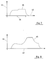
- FIG. 7 shows a pressure-time diagram.
- a time axis (43) and a pressure axis (44) are provided.
- the registered Pressure increase in the area of the changeover time (46) was arbitrarily assumed here whether a change in pressure occurs at this point and how big this, if any, depends on the amount of reconcilable Main working air and the function of pressure monitoring (39).
- Fig. 8 shows the corresponding pressure curve of the previous pneumatic component (33) with stretched Timeline (43).
- the pressure curve initially increases on and remains while performing the Lift movement due to flow effects initially on one about the same level. After reaching and holding the A first pressure reduction takes place at the final levels Compressed air transfer and then another Pressure reduction through ventilation to the environment.
Landscapes
- Engineering & Computer Science (AREA)
- Mechanical Engineering (AREA)
- Manufacturing & Machinery (AREA)
- Physics & Mathematics (AREA)
- Thermal Sciences (AREA)
- Life Sciences & Earth Sciences (AREA)
- Sustainable Development (AREA)
- Fluid Mechanics (AREA)
- General Engineering & Computer Science (AREA)
- Blow-Moulding Or Thermoforming Of Plastics Or The Like (AREA)
Claims (16)
- Procédé pour le fonctionnement pneumatique d'un dispositif dans le cas duquel pour l'actionnement pneumatique d'au moins un élément de construction (33), de l'air de travail principal est amené d'une source d'alimentation principale en air de travail (31) et dans le cas duquel, en plus de la source d'alimentation principale en air de travail (31), il est utilisé au moins une source d'alimentation secondaire en air de travail (37) qui présente un niveau de pression plus faible que celui de la source d'alimentation principale en air de travail (31), et dans le cas duquel , après l'exécution d'une opération de travail d'un élément de construction pneumatique que (33) grâce à une alimentation en air sous pression fournie par la source d'alimentation principale en air de travail (31), au cours d'une phase de transition, il est effectué une désaération dans la source d'alimentation secondaire en air de travail (37), et dans le cas duquel, après la phase de transition, il est effectué une désaération de l'élément de construction pneumatique (33) par rapport à une pression environnante et dans le cas duquel une deuxième opération de travail pneumatique est produite par une alimentation à partir de la source d'alimentation secondaire en air de travailler dans le cas duquel un récipient est fabriqué à partir d'une matière synthétique thermoplastique et une ébauche première formée (3) , après avoir été amenée à une température convenable, est amenée à un poste de soufflage (1) comportant une forme ou matrice de soufflage (2) qui a été prévue pour donner son profil au récipient et dans laquelle l'ébauche première formée (3) amenée à une température convenable est introduite, de même que dans le cas duquel, sous l'effet de l'arrivée d'air de soufflage, l'ébauche première formée est dilatée, le procédé étant caractérisé en ce que le récipient est étiré par une barre d'étirage (10) et en ce que par la source d'alimentation secondaire en air de travail (37), un cylindre d'étirage (11) qui positionne la barre d'étirage (10), au cours d'une partie au moins du mouvement de positionnement de la barre d'étirage (10), est alimenté par de l'air sous pression transféré de la source l'alimentation principale en air de travail (31) après exécution de la première opération de travail, à la source d' alimentation secondaire en air de travail (37).
- Procédé suivant la revendication 1, caractérisé en ce qu'une partie au moins de l'air de soufflage, après un formage du récipient, est transféré dans la zone de la source d'alimentation secondaire en air de travail (37).
- Procédé suivant l'une ou l'autre des revendications 1 et 2, caractérisé en ce qu'un mouvement de la barre d'étirage (10) en vue de l'étirage de l'ébauche première formée (3) est produit par alimentation par la source d'alimentation principale en air de travail (31) et en ce qu'une course de retour de la barre d'étirage (10) est produit par alimentation par la source d'alimentation secondaire en air de travail (37).
- Procédé suivant l'une quelconque des revendications 1 à 3, caractérisé en ce que lors de l'exécution des mouvements de positionnement à composante verticale, en ce qui concerne le choix des pressions nécessaires pour les mouvements de positionnement, il est tenu compte de la force de la pesanteur qui sollicite Les éléments de construction pour des directions de mouvements différentes.
- Procédé suivant l'une quelconque des revendications 1 à 4 caractérisé en ce que de l'air sous pression qui s'écoule de la zone de la source d'alimentation principale en air de travail (31) dans la zone de la source d'alimentation secondaire en air de travail (37) est emmagasiné au moins par moments.
- Procédé suivant l'une quelconque des revendications 1 à 5, caractérisé en ce que dans la zone d'un élément de construction pneumatique (33), qui est alimenté tant à partir de la source d'alimentation principale en air de travail (31) qu'à partir de la source d'alimentation secondaire en air de travail (37) pour assurer l'exécution de différents mouvements, il est utilisé un emmagasinage à air sous pression local pour de l'air de travail transféré.
- Procédé suivant l'une quelconque des revendications 1 à 6, caractérisé en ce que par le transfert d'air de travail principal prélevé d'un élément de construction pneumatique dans la zone d'un autre élément de construction pneumatique (33) il est effectué un accouplement de plusieurs éléments de construction, de construction essentiellement identique mais toutefois commandés en succession avec décalage de temps.
- Procédé suivant l'une quelconque des revendications 1 à 7, caractérisé en ce que dans la zone de la source d' alimentation secondaire en air de travail (37), il est prévu une alimentation en air de travail secondaire qui est indépendante du transfert d'air de travail principal s'écoulant de la zone de l'élément de construction pneumatique (33).
- Procédé suivant l'une quelconque des revendications 1 à 8, caractérisé en ce que l'élément de construction pneumatique (33) est actionné de telle façon que pour l'exécution d'un mouvement de positionnement subséquente il est utilisé tout d'abord de l'air sous pression transféré de la zone de la source d'alimentation principale en air de travail (31) et ensuite un air de travail secondaire s'écoulant d'une source d'air sous pression indépendante.
- Dispositif destiné à l'exécution d'opérations de travail par actionnement pneumatique, dans le cas duquel au moins un élément, de construction (33), pour l'actionnement, est relié à une source d'alimentation principale en air de travail (31) et dans le cas duquel, en plus de la source d'alimentation principale en air de travail (31), il a été prévu au moins une source d'alimentation secondaire en air de travail (37) qui présente un niveau de pression inférieur à celui de la source d'alimentation principale en air travail (31) et dans le cas duquel dans la zone d'un élément de raccordement qui relie l'élément de construction pneumatique (33) à la source d'alimentation principale en air de travail (31), il est prévu une commutation qui, au cours d'une phase principale, détermine le passage d'air de travail de la zone de la source d'alimentation principale en air de travail dans la zone d'un élément de construction pneumatique (33) et qui, après un achèvement de la phase principale, au cours d'une phase de transition, établit une liaison entre un élément de commande de l'élément de construction pneumatique (33) et la source d'alimentation secondaire en air de travail (37) pour le transfert d'air de travail, et dans le cas duquel l'élément de construction pneumatique (33) est relié à un élément de commande libre qui, après un achèvement de la phase de transition, désaère un espace interne de l'élément de commande par rapport à une pression environnante et dans le cas duquel à la source d'alimentation secondaire en air de travail (37) est relié au moins un autre élément de fonctionnement pneumatique, et dans le cas duquel, pour le formage d'un récipient à partir d'une matière synthétique thermoplastique, il est prévu au moins un poste de soufflage (1) qui est destiné à recevoir et à contenir une ébauche première formée (3) ayant été amenée à une température convenable, poste de soufflage (1) comportant une forme ou matrice de soufflage (2) qui présente un profil interne correspondant à celui du récipient à former et qui est muni d'une source d'alimentation en air de soufflage pour la dilatation de l'ébauche première formée (3), Le dispositif étant caractérisé en ce que pour l'étirage de l'ébauche première formée (3), il a été prévu une barre d'étirage (10) qui est positionnée par un cylindre d'étirage (11) et en ce que le cylindre d'étirage (11), au cours d'une partie au moins de l'exécution des mouvements de positionnement de la barre d'étirage (10), en tant qu'élément de fonctionnement pneumatique complémentaire,
pour l'alimentation en air de travail s'écoulant de la zone de l'élément de construction pneumatique (33), est relié à la source d'alimentation secondaire en air de travail (37). - Dispositif suivant la revendication 10, caractérisé en ce que pour l'exécution des opérations de commutation pneumatiques essentielles, il a été prévu un disque de commande (13) présentant des canaux à air sous forme de rainures (12), en correspondance duquel est guidé un disque récepteur (25), monté de façon à pouvoir tourner, qui présente des passages de réception (24).
- Dispositif suivant l'une ou l'autre des revendications 10 et 11, caractérisé en ce qu'au moins deux canaux à air sous forme de rainures (12) du disque de commande (13) sont réservés à des mouvements de travail différents à effectuer et en ce qu'un des mouvements de travail peut être effectué à une pression relativement élevée par rapport à l'exécution de l'autre mouvement de travail, en ce que les canaux de travail (15) sont subdivisés par des éléments de séparation (17) en segments délimités et séparés l'un par rapport à l'autre de façon à être étanches à la pression et en ce qu'au moins un segment de l'un des canaux à air sous forme de rainures (12), pour le transfert d'air sous pression, et relié à au moins un segment d'un canal à air sous forme de rainure (12) voisin.
- Dispositif suivant la revendication 10, caractérisé en ce que pour l'exécution des opérations de commutation, il a été prévu au moins une valve pouvant être commandée (32, 34, 36, 40, 41).
- Dispositif suivant la revendication 13, caractérisé en ce qu'au moins l'une des valves (32, 34, 36, 40, 41) a été prévue sous La forme d'une valve électromagnétique.
- Dispositif suivant l'une quelconque des revendications 10 à 14, caractérisé en ce que la source d'alimentation secondaire en air de travail (37) a été prévue comme alimentation directe pour un élément de construction pneumatique complémentaire (33).
- Dispositif suivant l'une quelconque des revendications 10 à 15, caractérisé en ce que dans la zone de la source d'alimentation secondaire en air de travail (37), pour la réduction des accouplements, il a été prévu une alimentation en air sous pression complémentaire indépendante avec source de pression séparée.
Applications Claiming Priority (2)
| Application Number | Priority Date | Filing Date | Title |
|---|---|---|---|
| DE4340290 | 1993-11-26 | ||
| DE4340290A DE4340290A1 (de) | 1993-11-26 | 1993-11-26 | Mehrfachnutzung von Arbeitsluft |
Publications (3)
| Publication Number | Publication Date |
|---|---|
| EP0655314A1 EP0655314A1 (fr) | 1995-05-31 |
| EP0655314B1 true EP0655314B1 (fr) | 1998-03-04 |
| EP0655314B2 EP0655314B2 (fr) | 2004-12-29 |
Family
ID=6503489
Family Applications (1)
| Application Number | Title | Priority Date | Filing Date |
|---|---|---|---|
| EP94118335A Expired - Lifetime EP0655314B2 (fr) | 1993-11-26 | 1994-11-22 | Utilisation multiple d'air de travail |
Country Status (4)
| Country | Link |
|---|---|
| US (1) | US5585066A (fr) |
| EP (1) | EP0655314B2 (fr) |
| JP (1) | JP3422860B2 (fr) |
| DE (2) | DE4340290A1 (fr) |
Families Citing this family (23)
| Publication number | Priority date | Publication date | Assignee | Title |
|---|---|---|---|---|
| EP0765213A1 (fr) * | 1995-02-17 | 1997-04-02 | ProControl AG | Procede de formage par etirage et par soufflage, et presse de formage par soufflage |
| TW289008B (en) * | 1995-07-18 | 1996-10-21 | A K Tech Lab Inc | Air operation method and device for an extention blow forming machine |
| GR960100152A (el) * | 1996-05-10 | 1998-01-30 | Μηχανη αποθηκευσεως χρησιμοποιηθεντος πεπιεσμενου αερος. | |
| NL1003827C2 (nl) * | 1996-08-19 | 1998-02-26 | Thomassen & Drijver | Inrichting voor het hermodelleren van een hol metalen voorwerp. |
| US5733100A (en) * | 1996-10-09 | 1998-03-31 | Plastipak Packaging, Inc. | Cylindrical object palletizer |
| FR2781716B1 (fr) * | 1998-07-29 | 2000-09-29 | Sidel Sa | Procede de fabrication par soufflage de corps creux en matiere plastique, dispositif et installation pour sa mise en oeuvre |
| FR2814392B1 (fr) * | 2000-09-25 | 2002-12-20 | Sidel Sa | Machine d'etirage-soufflage comportant une commande perfectionnee de la tige d'etirage |
| FR2827541B1 (fr) * | 2001-07-20 | 2005-07-01 | Technoplan Engineering S A | Dispositif de soufflage d'emballages |
| ES2186579B1 (es) * | 2001-10-16 | 2004-08-16 | Luis Jose Penalonga Teijeiro | Recuperacion de energia neumatica en instalaciones de aire comprimido. |
| DE202004021780U1 (de) * | 2004-03-25 | 2010-12-09 | Krones Ag | Vorrichtung zum Herstellen eines insbesondere wärmebeständigen Hohlkörpers |
| DE102004041973B3 (de) * | 2004-08-31 | 2006-01-19 | Krones Ag | Luftrecycling im Blasformprozess |
| FR2889993B1 (fr) * | 2005-08-23 | 2007-12-28 | Technoplan Engineering S A Sa | Procede de soufflage au moyen d'un gaz d'un emballage et installation de mise en oeuvre. |
| ITRM20060001A1 (it) * | 2006-01-04 | 2007-07-05 | Sipa Societa Industrializzazione | Processo ed impianto di produzione per soffiaggio di contenitori in plastica |
| FR2907186B1 (fr) * | 2006-10-16 | 2009-01-16 | Sidel Participations | Distributeur tournant de pression et machine carrousel de traitement de corps creux qui en est equipee |
| DE102007015105B4 (de) | 2007-03-29 | 2022-03-10 | Krones Aktiengesellschaft | Vorrichtung zum Blasformen |
| DE102008061492A1 (de) | 2008-12-10 | 2010-06-17 | Krones Ag | Verfahren und Vorrichtung zur ökonomischen Herstellung von Kunststoffbehältern |
| DE202009006684U1 (de) | 2009-05-08 | 2009-08-27 | Druckluft-Technik Chemnitz Gmbh | Vorrichtung zur Reduzierung der für den Blasformprozess erforderlichen Druckluft |
| DE102009041013A1 (de) * | 2009-09-10 | 2011-03-24 | Krones Ag | Verfahren und Vorrichtung zum Blasformen von Behältern |
| DE102010024277A1 (de) * | 2010-06-18 | 2011-12-22 | Krones Aktiengesellschaft | Blasmaschine mit Druckluftrecycling |
| JP5725643B2 (ja) * | 2010-10-14 | 2015-05-27 | 日精エー・エス・ビー機械株式会社 | ブロー成形装置の作動方法 |
| DE102011055153A1 (de) * | 2011-11-08 | 2013-05-08 | Krones Aktiengesellschaft | Blasmaschine mit automatischer Prozesswinkeloptimierung |
| CH710149A1 (de) * | 2014-09-25 | 2016-03-31 | Alpla Werke | Kunststoffbehälter, der durch ein Streckblasverfahren aus einem Preform hergestellt ist und Streckblasverfahren zur Herstellung eines Kunststoffbehälters aus einem Preform. |
| KR102164809B1 (ko) * | 2018-05-17 | 2020-10-14 | (주)이너보틀 | 용기 제조 방법 및 용기 제조 장치 |
Family Cites Families (15)
| Publication number | Priority date | Publication date | Assignee | Title |
|---|---|---|---|---|
| US2345082A (en) * | 1940-03-06 | 1944-03-28 | Waseige Charles Raymond | Plant for distributing air under pressure and in constituting parts thereof |
| US3275728A (en) * | 1962-12-04 | 1966-09-27 | Monsanto Co | Parison severing method |
| US3400636A (en) * | 1966-04-12 | 1968-09-10 | Ervin J. Schneider | Pneumatic circuit for rapidly transferring fluid under pressure from a work cylinderto a storage tank for subsequent use |
| US3888961A (en) * | 1972-10-06 | 1975-06-10 | Ingersoll Rand Co | Blow molding process including article cooling |
| GB1474044A (en) * | 1974-12-03 | 1977-05-18 | Ici Ltd | Plastics container manufacture |
| JPS5433566A (en) * | 1977-08-22 | 1979-03-12 | Toyo Seikan Kaisha Ltd | Drawing blow molding method |
| US4488863A (en) * | 1981-02-23 | 1984-12-18 | The Continental Group, Inc. | Recycling of blow air |
| GB2095759A (en) * | 1981-03-26 | 1982-10-06 | Rexnord Inc | Energy-conserving apparatus for a piston cylinder arrangement |
| DE3111925A1 (de) * | 1981-03-26 | 1982-10-07 | Robert Bosch Gmbh, 7000 Stuttgart | Verfahren und vorrichtung zum einsparen von druckluft, insbesondere bei thermoformmaschinen |
| US4498854A (en) * | 1982-10-13 | 1985-02-12 | Continental Packaging Company, Inc. | In-mold labeler--dual parison |
| US4790741A (en) † | 1987-08-07 | 1988-12-13 | Toyo Seikan Kaisha, Ltd. | Apparatus for preparing heat-set plastic hollow vessel |
| ATE83425T1 (de) * | 1988-09-26 | 1993-01-15 | Engel Gmbh Maschbau | Spritzgiessmaschine. |
| JP3153907B2 (ja) * | 1990-12-18 | 2001-04-09 | 弘料 吉岡 | ガス圧縮リサイクル装置 |
| DE4113874A1 (de) * | 1991-04-27 | 1992-10-29 | Krupp Corpoplast Masch | Vorrichtung zur blasverformung von kunststoff |
| US5244610A (en) * | 1992-02-14 | 1993-09-14 | Plastipak Packaging, Inc. | Rotary plastic blow molding |
-
1993
- 1993-11-26 DE DE4340290A patent/DE4340290A1/de not_active Withdrawn
-
1994
- 1994-11-22 DE DE59405374T patent/DE59405374D1/de not_active Expired - Lifetime
- 1994-11-22 EP EP94118335A patent/EP0655314B2/fr not_active Expired - Lifetime
- 1994-11-23 US US08/344,494 patent/US5585066A/en not_active Expired - Lifetime
- 1994-11-28 JP JP29348594A patent/JP3422860B2/ja not_active Expired - Fee Related
Also Published As
| Publication number | Publication date |
|---|---|
| EP0655314B2 (fr) | 2004-12-29 |
| DE4340290A1 (de) | 1995-06-01 |
| JPH07251443A (ja) | 1995-10-03 |
| EP0655314A1 (fr) | 1995-05-31 |
| US5585066A (en) | 1996-12-17 |
| JP3422860B2 (ja) | 2003-06-30 |
| DE59405374D1 (de) | 1998-04-09 |
Similar Documents
| Publication | Publication Date | Title |
|---|---|---|
| EP0655314B1 (fr) | Utilisation multiple d'air de travail | |
| EP0655313B1 (fr) | Utilisation multiple d'air de soufflage | |
| EP1727661B1 (fr) | Procede et dispositif pour produire un corps creux en reduisant la consommation d' air | |
| EP1974892A2 (fr) | Procédé destiné au moulage par soufflage | |
| DE102004045405A1 (de) | Vorrichtung zur Blasformung von Behältern | |
| EP3825097B1 (fr) | Dispositif de formage des préformes en matière plastique pour obtenir des récipients en matière plastique pourvu de soupape proportionnelle | |
| EP2653290B1 (fr) | Machine de formage par soufflage avec refroidissement du sol dans une phase de stabilisation | |
| EP2176053B2 (fr) | Dispositif de soufflage de récipients | |
| DE102014115645A1 (de) | Verfahren und Vorrichtung zum Umformen von Kunststoffvorformlingen mit Querschnittsveränderung eines Volumenstroms | |
| WO2012095063A2 (fr) | Procédé et dispositif de moulage par soufflage de récipients | |
| EP2412512A2 (fr) | Machine de soufflage-étirage avec compresseur intégré | |
| EP1868767B1 (fr) | Procede et dispositif de positionnement d'un composant | |
| EP4470749A1 (fr) | Procédé et dispositif de formage d'ébauches en plastique en récipients en plastique dotés de quatre niveaux de pression et de refroidissement du fond | |
| EP1531978B1 (fr) | Procede et dispositif de regulation pneumatique | |
| DE2703454A1 (de) | Verfahren und vorrichtung zum blasformen | |
| EP2054214B1 (fr) | Procédé et dispositif de formation de récipients par soufflage | |
| WO2019025550A1 (fr) | Dispositif et procédé pour mouler des préformes en matériau synthétique en récipients en matériau synthétique par thermorégulation du moule du fond | |
| EP1574318B1 (fr) | Procédé et appareil de formage de récipients par soufflage | |
| EP2803469B1 (fr) | Machine de formage par soufflage dotée d'une commande séparée de coussin de pression | |
| DE2504740A1 (de) | Vorrichtung und verfahren zur herstellung von zweiachsig ausgerichteten gegenstaenden durch blasformen | |
| DE102018105229A1 (de) | Vorrichtung und Verfahren zum Expandieren und gleichzeitigen Befüllen von Behältnissen | |
| DE102022109817A1 (de) | Ventilblock | |
| DE102018105228A1 (de) | Vorrichtung und Verfahren zum Expandieren und gleichzeitigen Befüllen von Behältnissen | |
| EP4134222A1 (fr) | Machine à souffler à commande de pression lors du processus de soufflage | |
| EP2044334B1 (fr) | Procede et dispositif de formage de recipients par soufflage |
Legal Events
| Date | Code | Title | Description |
|---|---|---|---|
| PUAI | Public reference made under article 153(3) epc to a published international application that has entered the european phase |
Free format text: ORIGINAL CODE: 0009012 |
|
| AK | Designated contracting states |
Kind code of ref document: A1 Designated state(s): CH DE ES FR GB IT LI |
|
| 17P | Request for examination filed |
Effective date: 19950630 |
|
| 17Q | First examination report despatched |
Effective date: 19961024 |
|
| GRAG | Despatch of communication of intention to grant |
Free format text: ORIGINAL CODE: EPIDOS AGRA |
|
| GRAG | Despatch of communication of intention to grant |
Free format text: ORIGINAL CODE: EPIDOS AGRA |
|
| GRAH | Despatch of communication of intention to grant a patent |
Free format text: ORIGINAL CODE: EPIDOS IGRA |
|
| GRAH | Despatch of communication of intention to grant a patent |
Free format text: ORIGINAL CODE: EPIDOS IGRA |
|
| GRAA | (expected) grant |
Free format text: ORIGINAL CODE: 0009210 |
|
| AK | Designated contracting states |
Kind code of ref document: B1 Designated state(s): CH DE ES FR GB IT LI |
|
| PG25 | Lapsed in a contracting state [announced via postgrant information from national office to epo] |
Ref country code: IT Free format text: LAPSE BECAUSE OF FAILURE TO SUBMIT A TRANSLATION OF THE DESCRIPTION OR TO PAY THE FEE WITHIN THE PRESCRIBED TIME-LIMIT;WARNING: LAPSES OF ITALIAN PATENTS WITH EFFECTIVE DATE BEFORE 2007 MAY HAVE OCCURRED AT ANY TIME BEFORE 2007. THE CORRECT EFFECTIVE DATE MAY BE DIFFERENT FROM THE ONE RECORDED. Effective date: 19980304 Ref country code: GB Free format text: LAPSE BECAUSE OF FAILURE TO SUBMIT A TRANSLATION OF THE DESCRIPTION OR TO PAY THE FEE WITHIN THE PRESCRIBED TIME-LIMIT Effective date: 19980304 Ref country code: FR Free format text: LAPSE BECAUSE OF FAILURE TO SUBMIT A TRANSLATION OF THE DESCRIPTION OR TO PAY THE FEE WITHIN THE PRESCRIBED TIME-LIMIT Effective date: 19980304 Ref country code: ES Free format text: THE PATENT HAS BEEN ANNULLED BY A DECISION OF A NATIONAL AUTHORITY Effective date: 19980304 |
|
| REG | Reference to a national code |
Ref country code: CH Ref legal event code: EP |
|
| REF | Corresponds to: |
Ref document number: 59405374 Country of ref document: DE Date of ref document: 19980409 |
|
| EN | Fr: translation not filed | ||
| GBV | Gb: ep patent (uk) treated as always having been void in accordance with gb section 77(7)/1977 [no translation filed] |
Effective date: 19980304 |
|
| PG25 | Lapsed in a contracting state [announced via postgrant information from national office to epo] |
Ref country code: LI Free format text: LAPSE BECAUSE OF NON-PAYMENT OF DUE FEES Effective date: 19981130 Ref country code: CH Free format text: LAPSE BECAUSE OF NON-PAYMENT OF DUE FEES Effective date: 19981130 |
|
| PLBQ | Unpublished change to opponent data |
Free format text: ORIGINAL CODE: EPIDOS OPPO |
|
| PLBI | Opposition filed |
Free format text: ORIGINAL CODE: 0009260 |
|
| PLBQ | Unpublished change to opponent data |
Free format text: ORIGINAL CODE: EPIDOS OPPO |
|
| PLBI | Opposition filed |
Free format text: ORIGINAL CODE: 0009260 |
|
| PLBF | Reply of patent proprietor to notice(s) of opposition |
Free format text: ORIGINAL CODE: EPIDOS OBSO |
|
| 26 | Opposition filed |
Opponent name: SIDEL S.A. Effective date: 19981204 |
|
| 26 | Opposition filed |
Opponent name: KRONES AG Effective date: 19981204 Opponent name: SIDEL S.A. Effective date: 19981204 |
|
| PLBF | Reply of patent proprietor to notice(s) of opposition |
Free format text: ORIGINAL CODE: EPIDOS OBSO |
|
| RAP2 | Party data changed (patent owner data changed or rights of a patent transferred) |
Owner name: KRUPP CORPOPLAST MASCHINENBAU GMBH |
|
| PLBF | Reply of patent proprietor to notice(s) of opposition |
Free format text: ORIGINAL CODE: EPIDOS OBSO |
|
| RAP2 | Party data changed (patent owner data changed or rights of a patent transferred) |
Owner name: WEISS, RONALD |
|
| RIN2 | Information on inventor provided after grant (corrected) |
Free format text: WEISS, RONALD |
|
| REG | Reference to a national code |
Ref country code: CH Ref legal event code: PL |
|
| PLBF | Reply of patent proprietor to notice(s) of opposition |
Free format text: ORIGINAL CODE: EPIDOS OBSO |
|
| RAP2 | Party data changed (patent owner data changed or rights of a patent transferred) |
Owner name: KRONES AG |
|
| RIN2 | Information on inventor provided after grant (corrected) |
Free format text: KRONES AG |
|
| PLBO | Opposition rejected |
Free format text: ORIGINAL CODE: EPIDOS REJO |
|
| APAC | Appeal dossier modified |
Free format text: ORIGINAL CODE: EPIDOS NOAPO |
|
| APAE | Appeal reference modified |
Free format text: ORIGINAL CODE: EPIDOS REFNO |
|
| APAC | Appeal dossier modified |
Free format text: ORIGINAL CODE: EPIDOS NOAPO |
|
| APBU | Appeal procedure closed |
Free format text: ORIGINAL CODE: EPIDOSNNOA9O |
|
| PUAH | Patent maintained in amended form |
Free format text: ORIGINAL CODE: 0009272 |
|
| STAA | Information on the status of an ep patent application or granted ep patent |
Free format text: STATUS: PATENT MAINTAINED AS AMENDED |
|
| 27A | Patent maintained in amended form |
Effective date: 20041229 |
|
| AK | Designated contracting states |
Kind code of ref document: B2 Designated state(s): CH DE ES FR GB IT LI |
|
| REG | Reference to a national code |
Ref country code: ES Ref legal event code: FD2A Effective date: 19981123 |
|
| APAH | Appeal reference modified |
Free format text: ORIGINAL CODE: EPIDOSCREFNO |
|
| EN | Fr: translation not filed | ||
| PGFP | Annual fee paid to national office [announced via postgrant information from national office to epo] |
Ref country code: DE Payment date: 20131120 Year of fee payment: 20 |
|
| REG | Reference to a national code |
Ref country code: DE Ref legal event code: R071 Ref document number: 59405374 Country of ref document: DE |