EP0655315A2 - Verfahren zum Steuern des Formdruckes zum Druckluftformen eines Artikels aus thermoplastischer Kunststoffolie und Vorrichtung zur Durchführung des Verfahrens - Google Patents
Verfahren zum Steuern des Formdruckes zum Druckluftformen eines Artikels aus thermoplastischer Kunststoffolie und Vorrichtung zur Durchführung des Verfahrens Download PDFInfo
- Publication number
- EP0655315A2 EP0655315A2 EP94118278A EP94118278A EP0655315A2 EP 0655315 A2 EP0655315 A2 EP 0655315A2 EP 94118278 A EP94118278 A EP 94118278A EP 94118278 A EP94118278 A EP 94118278A EP 0655315 A2 EP0655315 A2 EP 0655315A2
- Authority
- EP
- European Patent Office
- Prior art keywords
- pressure
- air
- mold
- molding
- proportional valve
- Prior art date
- Legal status (The legal status is an assumption and is not a legal conclusion. Google has not performed a legal analysis and makes no representation as to the accuracy of the status listed.)
- Granted
Links
Images

Classifications
-
- B—PERFORMING OPERATIONS; TRANSPORTING
- B29—WORKING OF PLASTICS; WORKING OF SUBSTANCES IN A PLASTIC STATE IN GENERAL
- B29C—SHAPING OR JOINING OF PLASTICS; SHAPING OF MATERIAL IN A PLASTIC STATE, NOT OTHERWISE PROVIDED FOR; AFTER-TREATMENT OF THE SHAPED PRODUCTS, e.g. REPAIRING
- B29C51/00—Shaping by thermoforming, i.e. shaping sheets or sheet like preforms after heating, e.g. shaping sheets in matched moulds or by deep-drawing; Apparatus therefor
- B29C51/26—Component parts, details or accessories; Auxiliary operations
- B29C51/46—Measuring, controlling or regulating
-
- B—PERFORMING OPERATIONS; TRANSPORTING
- B29—WORKING OF PLASTICS; WORKING OF SUBSTANCES IN A PLASTIC STATE IN GENERAL
- B29C—SHAPING OR JOINING OF PLASTICS; SHAPING OF MATERIAL IN A PLASTIC STATE, NOT OTHERWISE PROVIDED FOR; AFTER-TREATMENT OF THE SHAPED PRODUCTS, e.g. REPAIRING
- B29C2791/00—Shaping characteristics in general
- B29C2791/004—Shaping under special conditions
- B29C2791/006—Using vacuum
-
- B—PERFORMING OPERATIONS; TRANSPORTING
- B29—WORKING OF PLASTICS; WORKING OF SUBSTANCES IN A PLASTIC STATE IN GENERAL
- B29C—SHAPING OR JOINING OF PLASTICS; SHAPING OF MATERIAL IN A PLASTIC STATE, NOT OTHERWISE PROVIDED FOR; AFTER-TREATMENT OF THE SHAPED PRODUCTS, e.g. REPAIRING
- B29C51/00—Shaping by thermoforming, i.e. shaping sheets or sheet like preforms after heating, e.g. shaping sheets in matched moulds or by deep-drawing; Apparatus therefor
- B29C51/10—Forming by pressure difference, e.g. vacuum
Definitions
- the invention relates to a method for controlling the molding pressure for compressed air molding an article made of thermoplastic material according to the preamble of the main claim and a device for performing the method.
- the molding pressure for compressed air molding is set in a known manner on a pressure control valve.
- pressure control valves have a relatively large resistance, so that flow losses must be expected. Characteristically, their cross-section narrows more and more with increasing secondary pressure, so that the resistance increases and the air volume becomes smaller and smaller. In practice, a period of the order of 0.5 seconds passes until a set mold pressure of approx. 5 bar has resulted from opening a valve in the mold air supply line.
- the invention has for its object to improve the method of the air supply so that the predetermined mold pressure can be reproduced very quickly without exceeding the predetermined value, which should result in a significant reduction in cycle time.
- This form printing should be able to be stored in the control so that the value for the form printing is automatically specified when a forming program is called for a specific article.
- the device for carrying out the method should be designed so that the method according to the invention can be carried out, if necessary, on both halves of the molding tool.
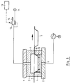
- the method according to the invention is used in a device for deep-drawing a section of a heated film web 7. It has two mold tables 1, 2 which can be moved relative to one another, each of which carries a mold half 3, 4. One mold half 4 has the shape of the article to be manufactured, the other mold half 3 acts as a pressure bell. The latter has a space 6, into which compressed air is supplied and in which the molding pressure builds up, which serves to press the film web 7 against the molding wall 8. The molding can be supported by vacuum, which is guided through the connection 9 and holes 10 to the mold wall 8.
- the molding pressure is formed from the network pressure prevailing in the compressed air network 11, in which the compressed air is supplied on the input side to a known proportional valve 12.
- the proportional valve 12 On the output side, the proportional valve 12 is connected to the molding table 1 and via holes to the molding space 6.
- the control of the proportional valve 12 takes place in accordance with the predetermined molding pressure with a corresponding control signal. If the proportional valve 12 is activated with this signal, it opens the feed line to the molding space 6 completely, so that compressed air flows in quickly from the network 11. If the mold pressure approaches the given one Value, the proportional valve 12 closes accordingly in time so that the mold pressure does not overshoot beyond the specified value, but in such a short time that the specified mold pressure is reached in the shortest possible time. After the molding process, the proportional valve 12 releases the molding air via an outlet 14 into the open. By providing the proportional valve with this outlet, additional vent valves are not required.
- a device for performing the method is usually constructed so that the two mold halves 3, 4 can be optionally mounted on the upper or lower mold table 1, 2.
- a line 15, 16 leads from the network 11 to the two molding tables 1, 2.
- a proportional valve 17, 18 is arranged in the line 15, 16, behind which a solenoid valve 19, 20 is arranged.
- these solenoid valves 19, 20 also have a second input-side connection for a vacuum line 21. They can be switched between a first position - compressed air connected to the shaping tables 1, 2 - and a second position - vacuum with the shaping tables 1, 2 connected.
- the two proportional valves 19, 20 work as follows: During the molding process, molding air flows through the proportional valve 17 and the solenoid valve 19 to the mold half 3. The valve 19 always remains in this position. At the same time, the proportional valve 20 is in the position that vacuum is applied to the molded part 4. After molding, the proportional valve 17 vents the molding space 8 outdoors. The valve 20 switches from vacuum to compressed air and the proportional valve 18 opens to supply the demolding air until the predetermined demolding air pressure is reached.
- the proportional valves 17, 18 therefore have two functions - depending on which molded part half 3, 4 they are assigned to: supplying the molding air or supplying the demolding air. Both can be done in the required manner with a given pressure.
Landscapes
- Engineering & Computer Science (AREA)
- Mechanical Engineering (AREA)
- Blow-Moulding Or Thermoforming Of Plastics Or The Like (AREA)
- Moulds For Moulding Plastics Or The Like (AREA)
- Casting Or Compression Moulding Of Plastics Or The Like (AREA)
Abstract
Description
- Die Erfindung betrifft ein Verfahren zum Steuern des Formdruckes zum Druckluftformen eines Artikels aus thermoplastischem Kunststoff nach dem Oberbegriff des Hauptanspruches und eine Vorrichtung zur Durchführung des Verfahrens.
- Je nach der Gestalt des herzustellenden Artikels, der Folienart, Foliendicke und Folientemperatur sind unterschiedliche Formdrücke erforderlich bzw. verfahrenstechnisch vorteilhaft. Man wählt den Formdruck nicht höher als nötig, da Druckluft Geld kostet und Druckaufbau und Druckabbau Zeit erfordern und sich damit auf die Taktzeit negativ auswirken.
- Der Formdruck zum Druckluftformen wird in bekannter Weise an einem Druckregelventil eingestellt. Solche Druckregelventile haben einen relativ großen Widerstand, so daß mit Strömungsverlusten gerechnet werden muß. Von der Charakteristik her verengt sich ihr Querschnitt mit steigendem Sekundärdruck immer mehr, so daß der Widerstand größer und die Luftmenge immer kleiner wird. Bis sich vom Öffnen eines Ventils in der Formluftzuleitung ein eingestellter Formdruck von ca. 5 bar ergeben hat, vergeht in der Praxis eine Zeitspanne in der Größenordnung von 0,5 Sekunden.
- Aus der DE-AS 14 54 962 ist es bekannt, statt eines Druckregelventiles einen Druckschalter in die Formluftzuleitung einzubauen, der bei Erreichen des vorgegebenen Formdruckes die Formluftzufuhr durch Schließen eines Ventils unterbindet. Die Nachteile des Druckregelventiles sind damit zwar vermieden, doch haben Versuche gezeigt, daß auf diese Weise keine reproduzierbaren und genauen Werte für den Formdruck erreicht werden können. Dies liegt zum einen an der Trägheit des Systems. Wenn der Druckschalter den vorgegebenen Wert meldet, wird dieses Signal in der Steuerung dazu verwendet, ein Magnetventil zum Schließen zu veranlassen. Ein solches Magnetventil hat aber bauartbedingt immer eine Verzögerungszeit, bis es ganz geschlossen ist. In dieser Zeit strömt weiter Luft ein, d. h. der Formdruck steigt immer über den am Druckschalter eingestellten Wert hinaus. Je nach Netzdruck - dieser schwankt in der Regel in der Größenordnung von 1 bar - ist dieser den vorgegebenen Druck übersteigenden Wert nicht konstant und wird noch von unterschiedlichen Verzögerungszeiten des Magnetventils, die ebenfalls netzdruckabhängig sein können, beeinflußt. Ungleiche Formdrücke haben aber eine unterschiedliche Qualität der geformten Artikel zur Folge, was nicht akzeptiert wird.
- Der Erfindung liegt die Aufgabe zugrunde, das Verfahren der Formluftzufuhr so zu verbessern, daß der vorgegebene Formdruck sehr rasch reproduzierbar erreicht wird, ohne den vorgegebenen Wert zu übersteigen, wodurch sich eine deutliche Verkürzung der Taktzeit ergeben sollte. Dieser Formdruck sollte in der Steuerung abgespeichert werden können, so daß bei Aufruf eines Formungsprogrammes für einen bestimmten Artikel auch der Wert für den Formdruck automatisch vorgegeben wird.
- Die Vorrichtung zur Durchführung des Verfahrens sollte so ausgebildet sein, daß das erfindungsgemäße Verfahren durchgeführt werden kann und zwar bei Bedarf an beiden Hälften des Formwerkzeuges. Vorzugsweise auch dann, wenn Vakuum zur Unterstützung des Formungsprozesses eingesetzt wird und ein Entformen der geformten Artikel über Entformluft erfolgt.
- Gelöst ist diese Aufgabe erfindungsgemäß durch die im Kennzeichen des Hauptanspruches angegebenen Maßnahmen bezüglich des Verfahrens sowie durch die Merkmale des Anspruches 3 bezüglich der Vorrichtung zur Durchführung des Verfahrens.
- Die anderen Ansprüche stellen vorteilhafte Weiterbildungen der Erfindung dar.
- Ein Ausführungsbeispiel der Erfindung ist anhand der schematischen Zeichnungen näher beschrieben. Es zeigt:
- Figur 1 -
- einen Querschnitt durch ein Formwerkzeug
- Figur 2 -
- einen Querschnitt durch das Formwerkzeug, wobei eine Umschaltung zwischen Oberteil und Unterteil erfolgen kann, und wobei der Formprozess durch Vakuum unterstützt wird.
- Das erfindungsgemäße Verfahren findet Anwendung bei einer Vorrichtung zum Tiefziehen eines Abschnittes einer erwärmten Folienbahn 7. Sie weist zwei zueinander verschiebbare Formtische 1, 2 auf, von denen jeder eine Formhälfte 3, 4 trägt. Eine Formhälfte 4 weist dabei die Form des herzustellenden Artikels auf, die andere Formhälfte 3 wirkt als Druckglocke. Letztere weist einen Raum 6 auf, in den Druckluft zugeführt wird und in dem sich der Formdruck aufbaut, der dazu dient, die Folienbahn 7 gegen die Formwand 8 zu drücken. Das Formen kann durch Vakuum unterstützt werden, das über den Anschluß 9 und Bohrungen 10 bis zur Formwand 8 geführt wird.
- Der Formdruck wird aus dem im Druckluftnetz 11 herrschenden Netzdruck gebildet, in dem die Druckluft einem an sich bekannten Proportionalventil 12 eingangsseitig zugeführt wird. Ausgangsseitig steht das Proportionalventil 12 mit dem Formtisch 1 und über Bohrungen mit dem Formraum 6 in Verbindung. Von der Steuerung 13 aus erfolgt die Ansteuerung des Proportionalventiles 12 entsprechend des vorgegebenen Formdruckes mit einem entsprechenden Steuersignal. Wird das Proportionalventil 12 mit diesem Signal angesteuert, öffnet es die Zuleitung zum Formraum 6 völlig, so daß rasch Druckluft vom Netz 11 einströmt. Nähert sich der Formdruck dem vorgegebenen Wert, schließt das Proportionalventil 12 entsprechend so rechtzeitig, daß kein Überschwingen des Formdruckes über den vorgegebenen Wert hinaus erfolgt, aber doch so kurzfristig, daß der vorgegebene Formdruck in kürzest möglicher Zeit erreicht wird. Nach dem Formvorgang entläßt das Proportionalventil 12 die Formluft über einen Ausgang 14 ins Freie. Indem das Proportionalventil mit diesem Ausgang versehen ist, sind zusätzliche Entlüftungsventile nicht erforderlich.
- Eine Vorrichtung zur Durchführung des Verfahrens ist in der Regel so aufgebaut, daß die beiden Formhälften 3, 4 wahlweise am oberen oder unteren Formtisch 1, 2 angebaut sein können. Man wählt die Anordnung entsprechend der gewünschten Lage des geformten Artikels 5. Dies ist wichtig im Hinblick auf Ausstanzen bzw. Stapeln der Artikel 5. Um Umbauten der Verrohrung beim Werkzeugwechsel zu vermeiden, wird in Weiterbildung der Erfindung vorgeschlagen, beide Formtische 1, 2 mit einem Proportionalventil 17, 18 zu verbinden (siehe Figur 2). Das Umstellen der Maschine erfolgt dann allein durch Vorgabe in der Steuerung.
- Da dann abwechselnd Vakuum und Formluft an den Formtischen 1, 2 zur Verfügung stehen muß, und nach dem Formen der Artikel 5 zum Lösen der Artikel 5 von der Formwand 8 ein geringer Luftstoß zugeführt werden sollte, wird gemäß Figur 2 folgender Aufbau vorgeschlagen:
Vom Netz 11 führt je eine Leitung 15, 16 zu den beiden Formtischen 1, 2. In der Leitung 15, 16 ist jeweils ein Proportionalventil 17, 18, dahinter ein Magnetventil 19, 20 angeordnet. Diese Magnetventile 19, 20 haben außer dem Anschluß für die Druckluft auch einen zweiten eingangsseitigen Anschluß für eine Vakuumleitung 21. Sie sind umschaltbar zwischen einer ersten Stellung - Druckluft mit den Formtischen 1, 2 verbunden - und einer zweiten Stellung - Vakuum mit den Formtischen 1, 2 verbunden. Im dargestellten Beispiel arbeiten die beiden Proportionalventile 19, 20 wie folgt:
Während des Formprozesses strömt Formluft durch das Proportionalventil 17 und das Magnetventil 19 zur Formhälfte 3.
Das Ventil 19 bleibt immer in dieser Stellung. Gleichzeitig steht das Proportionalventil 20 in der Stellung, daß Vakuum am Formteil 4 anliegt. Nach dem Formen entlüftet das Proportionalventil 17 den Formraum 8 ins Freie. Das Ventil 20 schaltet um von Vakuum auf Druckluft und das Proportionalventil 18 öffnet zur Zuführung der Entformluft bis zum Erreichen des vorgegebenen Entformluftdruckes. - Die Proportionalventile 17, 18 haben also zweierlei Funktionen - je nachdem, welcher Formteilhälfte 3, 4 sie zugeordnet sind: Zufuhr der Formluft oder Zufuhr der Entformluft. Beides kann in der erforderlichen Weise mit einem vorgegebenen Druck erfolgen.
Claims (6)
- Verfahren zum Steuern des Formdruckes zum Druckluftformen eines Artikels aus einer erwärmten thermoplastischen Kunststoffolie, die dabei in eine Form tiefgezogen wird, dadurch gekennzeichnet, daß ein dem in der Steuerung vorgegebenen Formdruck entsprechendes Signal auf ein in der Zuleitung der Formluft angeordnetes Proportionalventil (12, 17) einwirkt, so daß dieses die Formluft zunächst im vollen Querschnitt freigibt, diesen bei Annäherung an den vorgegebenen Formdruck drosselt und bei Erreichen des Formdruckes absperrt.
- Verfahren nach Anspruch 1 dadurch gekennzeichnet, daß das Zuführen der Entformluft zur Formhälfte (4) mit der Form des herzustellenden Artikels (5) ebenfalls über ein Proportionalventil (18) erfolgt, dem ein Steuersignal von der Steuerung entsprechend des vorgegebenen Entformdruckes zugeführt wird.
- Vorrichtung zur Durchführung des Verfahrens nach Anspruch 1 mit zwei relativ zueinander verschiebbaren Formtischen zur Aufnahme der beiden Formhälften, dadurch gekennzeichnet, daß in die Zuleitung der Formluft ein Proportionalventil (12, 17) eingebaut ist, auf das ein dem in der Steuerung vorgegebenen Formdruck entsprechendes Steuersignal einwirkt.
- Vorrichtung nach Anspruch 3 dadurch gekennzeichnet, daß in der Zuleitung (16) der Entformluft ein Proportionalventil (18) angeordnet ist, auf das ein dem in der Steuerung vorgegebenen Entformdruck entsprechendes Steuersignal einwirkt.
- Vorrichtung nach Anspruch 4 dadurch gekennzeichnet, daß in die Zuleitungen für Formluft und Entformluft ein Ventil (19, 20) eingebaut ist, das eingangsseitig einen Anschluß für Vakuum aufweist.
- Vorrichtung nach einem der Ansprüche 3 bis 5 dadurch gekennzeichnet, daß die Proportionalventile (12, 17, 18) einen Auslaß (14) für die Formluft aufweisen.
Applications Claiming Priority (2)
| Application Number | Priority Date | Filing Date | Title |
|---|---|---|---|
| DE4340449A DE4340449C2 (de) | 1993-11-27 | 1993-11-27 | Verfahren zum Steuern des Formdruckes zum Druckluftformen eines Artikels aus thermoplastischer Kunststoffolie und Vorrichtung zur Durchführung des Verfahrens |
| DE4340449 | 1993-11-27 |
Publications (3)
| Publication Number | Publication Date |
|---|---|
| EP0655315A2 true EP0655315A2 (de) | 1995-05-31 |
| EP0655315A3 EP0655315A3 (de) | 1996-11-27 |
| EP0655315B1 EP0655315B1 (de) | 1999-03-17 |
Family
ID=6503594
Family Applications (1)
| Application Number | Title | Priority Date | Filing Date |
|---|---|---|---|
| EP94118278A Expired - Lifetime EP0655315B1 (de) | 1993-11-27 | 1994-11-21 | Verfahren zum Steuern des Formdruckes zum Druckluftformen eines Artikels aus thermoplastischer Kunststoffolie und Vorrichtung zur Durchführung des Verfahrens |
Country Status (4)
| Country | Link |
|---|---|
| EP (1) | EP0655315B1 (de) |
| AT (1) | ATE177679T1 (de) |
| DE (2) | DE4340449C2 (de) |
| ES (1) | ES2131141T3 (de) |
Cited By (1)
| Publication number | Priority date | Publication date | Assignee | Title |
|---|---|---|---|---|
| CN102229241A (zh) * | 2011-06-03 | 2011-11-02 | 河北亚大汽车塑料制品有限公司 | 用于热塑性管的蒸汽成型设备和蒸汽成型方法 |
Families Citing this family (3)
| Publication number | Priority date | Publication date | Assignee | Title |
|---|---|---|---|---|
| DE102012208137B4 (de) * | 2012-05-15 | 2017-01-12 | Marbach Werkzeugbau Gmbh | Thermoformwerkzeug zur Herstellung von becherförmigen Gegenständen aus einer erwärmten Kunststofffolie |
| EP2853375B1 (de) | 2013-09-27 | 2018-12-26 | Gabler Thermoform GmbH & Co. KG | Verfahren zum Betreiben einer Thermoformmaschine und Thermoformmaschine |
| DE102013022072B4 (de) | 2013-12-23 | 2018-04-19 | Illig Maschinenbau Gmbh & Co. Kg | Verfahren zum Betreiben einer Thermoformmaschine |
Family Cites Families (1)
| Publication number | Priority date | Publication date | Assignee | Title |
|---|---|---|---|---|
| US3346923A (en) * | 1963-07-10 | 1967-10-17 | Brown Machine Co Of Michigan | Differential pressure forming machine |
-
1993
- 1993-11-27 DE DE4340449A patent/DE4340449C2/de not_active Expired - Fee Related
-
1994
- 1994-11-21 AT AT94118278T patent/ATE177679T1/de not_active IP Right Cessation
- 1994-11-21 ES ES94118278T patent/ES2131141T3/es not_active Expired - Lifetime
- 1994-11-21 DE DE59407955T patent/DE59407955D1/de not_active Expired - Fee Related
- 1994-11-21 EP EP94118278A patent/EP0655315B1/de not_active Expired - Lifetime
Cited By (1)
| Publication number | Priority date | Publication date | Assignee | Title |
|---|---|---|---|---|
| CN102229241A (zh) * | 2011-06-03 | 2011-11-02 | 河北亚大汽车塑料制品有限公司 | 用于热塑性管的蒸汽成型设备和蒸汽成型方法 |
Also Published As
| Publication number | Publication date |
|---|---|
| EP0655315A3 (de) | 1996-11-27 |
| DE4340449A1 (de) | 1995-06-01 |
| ATE177679T1 (de) | 1999-04-15 |
| ES2131141T3 (es) | 1999-07-16 |
| EP0655315B1 (de) | 1999-03-17 |
| DE59407955D1 (de) | 1999-04-22 |
| DE4340449C2 (de) | 1996-05-23 |
Similar Documents
| Publication | Publication Date | Title |
|---|---|---|
| EP0371974B1 (de) | Hubsauger für eine transporteinrichtung | |
| DE2732563C3 (de) | Ventilblock zur Steuerung von Glasformmaschinen | |
| DE3603108A1 (de) | Vorrichtung zum herstellen von formlingen aus aufgeschaeumtem kunststoff | |
| DE3111925A1 (de) | Verfahren und vorrichtung zum einsparen von druckluft, insbesondere bei thermoformmaschinen | |
| DE2708901A1 (de) | Verfahren zur verformung einer tafel, folie o.dgl. aus thermoplastischem material sowie vorrichtung zur durchfuehrung des verfahrens | |
| DE10006130B4 (de) | Steuereinheit für den pneumatischen Teil einer IS-Glasformungsmaschine | |
| DE202019100162U1 (de) | Spritzgusswerkzeug für die Herstellung von Behältern aus Kunststoff | |
| DE19843339B4 (de) | Verfahren und Vorrichtung zur Herstellung von Kunststoffrohren | |
| DE102019127516A1 (de) | Tiefzieheinrichtung zum Tiefziehen von Verpackungskörpern, z.B. Verpackungsschalen, aus Tiefziehfolie | |
| EP0655315B1 (de) | Verfahren zum Steuern des Formdruckes zum Druckluftformen eines Artikels aus thermoplastischer Kunststoffolie und Vorrichtung zur Durchführung des Verfahrens | |
| DE102007037748B3 (de) | Formwerkzeug und Verfahren zum Tiefziehen von Behältern aus einer erwärmten Folienbahn aus thermoplastischem Kunststoff | |
| EP0252470B1 (de) | Verfahren und Formwerkzeug zum Herstellen von mit textilen Überzügen versehenen Polstern aus Schaumstoff | |
| DE2523303A1 (de) | Vorrichtung zur hydraulischen steuerung des spritzdrucks, nachdrucks und staudrucks von spritzgiessmaschinen | |
| EP1361036A1 (de) | Formwerkzeug zum Tiefziehen von Behältern aus thermoplastischem Kunststoff,Stempel mit integriertem Ventil | |
| EP1342680A2 (de) | Verfahren zum Einstellen der Verfahrwege einer Stapeleinrichtung und Stapeleinrichtung zum Durchführen des Verfahrens | |
| DE10220701A1 (de) | Formwerkzeug zum Tiefziehen von Behältern aus thermoplastischem Kunststoff | |
| EP0525483A1 (de) | Formwerkzeug zur Herstellung von Kunststoffbechern | |
| CH645297A5 (de) | Spritzgussmaschine und verfahren zu ihrem betrieb. | |
| DE3931597C2 (de) | ||
| DE19726768C2 (de) | Verfahren zum Kühlen eines Behälters aus thermoplastischem Kunststoff und Vorrichtung zur Durchführung des Verfahrens | |
| CH467144A (de) | Verfahren und Vorrichtung zum Herstellen flaschenartiger Behälter aus Kunststoff | |
| EP2853375B1 (de) | Verfahren zum Betreiben einer Thermoformmaschine und Thermoformmaschine | |
| EP1002960A2 (de) | Pressdruckregelvorrichtung für einen Antriebszylinder eines Werkzeugs oder Werkzeugteils einer IS-Glasmaschine | |
| DE1285169B (de) | Vorrichtung zum Herstellen von becher- oder schalenfoermigen Behaeltern aus einer Kunststoff-Folienbahn | |
| DE2636463A1 (de) | Vorrichtung zum verformen von platten aus thermoplastischem kunststoff |
Legal Events
| Date | Code | Title | Description |
|---|---|---|---|
| PUAI | Public reference made under article 153(3) epc to a published international application that has entered the european phase |
Free format text: ORIGINAL CODE: 0009012 |
|
| AK | Designated contracting states |
Kind code of ref document: A2 Designated state(s): AT DE ES FR GB IT |
|
| PUAL | Search report despatched |
Free format text: ORIGINAL CODE: 0009013 |
|
| AK | Designated contracting states |
Kind code of ref document: A3 Designated state(s): AT DE ES FR GB IT |
|
| 17P | Request for examination filed |
Effective date: 19961112 |
|
| 17Q | First examination report despatched |
Effective date: 19980616 |
|
| GRAG | Despatch of communication of intention to grant |
Free format text: ORIGINAL CODE: EPIDOS AGRA |
|
| GRAG | Despatch of communication of intention to grant |
Free format text: ORIGINAL CODE: EPIDOS AGRA |
|
| GRAH | Despatch of communication of intention to grant a patent |
Free format text: ORIGINAL CODE: EPIDOS IGRA |
|
| GRAH | Despatch of communication of intention to grant a patent |
Free format text: ORIGINAL CODE: EPIDOS IGRA |
|
| GRAA | (expected) grant |
Free format text: ORIGINAL CODE: 0009210 |
|
| AK | Designated contracting states |
Kind code of ref document: B1 Designated state(s): AT DE ES FR GB IT |
|
| REF | Corresponds to: |
Ref document number: 177679 Country of ref document: AT Date of ref document: 19990415 Kind code of ref document: T |
|
| ITF | It: translation for a ep patent filed | ||
| REF | Corresponds to: |
Ref document number: 59407955 Country of ref document: DE Date of ref document: 19990422 |
|
| ET | Fr: translation filed | ||
| GBT | Gb: translation of ep patent filed (gb section 77(6)(a)/1977) |
Effective date: 19990615 |
|
| REG | Reference to a national code |
Ref country code: ES Ref legal event code: FG2A Ref document number: 2131141 Country of ref document: ES Kind code of ref document: T3 |
|
| PLBE | No opposition filed within time limit |
Free format text: ORIGINAL CODE: 0009261 |
|
| STAA | Information on the status of an ep patent application or granted ep patent |
Free format text: STATUS: NO OPPOSITION FILED WITHIN TIME LIMIT |
|
| 26N | No opposition filed | ||
| PGFP | Annual fee paid to national office [announced via postgrant information from national office to epo] |
Ref country code: GB Payment date: 20011116 Year of fee payment: 8 Ref country code: ES Payment date: 20011116 Year of fee payment: 8 |
|
| PGFP | Annual fee paid to national office [announced via postgrant information from national office to epo] |
Ref country code: AT Payment date: 20011126 Year of fee payment: 8 |
|
| PGFP | Annual fee paid to national office [announced via postgrant information from national office to epo] |
Ref country code: FR Payment date: 20011129 Year of fee payment: 8 |
|
| REG | Reference to a national code |
Ref country code: GB Ref legal event code: IF02 |
|
| PG25 | Lapsed in a contracting state [announced via postgrant information from national office to epo] |
Ref country code: GB Free format text: LAPSE BECAUSE OF NON-PAYMENT OF DUE FEES Effective date: 20021121 Ref country code: AT Free format text: LAPSE BECAUSE OF NON-PAYMENT OF DUE FEES Effective date: 20021121 |
|
| PG25 | Lapsed in a contracting state [announced via postgrant information from national office to epo] |
Ref country code: ES Free format text: LAPSE BECAUSE OF NON-PAYMENT OF DUE FEES Effective date: 20021122 |
|
| REG | Reference to a national code |
Ref country code: FR Ref legal event code: CD Ref country code: FR Ref legal event code: CA |
|
| GBPC | Gb: european patent ceased through non-payment of renewal fee | ||
| PG25 | Lapsed in a contracting state [announced via postgrant information from national office to epo] |
Ref country code: FR Free format text: LAPSE BECAUSE OF NON-PAYMENT OF DUE FEES Effective date: 20030731 |
|
| REG | Reference to a national code |
Ref country code: FR Ref legal event code: ST |
|
| REG | Reference to a national code |
Ref country code: ES Ref legal event code: FD2A Effective date: 20031213 |
|
| PGFP | Annual fee paid to national office [announced via postgrant information from national office to epo] |
Ref country code: DE Payment date: 20041104 Year of fee payment: 11 |
|
| PG25 | Lapsed in a contracting state [announced via postgrant information from national office to epo] |
Ref country code: IT Free format text: LAPSE BECAUSE OF NON-PAYMENT OF DUE FEES Effective date: 20051121 |
|
| PG25 | Lapsed in a contracting state [announced via postgrant information from national office to epo] |
Ref country code: DE Free format text: LAPSE BECAUSE OF NON-PAYMENT OF DUE FEES Effective date: 20060601 |