EP0655372B1 - Rétracteur de sangle pour ceintures de sécurité de véhicule - Google Patents
Rétracteur de sangle pour ceintures de sécurité de véhicule Download PDFInfo
- Publication number
- EP0655372B1 EP0655372B1 EP94118194A EP94118194A EP0655372B1 EP 0655372 B1 EP0655372 B1 EP 0655372B1 EP 94118194 A EP94118194 A EP 94118194A EP 94118194 A EP94118194 A EP 94118194A EP 0655372 B1 EP0655372 B1 EP 0655372B1
- Authority
- EP
- European Patent Office
- Prior art keywords
- switching
- rotation
- belt
- locking mechanism
- actuating
- Prior art date
- Legal status (The legal status is an assumption and is not a legal conclusion. Google has not performed a legal analysis and makes no representation as to the accuracy of the status listed.)
- Expired - Lifetime
Links
Images
Classifications
-
- B—PERFORMING OPERATIONS; TRANSPORTING
- B60—VEHICLES IN GENERAL
- B60R—VEHICLES, VEHICLE FITTINGS, OR VEHICLE PARTS, NOT OTHERWISE PROVIDED FOR
- B60R22/00—Safety belts or body harnesses in vehicles
- B60R22/34—Belt retractors, e.g. reels
- B60R22/36—Belt retractors, e.g. reels self-locking in an emergency
- B60R22/415—Belt retractors, e.g. reels self-locking in an emergency with additional means allowing a permanent locking of the retractor during the wearing of the belt
Definitions
- the invention relates to a belt retractor for vehicle seat belts, in particular a belt retractor with a child safety device, which acts independently of the vehicle and / or webbing sensitive locking device.
- Such a belt retractor contains a locking mechanism for blocking the belt spool which is rotatably mounted in a housing.
- a release mechanism is provided which has a toothed control disk which can be rotated to a limited extent relative to the belt reel and whose relative rotation relative to the belt reel activates the locking mechanism.
- a lever-shaped switching element is provided for activating the child lock, which can be switched between two stable switching positions and in which activated the locking mechanism in the first switch position and releases the locking mechanism in the second position.
- the switching element is reversed between the two switching positions depending on the amount of webbing wound on the belt reel by reducing the belt spool rotation by means of a planetary gear transmission and converting it into the desired switching strokes.
- the planetary gear transmission contains a sun gear connected to the belt reel in a rotationally fixed manner, a ring gear fixed to the housing and a planet gear which has external teeth and is in engagement with the sun gear and the ring gear.
- a switching cam is formed on the planet gear, which, in a certain rotational and rotational position of the planet gear corresponding to a predetermined diameter of the webbing on the belt reel, presses against one of two plungers, which in turn acts on the switching element and this in its other Switch position moved.
- the switching cam of the planetary gear comes into contact with the second plunger, by means of which the switching element is then switched back again, in another rotating and rotating position, which corresponds to a smaller diameter of the belt webbing.
- the switching element acts on a control lever by which the pawl of the locking mechanism is actuated.
- the invention has for its object to simplify the construction of a belt retractor of the type described above with essentially unchanged function and to make it more compact.
- the switching element is designed as a rocker switch pivotally mounted on the housing, which has two actuating arms and a pawl which engages the control disk in the first switching position and holds it in a rotationally fixed manner
- the external toothing of the Exceed at least one planet gear in the radial direction Shift tooth comprises, which comes into direct engagement with one of the actuating arms of the rocker switch in a certain rotational and rotational position of the planet gear and presses the rocker switch into its other switching position. Due to the switching tooth formed on the planet gear, the switching rocker can be actuated directly, so that transmission elements such as the tappets provided in the prior art can be dispensed with.
- two planet gears are provided which are staggered in the circumferential direction and each have a switching tooth, the first planet gear in one particular rotating and rotating position with one and the second in another rotating and rotating position with the other actuating arm the rocker switch engages.
- one planet gear is used to switch the child lock on and the other to switch it off.
- the respective switching points can be easily set in this way.
- the rotational position of the switching tooth on each planet gear is offset after each complete revolution by the pitch of its toothing or a multiple of this pitch. After each revolution of the planet gear, its shift tooth is offset by a certain angle, so that it can be calculated exactly after how many revolutions it hits the actuating arm of the shift rocker.
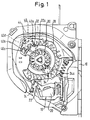
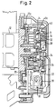
- a belt spool 12 is rotatably mounted between the two legs of a U-shaped housing 10.
- an externally toothed clutch disc 14 to which an externally toothed control disc 16 is rotatably coupled, is connected in a rotationally fixed manner in a conventional manner.
- a vehicle-sensitive trigger mechanism which is pivotably mounted on the housing 10 and is generally designated 18 in the figures, comprises a control pawl 22 resting on a ball 20, which engages with the external toothing of the clutch disc 14 when the ball 20 is moved in a vehicle-sensitive manner.
- the trigger mechanism 18 is pivoted in order to activate a pawl 28 in a known manner, which then engages in an external toothing on the flange 12a of the belt spool and blocks it in a rotationally fixed manner.
- the same blocking process is triggered by means of the webbing sensitive by means of the control disk 16, which, due to its inertia, opposes a rapid rotational acceleration, so that there is a relative rotation between the belt reel 12 and the control disk 16, which is transmitted to the pawl 28 via a clutch pawl 24 and a control lever 26 .
- the belt retractor can be put into the locked state by pulling out a certain length of belt strap. After the belt webbing is almost completely rewound, the belt retractor is switched back to the vehicle- and webbing-sensitive locking mode.
- the belt spool rotation must therefore be implemented in switching strokes, namely a switch-on stroke for switching on the locking mechanism when the webbing is almost completely unwound and a switch-off stroke when the webbing is almost completely rewound.
- a planetary gear transmission which comprises a sun gear 30 non-rotatably connected to the flange 12a of the belt reel 12, an internally toothed ring gear 31 fastened to the housing 10 and two externally toothed planet gears 34, 32 which are offset by 180 ° and which are connected to the Sun gear 30 and the ring gear 31 are in meshing engagement.
- the planet gears 32, 34 each have eight teeth, seven of which are blunt and the eighth is radially extended as a switching tooth 32a or 34a.
- a rocker switch 40 designed as a two-armed lever is pivotably mounted on a pin fixed to the housing and has two actuating arms 40a, 40b, of which the actuating arm 40b is provided with a molded pawl 40c.
- the pawl 40c either engages with an external toothing on the inertia disk 16 or is disengaged from it.
- the pawl 40c engages with the external toothing of the control disk 16
- it holds it in a rotationally fixed manner so that the locking mechanism of the belt retractor is activated in the manner described above by relative rotation between the belt reel 12 and the control disk 16.
- the toothing geometry on the control disk 16 on the one hand and the switching pawl 40c on the other hand is selected such that rotation of the belt retractor in the winding direction is possible.
- the rocker switch 40 carries a cam 40d between its two actuating arms, which cooperates with a spring-loaded pressure piece 44 in order to hold the rocker switch 40 bistably in one of two possible switching positions.
- the ring gear 31 is opposite to the actuating arms 40a, 40b of the rocker switch 40, each with a gap through which the switching teeth 32a and 34a can press the relevant actuating arm of the rocker switch 40 if they are in the appropriate circulation and Rotary position.
- the switching tooth 32a presses the actuating arm 40a of the rocker switch when the planetary gear 32 is suitably rotated and rotated in order to control the switching tooth 40c into the peripheral toothing of the control disk 16; by means of the switching tooth 34a, on the other hand, when the planet gear 34 is in the appropriate rotational and rotational position, the actuating arm 40b of the rocker switch 40 is pressed in order to reset the rocker switch back to its starting position.
- the tooth pitches of the sun gear 30, the ring gear 31 and the planet gears 32, 34 are selected so that after each complete revolution of a planet gear its switching tooth 32a or 34a is offset by the pitch of its toothing.
Landscapes
- Engineering & Computer Science (AREA)
- Mechanical Engineering (AREA)
- Automotive Seat Belt Assembly (AREA)
Claims (3)
- Enrouleur de ceinture pour ceinture de sécurité de véhicule, aveca) une bobine de ceinture (12) montée de façon à pouvoir tourner dans un boîtier (10);b) un mécanisme d'arrêt (28) pour bloquer la rotation de la bobine de la ceinture;c) un mécanisme de libération (18), qui présente un disque de commande (16) qui peut tourner de façon limitée par rapport à la bobine de la ceinture (12), dont la rotation relative par rapport à la bobine de la ceinture (12) peut activer le mécanisme d'arrêt;d) un élément de commande (40), qui peut être inversé entre deux positions stables de commande et qui active dans la première position de commande le mécanisme d'arrêt (28) et libère dans la seconde position le mécanisme d'arrêt;e) une boîte à engrenages planétaires avec une roue solaire (30) raccordée de façon solidaire en rotation à la bobine de la ceinture (12), une roue creuse (31) solidaire du boîtier et au moins une roue planétaire (32, 34), qui présente une denture externe et est en prise avec la roue solaire (30) et la roue creuse (31);caractérisé en ce que l'élément de commande est constitué sous la forme d'une bascule de commande (40) montée de façon à pouvoir pivoter, bascule qui présente deux bras d'actionnement (40a, 40b) et un cliquet de commande (40c), qui vient en prise dans la première position de commande sur le disque de commande (16) et l'empêche de tourner et en ce que la denture externe de la roue planétaire (32, 34) comprend au moins une dent de commande (32a, 34a) plus longue dans le sens radial qui arrive directement en prise dans une position déterminée de révolution et de rotation de la roue planétaire (32, 34) avec l'un des bras d'actionnement de la bascule de commande (40) et met la bascule de commande (40) dans son autre position de commande.
- Enrouleur de ceinture selon la revendication 1, caractérisé en ce que l'on prévoit deux roues planétaires (32, 34), disposées de façon décalée l'une par rapport à l'autre dans le sens périphérique avec chacune une dent de commande (32a, 34a), dont la première (32) vient en prise, dans une position déterminée de révolution et de rotation, avec l'un des bras d'actionnement (40a) de la bascule de commande (40) et la seconde (34), dans une autre position de rotation et de révolution, avec l'autre bras d'actionnement (40b) de la bascule de commande (40).
- Enrouleur de ceinture selon la revendication 1 ou 2, caractérisé en ce que la position de rotation de la dent de commande (32a, 34a) sur la roue planétaire (32, 34) est décalée après chaque révolution complète d'une division de sa denture ou d'un multiple de cette division.
Applications Claiming Priority (2)
| Application Number | Priority Date | Filing Date | Title |
|---|---|---|---|
| DE9318286U DE9318286U1 (de) | 1993-11-30 | 1993-11-30 | Gurtaufroller für Fahrzeugsicherheitsgurte |
| DE9318286U | 1993-11-30 |
Publications (2)
| Publication Number | Publication Date |
|---|---|
| EP0655372A1 EP0655372A1 (fr) | 1995-05-31 |
| EP0655372B1 true EP0655372B1 (fr) | 1997-01-29 |
Family
ID=6901313
Family Applications (1)
| Application Number | Title | Priority Date | Filing Date |
|---|---|---|---|
| EP94118194A Expired - Lifetime EP0655372B1 (fr) | 1993-11-30 | 1994-11-18 | Rétracteur de sangle pour ceintures de sécurité de véhicule |
Country Status (5)
| Country | Link |
|---|---|
| US (1) | US5474247A (fr) |
| EP (1) | EP0655372B1 (fr) |
| JP (1) | JP2634382B2 (fr) |
| DE (2) | DE9318286U1 (fr) |
| ES (1) | ES2076912T3 (fr) |
Families Citing this family (15)
| Publication number | Priority date | Publication date | Assignee | Title |
|---|---|---|---|---|
| US5601251A (en) * | 1995-03-31 | 1997-02-11 | Trw Vehicle Safety Systems Inc. | Adjustable automatic locking retractor |
| DE29520425U1 (de) * | 1995-12-22 | 1996-04-25 | Trw Occupant Restraint Systems Gmbh, 73551 Alfdorf | Gurtaufroller für Fahrzeugsicherheitsgurte |
| DE29608209U1 (de) * | 1996-05-06 | 1996-09-05 | Trw Occupant Restraint Systems Gmbh, 73551 Alfdorf | Gurtaufroller für Fahrzeugsicherheitsgurte |
| JP3204911B2 (ja) * | 1996-11-06 | 2001-09-04 | 株式会社東海理化電機製作所 | ウエビング巻取装置 |
| DE29702610U1 (de) * | 1997-02-14 | 1997-06-12 | Trw Occupant Restraint Systems Gmbh, 73551 Alfdorf | Gurtaufroller für einen Fahrzeugsicherheitsgurt |
| DE19732454C2 (de) * | 1997-07-29 | 2002-02-21 | Autoliv Dev | Selbstsperrender Gurtaufroller mit Retractor-Umschaltung |
| DE20019468U1 (de) * | 2000-11-16 | 2001-03-29 | TRW Occupant Restraint Systems GmbH & Co. KG, 73553 Alfdorf | Gurtaufroller für einen Fahrzeug-Sicherheitsgurt |
| EP1291437A1 (fr) * | 2001-09-05 | 2003-03-12 | Bayer Ag | Nouveau système de détection d'inhibiteurs d'hélicases |
| DE10358561A1 (de) * | 2003-12-15 | 2005-08-04 | Trw Occupant Restraint Systems Gmbh & Co. Kg | Gurtaufroller für einen Fahrzeug-Sicherheitsgurt |
| US7387076B2 (en) * | 2005-04-08 | 2008-06-17 | Merritt Industies, Inc. | Locking system for a door of an enclosure |
| JP4919895B2 (ja) * | 2007-07-20 | 2012-04-18 | 本田技研工業株式会社 | 車両のシートベルト装置およびその制御方法 |
| JP5912777B2 (ja) | 2012-03-30 | 2016-04-27 | 株式会社東海理化電機製作所 | ウェビング巻取装置 |
| JP5797598B2 (ja) * | 2012-04-06 | 2015-10-21 | 株式会社東海理化電機製作所 | ウェビング巻取装置及びその組立方法 |
| EP3127761B1 (fr) * | 2015-08-01 | 2017-07-05 | TRW Automotive GmbH | Enrouleur de ceinture pour une ceinture de securite de vehicule |
| EP3127760B1 (fr) * | 2015-08-01 | 2017-11-08 | TRW Automotive GmbH | Enrouleur de ceinture pour une ceinture de securite de vehicule |
Family Cites Families (10)
| Publication number | Priority date | Publication date | Assignee | Title |
|---|---|---|---|---|
| JPS5976252U (ja) * | 1982-11-15 | 1984-05-23 | 株式会社東海理化電機製作所 | ウエビング巻取装置 |
| JPS6238528A (ja) * | 1985-08-13 | 1987-02-19 | Hitachi Maxell Ltd | 磁気記録媒体 |
| JPS6247462U (fr) * | 1985-09-13 | 1987-03-24 | ||
| US4726539A (en) * | 1985-10-16 | 1988-02-23 | General Safety Corporation | Dual mode seat belt retractor assembly |
| JPS6274063U (fr) * | 1985-10-30 | 1987-05-12 | ||
| US4809926A (en) * | 1986-06-21 | 1989-03-07 | Nippon Seiko Kabushiki Kaisha | Webbing retractor |
| US4729524A (en) * | 1986-09-26 | 1988-03-08 | Trw Vehicle Safety Systems Limited | Seat belt retractor with cinch mechanism |
| JPH0818533B2 (ja) * | 1986-12-12 | 1996-02-28 | 芦森工業株式会社 | シ−トベルトのリトラクタ− |
| JPS63145747U (fr) * | 1987-03-18 | 1988-09-26 | ||
| US4915321A (en) * | 1988-09-20 | 1990-04-10 | Trw Vehicle Safety Systems Inc. | Retractor with cinch mechanism |
-
1993
- 1993-11-30 DE DE9318286U patent/DE9318286U1/de not_active Expired - Lifetime
-
1994
- 1994-11-18 ES ES94118194T patent/ES2076912T3/es not_active Expired - Lifetime
- 1994-11-18 DE DE59401712T patent/DE59401712D1/de not_active Expired - Fee Related
- 1994-11-18 EP EP94118194A patent/EP0655372B1/fr not_active Expired - Lifetime
- 1994-11-23 US US08/344,460 patent/US5474247A/en not_active Expired - Lifetime
- 1994-11-29 JP JP6295183A patent/JP2634382B2/ja not_active Expired - Fee Related
Also Published As
| Publication number | Publication date |
|---|---|
| DE59401712D1 (de) | 1997-03-13 |
| EP0655372A1 (fr) | 1995-05-31 |
| ES2076912T1 (es) | 1995-11-16 |
| JP2634382B2 (ja) | 1997-07-23 |
| JPH07277137A (ja) | 1995-10-24 |
| ES2076912T3 (es) | 1997-06-01 |
| US5474247A (en) | 1995-12-12 |
| DE9318286U1 (de) | 1994-02-03 |
Similar Documents
| Publication | Publication Date | Title |
|---|---|---|
| EP0655372B1 (fr) | Rétracteur de sangle pour ceintures de sécurité de véhicule | |
| EP0806326B1 (fr) | Rétracteur pour ceintures de sécurité de véhicule automobile | |
| DE3342478C2 (de) | Gurtaufroller | |
| DE102012019004B4 (de) | Gurtaufroller für einen Sicherheitsgurt | |
| DE2851650C2 (de) | Aufrollvorrichtung mit Zugentlastung für Sicherheitgurte | |
| DE10213906A1 (de) | Leistungsstraffer | |
| DE60213478T2 (de) | Sicherheitsgurtaufroller | |
| EP0743221A2 (fr) | Mécanisme de réglage pour sièges de véhicules automobiles | |
| DE19648515A1 (de) | Sicherheitsgurtvorrichtung für Kraftfahrzeuge | |
| DE4132876C2 (fr) | ||
| EP0560176B1 (fr) | Système de retenue à ceinture de sécurité pour véhicules | |
| DE102012000760B4 (de) | Gurtaufroller mit Rücklaufbremse | |
| DE29820086U1 (de) | Gurtaufroller für einen Fahrzeug-Sicherheitsgurt | |
| DE19541430C2 (de) | Elektrisch gesteuerter Sicherheitsgurtaufroller | |
| DE3509254C2 (fr) | ||
| DE2547119C3 (de) | Selbstsperrender Gurtaufroller für Sicherheitsgurte | |
| EP0858936B1 (fr) | Enrouleur pour une ceinture de sécurité de véhicule | |
| EP0543044B1 (fr) | Rétracteur de sangle avec soulagement de traction pour systèmes de retenue par ceinture de sécurité pour véhicules | |
| DE19544918A1 (de) | Sicherheitsgurtaufroller | |
| EP0568820B1 (fr) | Enrouleur de ceinture à réduction de tension pour systèmes de retenue à ceinture de sécurité pour véhicules | |
| DE4444655C2 (de) | Sicherheitsgurt-Blockiereinrichtung mit Selbstblockadeverhinderung | |
| DE19539284C2 (de) | Selbstsperrender Gurtaufroller mit Retractor-Umschaltung | |
| DE19602178C1 (de) | Elektrisch gesteuerter Sicherheitsgurtaufroller mit Stromsparschaltung | |
| EP0780270A1 (fr) | Enrouleur de ceintures de sécurité pour véhicule | |
| DE3103993A1 (de) | Sicherheitsgurteinzieheinrichtung mit einer zugentlastungseinrichtung |
Legal Events
| Date | Code | Title | Description |
|---|---|---|---|
| PUAI | Public reference made under article 153(3) epc to a published international application that has entered the european phase |
Free format text: ORIGINAL CODE: 0009012 |
|
| AK | Designated contracting states |
Kind code of ref document: A1 Designated state(s): DE ES FR GB IT SE |
|
| ITCL | It: translation for ep claims filed |
Representative=s name: DR. ING. A. RACHELI & C. |
|
| GBC | Gb: translation of claims filed (gb section 78(7)/1977) | ||
| EL | Fr: translation of claims filed | ||
| 17P | Request for examination filed |
Effective date: 19950718 |
|
| REG | Reference to a national code |
Ref country code: ES Ref legal event code: BA2A Ref document number: 2076912 Country of ref document: ES Kind code of ref document: T1 |
|
| RAP1 | Party data changed (applicant data changed or rights of an application transferred) |
Owner name: TRW OCCUPANT RESTRAINT SYSTEMS GMBH |
|
| GRAG | Despatch of communication of intention to grant |
Free format text: ORIGINAL CODE: EPIDOS AGRA |
|
| GRAH | Despatch of communication of intention to grant a patent |
Free format text: ORIGINAL CODE: EPIDOS IGRA |
|
| 17Q | First examination report despatched |
Effective date: 19960614 |
|
| GRAH | Despatch of communication of intention to grant a patent |
Free format text: ORIGINAL CODE: EPIDOS IGRA |
|
| GRAA | (expected) grant |
Free format text: ORIGINAL CODE: 0009210 |
|
| AK | Designated contracting states |
Kind code of ref document: B1 Designated state(s): DE ES FR GB IT SE |
|
| ITF | It: translation for a ep patent filed | ||
| GBT | Gb: translation of ep patent filed (gb section 77(6)(a)/1977) |
Effective date: 19970212 |
|
| REF | Corresponds to: |
Ref document number: 59401712 Country of ref document: DE Date of ref document: 19970313 |
|
| ET | Fr: translation filed | ||
| REG | Reference to a national code |
Ref country code: ES Ref legal event code: FG2A Ref document number: 2076912 Country of ref document: ES Kind code of ref document: T3 |
|
| PG25 | Lapsed in a contracting state [announced via postgrant information from national office to epo] |
Ref country code: SE Free format text: LAPSE BECAUSE OF NON-PAYMENT OF DUE FEES Effective date: 19971119 |
|
| PLBE | No opposition filed within time limit |
Free format text: ORIGINAL CODE: 0009261 |
|
| STAA | Information on the status of an ep patent application or granted ep patent |
Free format text: STATUS: NO OPPOSITION FILED WITHIN TIME LIMIT |
|
| 26N | No opposition filed | ||
| EUG | Se: european patent has lapsed |
Ref document number: 94118194.3 |
|
| REG | Reference to a national code |
Ref country code: GB Ref legal event code: IF02 |
|
| PGFP | Annual fee paid to national office [announced via postgrant information from national office to epo] |
Ref country code: GB Payment date: 20021002 Year of fee payment: 9 |
|
| PG25 | Lapsed in a contracting state [announced via postgrant information from national office to epo] |
Ref country code: GB Free format text: LAPSE BECAUSE OF NON-PAYMENT OF DUE FEES Effective date: 20031118 |
|
| GBPC | Gb: european patent ceased through non-payment of renewal fee |
Effective date: 20031118 |
|
| PGFP | Annual fee paid to national office [announced via postgrant information from national office to epo] |
Ref country code: ES Payment date: 20041119 Year of fee payment: 11 |
|
| PG25 | Lapsed in a contracting state [announced via postgrant information from national office to epo] |
Ref country code: ES Free format text: LAPSE BECAUSE OF NON-PAYMENT OF DUE FEES Effective date: 20051119 |
|
| REG | Reference to a national code |
Ref country code: ES Ref legal event code: FD2A Effective date: 20051119 |
|
| PGFP | Annual fee paid to national office [announced via postgrant information from national office to epo] |
Ref country code: IT Payment date: 20071120 Year of fee payment: 14 |
|
| PGFP | Annual fee paid to national office [announced via postgrant information from national office to epo] |
Ref country code: FR Payment date: 20071105 Year of fee payment: 14 |
|
| PGFP | Annual fee paid to national office [announced via postgrant information from national office to epo] |
Ref country code: DE Payment date: 20081128 Year of fee payment: 15 |
|
| PG25 | Lapsed in a contracting state [announced via postgrant information from national office to epo] |
Ref country code: IT Free format text: LAPSE BECAUSE OF NON-PAYMENT OF DUE FEES Effective date: 20081118 |
|
| REG | Reference to a national code |
Ref country code: FR Ref legal event code: ST Effective date: 20090731 |
|
| PG25 | Lapsed in a contracting state [announced via postgrant information from national office to epo] |
Ref country code: DE Free format text: LAPSE BECAUSE OF NON-PAYMENT OF DUE FEES Effective date: 20100601 |
|
| PG25 | Lapsed in a contracting state [announced via postgrant information from national office to epo] |
Ref country code: FR Free format text: LAPSE BECAUSE OF NON-PAYMENT OF DUE FEES Effective date: 20081130 |