EP0655558A1 - Soupape pneumatique avec au moins deux modules fixés l'un à l'autre - Google Patents
Soupape pneumatique avec au moins deux modules fixés l'un à l'autre Download PDFInfo
- Publication number
- EP0655558A1 EP0655558A1 EP94116969A EP94116969A EP0655558A1 EP 0655558 A1 EP0655558 A1 EP 0655558A1 EP 94116969 A EP94116969 A EP 94116969A EP 94116969 A EP94116969 A EP 94116969A EP 0655558 A1 EP0655558 A1 EP 0655558A1
- Authority
- EP
- European Patent Office
- Prior art keywords
- valve device
- pneumatic valve
- housing
- housing modules
- bolts
- Prior art date
- Legal status (The legal status is an assumption and is not a legal conclusion. Google has not performed a legal analysis and makes no representation as to the accuracy of the status listed.)
- Granted
Links
Images
Classifications
-
- F—MECHANICAL ENGINEERING; LIGHTING; HEATING; WEAPONS; BLASTING
- F15—FLUID-PRESSURE ACTUATORS; HYDRAULICS OR PNEUMATICS IN GENERAL
- F15B—SYSTEMS ACTING BY MEANS OF FLUIDS IN GENERAL; FLUID-PRESSURE ACTUATORS, e.g. SERVOMOTORS; DETAILS OF FLUID-PRESSURE SYSTEMS, NOT OTHERWISE PROVIDED FOR
- F15B13/00—Details of servomotor systems ; Valves for servomotor systems
- F15B13/02—Fluid distribution or supply devices characterised by their adaptation to the control of servomotors
- F15B13/06—Fluid distribution or supply devices characterised by their adaptation to the control of servomotors for use with two or more servomotors
- F15B13/08—Assemblies of units, each for the control of a single servomotor only
- F15B13/0803—Modular units
- F15B13/0807—Manifolds
- F15B13/0814—Monoblock manifolds
-
- F—MECHANICAL ENGINEERING; LIGHTING; HEATING; WEAPONS; BLASTING
- F15—FLUID-PRESSURE ACTUATORS; HYDRAULICS OR PNEUMATICS IN GENERAL
- F15B—SYSTEMS ACTING BY MEANS OF FLUIDS IN GENERAL; FLUID-PRESSURE ACTUATORS, e.g. SERVOMOTORS; DETAILS OF FLUID-PRESSURE SYSTEMS, NOT OTHERWISE PROVIDED FOR
- F15B13/00—Details of servomotor systems ; Valves for servomotor systems
- F15B13/02—Fluid distribution or supply devices characterised by their adaptation to the control of servomotors
- F15B13/06—Fluid distribution or supply devices characterised by their adaptation to the control of servomotors for use with two or more servomotors
- F15B13/08—Assemblies of units, each for the control of a single servomotor only
- F15B13/0803—Modular units
- F15B13/0821—Attachment or sealing of modular units to each other
-
- F—MECHANICAL ENGINEERING; LIGHTING; HEATING; WEAPONS; BLASTING
- F15—FLUID-PRESSURE ACTUATORS; HYDRAULICS OR PNEUMATICS IN GENERAL
- F15B—SYSTEMS ACTING BY MEANS OF FLUIDS IN GENERAL; FLUID-PRESSURE ACTUATORS, e.g. SERVOMOTORS; DETAILS OF FLUID-PRESSURE SYSTEMS, NOT OTHERWISE PROVIDED FOR
- F15B13/00—Details of servomotor systems ; Valves for servomotor systems
- F15B13/02—Fluid distribution or supply devices characterised by their adaptation to the control of servomotors
- F15B13/06—Fluid distribution or supply devices characterised by their adaptation to the control of servomotors for use with two or more servomotors
- F15B13/08—Assemblies of units, each for the control of a single servomotor only
- F15B13/0803—Modular units
- F15B13/0846—Electrical details
- F15B13/0857—Electrical connecting means, e.g. plugs, sockets
Definitions
- the invention is based on a pneumatic valve device with at least two housing modules fastened to one another according to the type specified in the preamble of claim 1.
- Such a pneumatic valve device is already known from WO 92/04568, in which a plurality of housing modules of the same construction are flanged to avoid individual pressure medium lines, the desired pressure medium connections being produced in the parting plane between two flange surfaces by plugs and tubular couplings, which in the channel openings of the housing modules are used.
- the tubular couplings essentially only take on the function of the pressure medium feed-through and the seal from the outside.
- a pin-hole arrangement is additionally provided for centering two housing modules with respect to one another.
- each housing module has a protruding fastening foot and one to it on two opposite flange surfaces of a cuboid housing has a suitable recess for receiving the mounting foot of the adjacent housing module.
- Such screw connections build complex, expensive and take up a lot of space, which is not available especially with small valves.
- valve device with housing modules fastened to one another is known, which are designed as pilot valve and main control valve.
- a tubular bolt lying in the parting plane takes over the functions of the pressure medium connection and the centering.
- this valve device only a single pin is provided, which uses additional O-rings for the sealing and which has a collar on the outside for its axial adjustment.
- This valve device works with a hydraulic medium and is designed for high pressures, which is why the housing modules are held together by screw connections, which are correspondingly complex and expensive.
- the cuboid housing module for receiving several valve axes is made of plastic, the housing module carrying on one long side a metallic connection plate to which the pressure medium lines can be attached.
- the connection plate itself can be fastened to the housing module by screwing or gluing, alternatively a detachable holder is provided, wherein sleeve-shaped bolts made of rubber-like material are inserted into the two components in the region of a parting plane.
- Each bolt has an outer collar for sealing in the parting plane.
- each half of the bolt has an external annular bead which is semi-annular in cross section and which fits into the corresponding Ring grooves can be tied into the channels of both components.
- the main disadvantage is that the rubber-like bolts cannot transmit greater mechanical forces and therefore the metallic connecting plate is sunk in a suitable groove in the housing module. Furthermore, the channels for receiving the semicircular ring beads must be machined in an expensive manner. Furthermore, only a detachable plug connection can be achieved here, which is not desired in many cases. In addition, the flexible bolts make quick and easy assembly difficult.
- the pneumatic valve device according to the invention with at least two housing modules attached to one another with the characterizing features of claim 1 has the advantage that it enables a compact and inexpensive plug connection between the housing modules with a simple design.
- the plug-in connection by means of hollow bolts is particularly space-saving, since additional screws as holding members are omitted and the functions of centering, sealing and holding are concentrated in the smallest space. Because the screws are omitted, there are no dirt corners in the area of the screw heads.
- O-rings can be dispensed with, since the ring beads themselves take over the sealing with their cutting edge. When the bolts are mounted, their cutting edges can cling to the housing modules so strongly that a secure and firm connection between the two housing modules is achieved.
- This plug connection is therefore particularly suitable for small-sized valves, especially if a pilot valve is attached to a directional control valve on the front. It is particularly favorable if the bolts are made of steel for a pilot valve with a plastic housing and for a main control valve with an aluminum housing in order to ensure a safe, tight and permanent connection. Furthermore, it is expedient if, in the case of particularly high demands on the tightness and the mounting between two housing modules, a bolt is used in which the cutting edges are arranged twice.
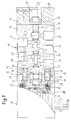
- FIG. 1 shows a longitudinal section through a pneumatic Valve device with the plug connection according to the invention in a simplified representation
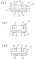
- FIG. 2 the pin according to FIG. 1 on an enlarged scale
- FIGS. 3 and 4 a second or third embodiment of the pin for the plug connection according to FIG. 1.
- FIG. 1 shows a simplified representation of a longitudinal section through a pneumatic valve device with at least two housing modules fastened to one another, the valve device itself being designed as an electromagnetically pilot-operated 5/2-way valve 10, its main control valve 11 and its associated pilot valve 12 forming the two housing modules.
- Both housing modules 11, 12 abut with one another with their end flange surfaces 13 and 14 in a parting plane 15 and are permanently connected to one another by a plug connection 16.
- the main control valve 11 is designed in a manner known per se as a 5/2 control valve, the housing 17 of which has a cuboid shape and accommodates a longitudinally movable control slide 19 in a continuous slide bore 18.
- the control slide 19 controls in the usual way the connection between an inlet connection 21, two motor connections 22, 23 and two return connections 24, 25, for which purpose it can be deflected in two working positions.
- Two actuating pistons 26, 27 are provided for actuating the control slide 19, of which the first actuating piston 26 is slidably guided in a housing 28 of the pilot valve 12.
- the second actuating piston 27 is slidably arranged in a cover 29, which is opposite to the pilot valve 12 on the front flange surface 31 of the Main control valve 11 is attached.
- Both actuating pistons 26, 27 are each assigned a pressure chamber 32 or 33, which can be controlled via two solenoid valves 34, 25.
- Both solenoid valves 34, 35 are arranged one above the other in the housing 28 of the pilot valve 12 in the plane of the drawing and are each designed as a 3/2-way valve which can be controlled via the electrical connection 36.
- the two solenoid valves 34, 35 in the pilot valve 12 are supplied with pressure medium via a first control channel 37, which runs in the housing 17 of the main control valve 11 from the inlet connection 21 into the lower half of the flange surface 13, penetrates the parting plane 15 and closes in the housing 28 of the pilot valve 12 leads to the inlet connections of the solenoid valves 34, 35.
- a control connection of the first solenoid valve 34 is connected to the pressure chamber 32 on the first actuating piston 26.
- a control connection of the second solenoid valve 35 has a second control channel 38 with the pressure chamber 33 on the second actuating piston 27, the second control channel 38 from the housing 28 of the pilot valve 12 through the flange surfaces 13, 14 in the housing 17 of the main valve 11 and further on Cover 29 extends into the pressure chamber 33.
- the drain connections of the solenoid valves 34, 35 are connected to the return connection 24 in a manner not shown.
- the two control channels 37, 38 are each guided by a hollow bolt 41 and 42, which form parts of the plug connection 16.
- the two bolts 41, 42 are identical to one another and are made of steel.
- Such a bolt 41 is shown in FIG. 2 on an enlarged scale, to which reference is made in the following.
- the bolt 41 essentially consists of a tubular sleeve 43, the through bore 44 of which has approximately the diameter of a control channel 37 or 38.
- two annular beads 45, 46 are arranged at a distance from each other, each of which consists of a conical chamfer 47 which ends in a cutting edge 48.
- the tapered chamfers 47 are arranged in the two halves of the bolt 41 in such a way that their diameter increases counter to the direction of insertion; thus the two cutting edges 48 face each other.
- the two ends are provided with bevels 49 for easier insertion of the bolts 41.
- the distance between the annular beads 45, 46 from one another is approximately as large as the outside diameter of the sleeve 43, so that a sufficiently large cylindrical surface area remains for guiding tasks.
- the bolt 41 is thus rotationally symmetrical to its longitudinal axis 51 and can be easily manufactured as a turned part; in addition, it is symmetrical to a central transverse plane 52, which facilitates its handling during assembly.
- blind-hole-like receiving bores 53 to 56 are arranged in the housing 17 of the control valve 11 and in the housing 28 of the pilot valve 12, each starting from the flange surfaces 13 and 14 and lying in the control channels 37 and 38.
- These receiving bores 53 to 56 are all of the same diameter and their axial length corresponds to half the length of the bolt 41 or 42.
- the bolts 41, 42 can therefore be inserted into the receiving bores 53, 54 as far as they will go.
- the outer diameter of the bolts 41, 42 and the inner diameter of the receiving bores 53 to 56 are coordinated with one another such that, on the one hand, the two housing modules 11, 12 are precisely centered and guided with respect to one another and, on the other hand, the annular beads 45, 46 with their cutting edges 48 are in such a way claws the housings 28 and 17, respectively, that the plug connection 16 is an inseparable, secure and firm mounting of both housing modules 11, 12 results in each other.
- a kind of pine cone connection is produced.
- By clawing the annular beads 45, 46 in the two housing modules 11, 12, a secure sealing of the pressure medium-carrying control channels 37, 38 is simultaneously effected to the outside.
- This connector 16 has the advantage that the bolts 41, 42 are made of a harder material than that of the housing 17 and 28.
- the housing 17 of the main control valve 11 is made of aluminum, while the housing 28 of the pilot valve 12 is made of plastic consists.
- the plug connection 16 is extremely space-saving, with a multitude of functions being integrated in a confined space, namely in particular the centering of the two housing modules 11, 12 relative to one another, the implementation pressure medium channels through a parting plane 15, the sealing of pressure medium channels to the outside and above all the mechanical mounting of both housings 17, 28 to each other.
- the advantage here is that the connector 16 can exert such holding forces that the arrangement of pressurized actuating pistons in the housing 28 of the pilot valve 12 is possible. Due to the large number of integrated functions, this connector is particularly suitable for small valves.
- the plug connection 16 can therefore expediently be used in valve devices 10 in which the housings 17, 28 each have an approximately equal rectangular housing cross section, the thickness of the housing 17 or 28 being only slightly larger than the outer diameter of an actuating piston 26, 27.
- a pilot valve with two solenoid valves 34, 35 arranged one above the other can thereby be attached to the main control valve 11 in a particularly expedient and simple manner, the plug connection 16 establishing an inseparable connection and thus preventing an unwanted dismantling of the pilot valve 12.
- FIG. 3 shows a second embodiment of a bolt 60, which differs from the bolt 41 according to FIG. 2 only in that each annular bead 45, 46 is assigned a second annular bead 61 which carries an additional cutting edge 62.
- the double arrangement of cutting edges 48, 62 makes it possible to meet higher tightness requirements in special cases.
- FIG. 4 shows a bolt 65 which differs from the bolt 41 according to FIG. 2 only in that the annular beads 45, 46 now have a trapezoidal cross section.
- the stability of the cutting edge 48 can be increased for special purposes and the safety of the holding function can be increased.
- Fig. 1 shown application of the connector 16 in a 5/2-way valve in longitudinal slide type is particularly useful, the connector can be carried out with three or more bolts if necessary. It is also possible to provide such a plug connection for fastening the cover 29. The plug connection can also be used very generally in other housing modules in which there are comparable conditions.
Landscapes
- Engineering & Computer Science (AREA)
- Physics & Mathematics (AREA)
- Fluid Mechanics (AREA)
- Mechanical Engineering (AREA)
- General Engineering & Computer Science (AREA)
- Valve Housings (AREA)
Applications Claiming Priority (2)
| Application Number | Priority Date | Filing Date | Title |
|---|---|---|---|
| DE4340770A DE4340770A1 (de) | 1993-11-30 | 1993-11-30 | Pneumatische Ventileinrichtung mit wenigstens zwei aneinander befestigten Gehäusemodulen |
| DE4340770 | 1993-11-30 |
Publications (2)
| Publication Number | Publication Date |
|---|---|
| EP0655558A1 true EP0655558A1 (fr) | 1995-05-31 |
| EP0655558B1 EP0655558B1 (fr) | 1998-07-08 |
Family
ID=6503797
Family Applications (1)
| Application Number | Title | Priority Date | Filing Date |
|---|---|---|---|
| EP94116969A Expired - Lifetime EP0655558B1 (fr) | 1993-11-30 | 1994-10-27 | Soupape pneumatique avec au moins deux modules fixés l'un à l'autre |
Country Status (3)
| Country | Link |
|---|---|
| EP (1) | EP0655558B1 (fr) |
| DE (2) | DE4340770A1 (fr) |
| ES (1) | ES2118297T3 (fr) |
Cited By (2)
| Publication number | Priority date | Publication date | Assignee | Title |
|---|---|---|---|---|
| CN109764161A (zh) * | 2019-01-25 | 2019-05-17 | 鼎斯(上海)液压科技有限公司 | 片式组合滑阀系统及组合方法 |
| EP4083483A1 (fr) * | 2021-04-29 | 2022-11-02 | Georg Fischer Rohrleitungssysteme AG | Soupape de régulation de pression |
Families Citing this family (2)
| Publication number | Priority date | Publication date | Assignee | Title |
|---|---|---|---|---|
| DE19623446A1 (de) | 1996-06-12 | 1997-12-18 | Bosch Gmbh Robert | Elektropneumatisch vorgesteuertes Wegeventil |
| DE102006024762B4 (de) * | 2006-05-27 | 2010-12-02 | Festo Ag & Co. Kg | Ventil |
Citations (5)
| Publication number | Priority date | Publication date | Assignee | Title |
|---|---|---|---|---|
| DE1031595B (de) * | 1953-10-30 | 1958-06-04 | Erich Herion | Ventile in Batterieanordnung mit verbindenden Zwischengliedern fuer die Weiterleitung des Mediums |
| US3234963A (en) * | 1962-11-28 | 1966-02-15 | Thomas E Lyon | Manifold assembly |
| DE2310698A1 (de) * | 1972-06-15 | 1973-12-20 | Westinghouse Brake & Signal | Ventilbatterie |
| DE2701598C2 (de) * | 1977-01-15 | 1985-03-21 | Mannesmann Rexroth GmbH, 8770 Lohr | Vorgesteuertes Hochdruck-Sitzventil |
| GB2178139A (en) * | 1985-06-27 | 1987-02-04 | Festo Kg | A valve housing arrangement |
Family Cites Families (1)
| Publication number | Priority date | Publication date | Assignee | Title |
|---|---|---|---|---|
| AU8635791A (en) * | 1990-09-05 | 1992-03-30 | Newmatic Controls Inc. | Modular pneumatic control systems |
-
1993
- 1993-11-30 DE DE4340770A patent/DE4340770A1/de not_active Withdrawn
-
1994
- 1994-10-27 ES ES94116969T patent/ES2118297T3/es not_active Expired - Lifetime
- 1994-10-27 DE DE59406408T patent/DE59406408D1/de not_active Expired - Lifetime
- 1994-10-27 EP EP94116969A patent/EP0655558B1/fr not_active Expired - Lifetime
Patent Citations (5)
| Publication number | Priority date | Publication date | Assignee | Title |
|---|---|---|---|---|
| DE1031595B (de) * | 1953-10-30 | 1958-06-04 | Erich Herion | Ventile in Batterieanordnung mit verbindenden Zwischengliedern fuer die Weiterleitung des Mediums |
| US3234963A (en) * | 1962-11-28 | 1966-02-15 | Thomas E Lyon | Manifold assembly |
| DE2310698A1 (de) * | 1972-06-15 | 1973-12-20 | Westinghouse Brake & Signal | Ventilbatterie |
| DE2701598C2 (de) * | 1977-01-15 | 1985-03-21 | Mannesmann Rexroth GmbH, 8770 Lohr | Vorgesteuertes Hochdruck-Sitzventil |
| GB2178139A (en) * | 1985-06-27 | 1987-02-04 | Festo Kg | A valve housing arrangement |
Cited By (4)
| Publication number | Priority date | Publication date | Assignee | Title |
|---|---|---|---|---|
| CN109764161A (zh) * | 2019-01-25 | 2019-05-17 | 鼎斯(上海)液压科技有限公司 | 片式组合滑阀系统及组合方法 |
| EP4083483A1 (fr) * | 2021-04-29 | 2022-11-02 | Georg Fischer Rohrleitungssysteme AG | Soupape de régulation de pression |
| WO2022228825A1 (fr) * | 2021-04-29 | 2022-11-03 | Georg Fischer Rohrleitungssysteme Ag | Soupape de régulation de pression |
| US12292128B2 (en) | 2021-04-29 | 2025-05-06 | Georg Fischer Rohrleitungssysteme Ag | Pressure control valve |
Also Published As
| Publication number | Publication date |
|---|---|
| DE4340770A1 (de) | 1995-06-01 |
| ES2118297T3 (es) | 1998-09-16 |
| DE59406408D1 (de) | 1998-08-13 |
| EP0655558B1 (fr) | 1998-07-08 |
Similar Documents
| Publication | Publication Date | Title |
|---|---|---|
| DE2011409C3 (de) | Ventilschnellkupplung fur zwei gas- oder flussigkeitsfuhrende Leitungen | |
| DE3306526C2 (fr) | ||
| DE19537482A1 (de) | Hydraulischer Steuerblock | |
| WO2007131557A1 (fr) | Rail de tension ou de guidage avec sécurité antiperte pour boulon de retenue | |
| DE102013009650A1 (de) | Ventil | |
| DE4307990A1 (de) | Hydraulisches Steuerventil | |
| DE8524633U1 (de) | Luftfeder mit pneumatischen Anschluß | |
| DE4213732A1 (de) | Verschlußstück zum Abschließen von Druckmittel führenden Bohrungen | |
| DE68928099T2 (de) | Kompakte fluidbetriebene vorrichtung und verfahren | |
| DE10125991A1 (de) | Drehdurchführung für Fuidsysteme | |
| EP0655558B1 (fr) | Soupape pneumatique avec au moins deux modules fixés l'un à l'autre | |
| DE112016004702B4 (de) | Fluiddruckvorrichtung und Verfahren zu deren Herstellung | |
| DE3203533A1 (de) | Hydraulisches einbauventil | |
| EP0667458B1 (fr) | Unité de soupape à aimant proportionnel | |
| EP0519185B1 (fr) | Vérin commandé par un fluide sous pression | |
| DE19802289A1 (de) | Wegeventil | |
| DE2628591C3 (de) | Brennstoffeinspritzpumpe für Brennkraftmaschinen | |
| DE10034935C2 (de) | Mehrwegeventil | |
| DE19929897C2 (de) | Verschlussstruktur für Stellglieder | |
| DE19812044C1 (de) | Gewindeeinsatz | |
| DE2727491A1 (de) | Elektromagnetisches druckregelventil | |
| DE2438865A1 (de) | Aus zylinder und kolben bestehendes steuerventilsystem | |
| EP3101318A1 (fr) | Module de vanne | |
| DE2345964A1 (de) | Anschlussvorrichtung fuer die festen elemente eines hydraulischen kreislaufes | |
| DE2055624C3 (de) | Hydraulische Schaltungsanordnung mit einem Rückschlagventil für ein an eine Flanschfläche eines Montageblockes anflanschbares hydraulisches Arbeitsoder Steuergerät mit mindestens zwei Tankanschlüssen |
Legal Events
| Date | Code | Title | Description |
|---|---|---|---|
| PUAI | Public reference made under article 153(3) epc to a published international application that has entered the european phase |
Free format text: ORIGINAL CODE: 0009012 |
|
| AK | Designated contracting states |
Kind code of ref document: A1 Designated state(s): DE ES FR GB IT |
|
| 17P | Request for examination filed |
Effective date: 19951130 |
|
| 17Q | First examination report despatched |
Effective date: 19961203 |
|
| GRAG | Despatch of communication of intention to grant |
Free format text: ORIGINAL CODE: EPIDOS AGRA |
|
| GRAG | Despatch of communication of intention to grant |
Free format text: ORIGINAL CODE: EPIDOS AGRA |
|
| GRAH | Despatch of communication of intention to grant a patent |
Free format text: ORIGINAL CODE: EPIDOS IGRA |
|
| GRAH | Despatch of communication of intention to grant a patent |
Free format text: ORIGINAL CODE: EPIDOS IGRA |
|
| GRAA | (expected) grant |
Free format text: ORIGINAL CODE: 0009210 |
|
| AK | Designated contracting states |
Kind code of ref document: B1 Designated state(s): DE ES FR GB IT |
|
| REF | Corresponds to: |
Ref document number: 59406408 Country of ref document: DE Date of ref document: 19980813 |
|
| ET | Fr: translation filed | ||
| REG | Reference to a national code |
Ref country code: ES Ref legal event code: FG2A Ref document number: 2118297 Country of ref document: ES Kind code of ref document: T3 |
|
| GBT | Gb: translation of ep patent filed (gb section 77(6)(a)/1977) |
Effective date: 19980908 |
|
| PLBE | No opposition filed within time limit |
Free format text: ORIGINAL CODE: 0009261 |
|
| STAA | Information on the status of an ep patent application or granted ep patent |
Free format text: STATUS: NO OPPOSITION FILED WITHIN TIME LIMIT |
|
| 26N | No opposition filed | ||
| REG | Reference to a national code |
Ref country code: GB Ref legal event code: IF02 |
|
| PGFP | Annual fee paid to national office [announced via postgrant information from national office to epo] |
Ref country code: GB Payment date: 20041012 Year of fee payment: 11 |
|
| PGFP | Annual fee paid to national office [announced via postgrant information from national office to epo] |
Ref country code: ES Payment date: 20041026 Year of fee payment: 11 |
|
| PG25 | Lapsed in a contracting state [announced via postgrant information from national office to epo] |
Ref country code: GB Free format text: LAPSE BECAUSE OF NON-PAYMENT OF DUE FEES Effective date: 20051027 |
|
| PG25 | Lapsed in a contracting state [announced via postgrant information from national office to epo] |
Ref country code: ES Free format text: LAPSE BECAUSE OF NON-PAYMENT OF DUE FEES Effective date: 20051028 |
|
| GBPC | Gb: european patent ceased through non-payment of renewal fee |
Effective date: 20051027 |
|
| REG | Reference to a national code |
Ref country code: ES Ref legal event code: FD2A Effective date: 20051028 |
|
| PGFP | Annual fee paid to national office [announced via postgrant information from national office to epo] |
Ref country code: IT Payment date: 20091023 Year of fee payment: 16 Ref country code: FR Payment date: 20091110 Year of fee payment: 16 |
|
| PGFP | Annual fee paid to national office [announced via postgrant information from national office to epo] |
Ref country code: DE Payment date: 20091215 Year of fee payment: 16 |
|
| PG25 | Lapsed in a contracting state [announced via postgrant information from national office to epo] |
Ref country code: FR Free format text: LAPSE BECAUSE OF NON-PAYMENT OF DUE FEES Effective date: 20101102 |
|
| REG | Reference to a national code |
Ref country code: FR Ref legal event code: ST Effective date: 20110630 |
|
| REG | Reference to a national code |
Ref country code: DE Ref legal event code: R119 Ref document number: 59406408 Country of ref document: DE Effective date: 20110502 |
|
| PG25 | Lapsed in a contracting state [announced via postgrant information from national office to epo] |
Ref country code: IT Free format text: LAPSE BECAUSE OF NON-PAYMENT OF DUE FEES Effective date: 20101027 |
|
| PG25 | Lapsed in a contracting state [announced via postgrant information from national office to epo] |
Ref country code: DE Free format text: LAPSE BECAUSE OF NON-PAYMENT OF DUE FEES Effective date: 20110502 |